Muhammad Tayyab Naqash
Department of Civil Engineering, Islamic University in Madinah
Correspondence to: Muhammad Tayyab Naqash, Department of Civil Engineering, Islamic University in Madinah.
| Email: |  |
Copyright © 2017 Scientific & Academic Publishing. All Rights Reserved.
This work is licensed under the Creative Commons Attribution International License (CC BY).
http://creativecommons.org/licenses/by/4.0/

Abstract
In the current paper, three different buildings of 9, 6 and 3 storeys are designed using Eurocode 8 and AISC prescriptions with MRFs (Moment Resisting Frames) as lateral load resisting system. The architectural plan of 9, 6 and 3 storeys buildings are identical. While using Eurocode 8, High and low ductility classes with behavior factor 6.5 and 4 are used whereas in the case of AISC special and intermediate moment resisting frames with response modification factor of 8 and 4 are adopted. The results obtained from the modal response spectrum analysis in term of weights, base shear and drifts are plotted for the two codes. Then the total structural weight and the unit weight for the two codes are compared for the studied frames.
Keywords:
Lateral Load Resistant Structures, EC8, AISC, Moment Resisting Frames (MRFs)
Cite this paper: Muhammad Tayyab Naqash, Codal Comparisons for the Seismic Resistance of Steel Moment Resisting Frames (MRFs). Part B: Design Approach, International Journal of Construction Engineering and Management , Vol. 6 No. 6, 2017, pp. 264-272. doi: 10.5923/j.ijcem.20170606.05.
1. Introduction
A structure must be designed to sustain safely the applied loads and deformations that may occur during the construction period and during the services. Moreover, structures should have adequate durability and sustainability especially when they are built in seismic zones. The design methods given by the modern building codes aims at guaranteeing the acceptable safety level that depends on the probability of occurrence of the event being taken into account. The structural requirements are related to the way in which the structure resists and transfers the forces acting on it. The primary structural requirement of a building is safety against all the loads that will act on it during its design life. Other important structural requirements are usually concerned with the stiffness of the structure that must be sufficient to ensure that the serviceability of the structure is not impaired by excessive deflections, vibrations and the like. Collapse may arise from (a) brittle rupture of one or more critical sections (b) the transformation of the structure into a mechanism (c) elastic or inelastic instability or (d) loss of equilibrium as a rigid body and so on. In view of these, the designer must take into consideration all such scenarios to achieve as a whole a ductile and optimum design fulfilling the limit states. Normally limit states are considered in design such as: i) the ultimate limit state (ULS) ii) the serviceability limit states (SLS) of excessive deflection and cracking under service loads iii) and damageability limit states. On the basis of the design criteria given in the companion paper [1-4] the current paper illustrates design case study of three multi-storey buildings designed according to the prescriptions of EC8 [5] and AISC. Nine, six and three storey buildings are designed taking into account medium and low ductility in order to provide useful implementations to the designers dealing with steel structures. In the first case for the designing of structural members, Eurocode 3 [6] is adopted that refers Eurocode 0 [7] for basis, Eurocode 1 [8] for the actions and Eurocode 8 for the seismic resistance of the structures. The AISC’s document AISC 341-05 [9-11] focuses only on the seismic provisions of steel structures which is also used in the design of current case study and is the most widely document used in United States for the Design of Steel Structures.
2. Building Description
The studied cases have regular plan, measures 33m and 19.8m in longitudinal and transversal direction respectively. Each bay is 6.6m in both directions; therefore the plan consists of 15 square grids. The area of typical floor is 33m x 19.8m (654m2). The floor to floor height is 3.5m and the clear storey height is limited to 2.75m. The diaphragm action is achieved by using shear studs in the slab with a thickness of 120mm and composed of 2mm thick perforated steel sheeting as shown in Fig.3. Vertical loads acting on the structures are evaluated according to EC1, and consequently the total structural and nonstructural loads are computed to be 6.0 KN/m2. The imposed load is 2.0KN/m2 whereas 1.0KN/m2 is the snow load. The secondary beams are oriented along the transversal direction of the building and are simply supported with a bay width of 2.2m. The exterior and interior primary beams along the longitudinal direction are represented as B1 and B2 respectively whereas the primary beams in the transversal direction are represented as B3 as shown in Fig.1a. The columns in a frame are represented by col1, col2 and col3 being col1 as the interior and col3 as the exterior as shown in Fig. 1b.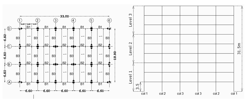 | Figure 1a. Typical floor plan of buildings & Figure 1b. Elevationof buildings |
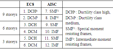
Further, as in all three buildings seismic forces are found dominant compared to wind forces, therefore seismic forces are considered for designing of the structures. For the typical floor plan twelve different cases are produced as shown in Table 1.Table 1. Various selected cases of the designed buildings
 |
| |
|
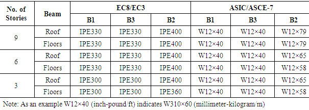
Following with the provisions of EC3, primary and secondary beams are designed; in order to satisfy both ultimate and serviceability limit states. All the beams are designed using steel grade S275. All the primary beams are also checked for the induced seismic actions together with reduced gravity actions according to EC8 prescriptions as illustrated in the companion part of the current paper. The secondary beams are IPE300.Accordingly for comparison the provisions of AISC/LRFD [10] together with ASCE-7 [9, 10] are referred for the combination of gravity loads and for the design of beams. In order to have the same effects on the buildings same gravity loading is used as defined by EC1. From the ASCE combination the secondary beams as designed are W12×40 which are simply supported along transversal axis. The beams designed for 9, 6 and 3 storeys buildings using EC3/EC8 and AISC/ASCE-7 provisions are shown in Table 2.Table 2. Primary beams for 9, 6 ans 3 storeys buildings
 |
| |
|
3. Structural Design
The buildings are designed assuming type C soil stratigraphic profile and 0.25 peak ground acceleration, the corresponding response spectrum is estimated for importance class II as per EC8. In order to have an equivalent response spectrum for AISC, soil type B with Ss and S1 as 1.08s and 0.7s respectively has been used as illustrated in the companion paper. The response spectrums obtained from the two codes are shown in Fig. 2.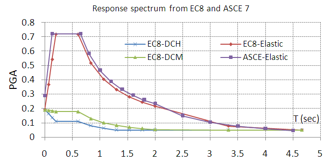 | Figure 2. Response spectrum from EC8 and ASCE |
Model response spectrum analysis is carried out with SAP 2000 advanced version14.0.0. In all the models rigid diaphragms are defined at each floor level to transfer the seismic forces in two orthogonal directions which practically could be achieved by the use of shear studs in the composite slab as shown in Fig.3.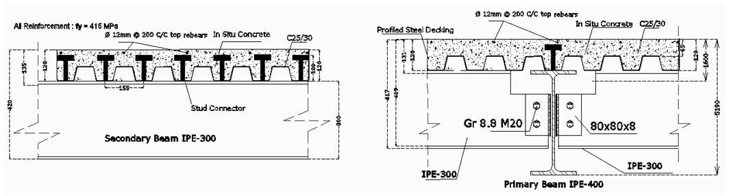 | Figure 3. Composite slab details |
4. Fundamental Period
Generally for estimating the response of a structure different approaches are available i.e. i). The equivalent static force analysis, ii). The response spectrum analysis and iii). The time history dynamic analysis and iv). Nonlinear Push-over analysis. For our purpose modal response spectrum analysis has been used as it is the most widespread method for the design of lateral load resisting structures. The fundamental periods of vibration as obtained from the codified formulation are almost 50% lower than the modal response spectrum analysis which is due to the fact that seismic codes tend to underestimate the fundamental periods of vibration to account for the stiffening effects of non-structural elements e.g. partition walls and infills. These effects are obviously of importance for steel frames which exhibits relatively low horizontal stiffness. The underestimation of the natural period leads to conservative design assumptions e.g. higher seismic base shear and in turn larger interstorey storey drifts. The first three fundamental periods for 9, 6, and 3 storeys buildings are shown in Fig. 4. Following code provisions, the fundamental period for 9, 6 and 3 storey frames are 1.13 sec, 0.83 sec and 0.49 sec, respectively.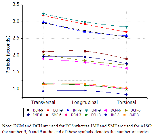 | Figure 4. First three fundamental periods of vibration for all 12 cases |
5. Overstrength Factor
The definition of overstrength factor in the two codes disagrees; for examples in American code (ASIC/ASCE), overstrength is a fixed for steel MRFs, instead in Eurocode 8 it is related to the strength of the beam and therefore it drastically increase when the stringent limit for damageability criteria is used in the design when dealing with brittle façade elements. If the beams are not influence by the drift limits, the overstrength factor is normally less than 3.0. The overstrength factor (Ω) as obtained from the designed beams using EC8 prescriptions for 9, 6 and 3 storeys buildings using DCH and DCM for transversal and longitudinal frames are shown in Fig. 5. The nomenclature of the frames is shown in the grid as shown in Fig. 1a.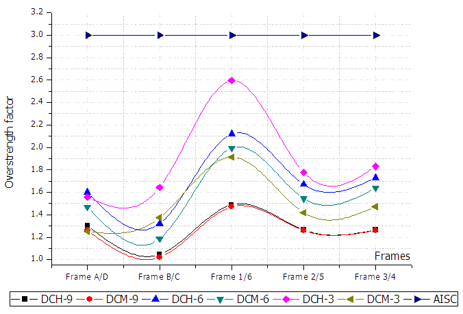 | Figure 5. Overstrength factors for 9, 6 and 3 storey MRF |
Since minimum value of Ω has to be used according to EC8, this gives an economical design as compared to AISC (as Ω is 3). In EC8 Ω strongly depends on the beams sizes as for same behavior factor with different beams dimension Ω changes and consequently as the beams size increases Ω increase and therefore for capacity design (and for weak beam strong column) column cross sections increases. AISC’s prescribed values of Ω are fixed for different structural systems and are independent of the beams sizes; therefore designer has to be careful while sizing the beams for strength so that weak beam strong column criteria may satisfy.
6. Capacity Design
In US codes [9, 10, 12-14] response modification factor (R) is normally employed in order to account for in elastic response of the framing system, These empirical factors (R, q) intended to account for damping, structural overstrength, and the inherent ductility of the structural system at enough displacements such as to overpass initial yielding of the system and thus arrive at the ultimate load displacement of the structural system. The concept of these factors (R, q) is proposed based on the postulate that well-detailed seismic framing systems could sustain large inelastic deformations without collapse (ductile behavior) and develop lateral strengths in excess of their design strength (often termed reserve strength). For DCH, response spectrum reduces slightly more than DCM and thus Ω increases slightly (as the primary beams are same). The profiles for the capacity design in the case of DCM requires almost the same strength as that of DCH as the fundamental period of the structure falls in the zone of the spectrum where different values of behavior factor q doesn’t have any significant change on the seismic forces as clear from Fig. 2. Therefore DCM is preferable for high periods (e.g. for 9 stories buildings) as the detailing of connections will not need high importance as compared to a DCH.Special care is required while deciding the ductility class for a structure where MRF has to be used as a lateral load resisting system as sometimes a high q factor may cause an uneconomical design due to detailing and the like, instead of sacrificing some kilograms of steel by increasing some of the column cross sections (in the case when a low ductility class is used in the design). The columns cross sections following EC8/EC3 and AISC/ASCE-7 prescriptions are shown for 9, 6 and 3 storeys MRFs in Table 3. Frame AA/DD are the exterior frames and frame BB/CC are the interior one as shown in fig. 1a. Heavy profiles are required for columns if S275 steel grade is used; therefore to avoid extra weight of the columns S355 steel grade is used.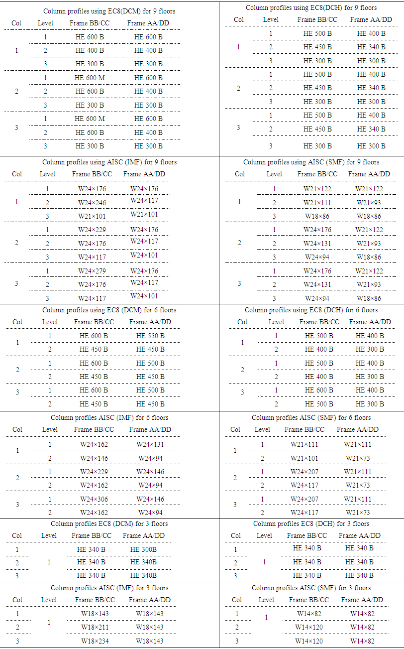 | Table 3. Columns profiles for 9, 6 and 3 storeys following EC8 and AISC prescriptions |
EC8 also provide an additional check for frame structures specifically to concrete structures, ΣMRc≥1.3 Σ MRb, that the sum of moment strength of columns at a particular node must be 30 percent greater than that of the sum of the moments of beams. The check is always satisfied when the beams are connected with the strong axis of the columns but rarely satisfied when beams are connected with the weak axis of the columns.
7. Drift Criteria
The interstorey drifts in both, longitudinal and transversal directions for EC8 using DCM and DCH are shown in Fig. 6. Limit b, is specified by EC8 for building having ductile nonstructural elements, therefore it is followed for satisfying the interstorey drift criteria.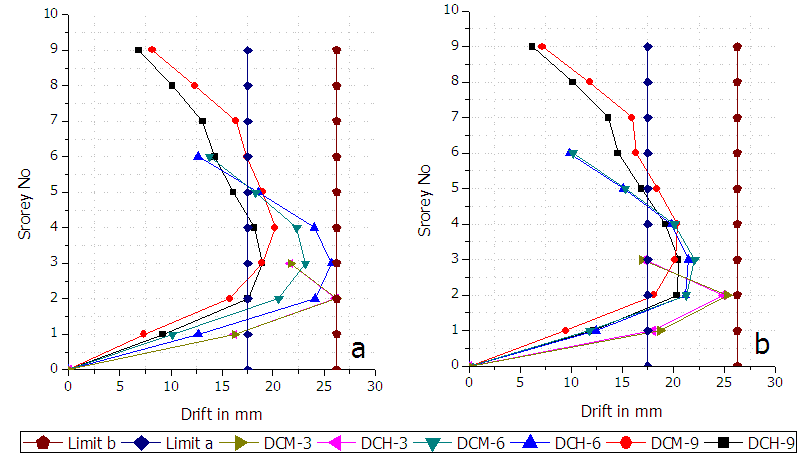 | Figure 6. Interstorey drifts for DCM and DCH using EC8 (a) Transversal (b) Longitudinal |
Using AISC provisions the drifts are easily satisfied and are shown in fig. 7.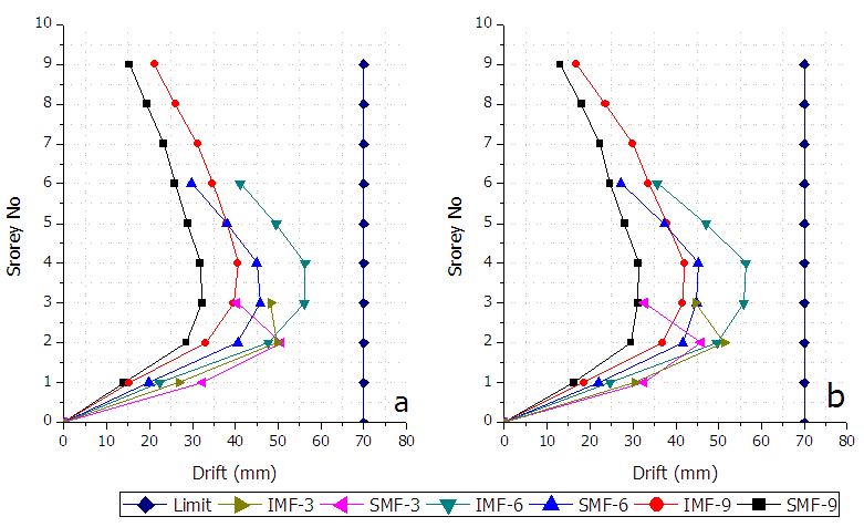 | Figure 7. Interstorey drifts for IMF and SMF using AISC (a) Transversal (b) Longitudinal |
8. Story Shear
The storey shear in longitudinal and transversal directions are plotted for 9, 6 and 3 storeys buildings in Fig. 8 Fig.9 and Fig. 10 respectively.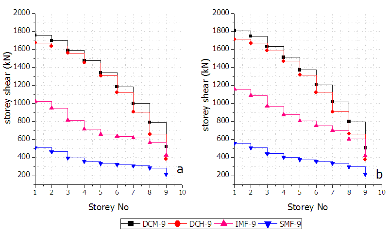 | Figure 8. Storey shears for 9 storeys (a) along transversal directions (b) along longitudinal directions |
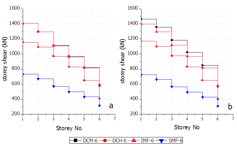 | Figure 9. Storey shears for 6 storeys (a) along transversal directions (b) along longitudinal directions |
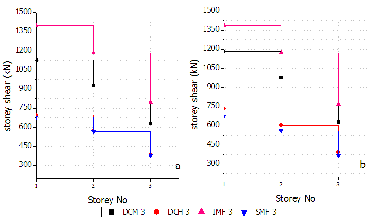 | Figure 10. Storey shears for 3 storeys (a) along transversal directions (b) along longitudinal directions |
Higher storey shears are obtained for 9 storeys buildings in EC8 and lower storey shears are obtained from AISC, which is due to the fact that EC8 gives a lower bound value for the inelastic spectrum but ASCE doesn’t mention any lower bound and suggests to use inelastic spectrum for modal analysis.
9. Weight Comparisons
A comparison of weights of column and beams for the two codes is shown in Fig. 11.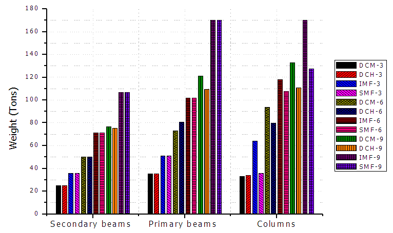 | Figure 11. Comparions of steel weights for columns and beams |
The weights of beams are high in the case of AISC as beams are designed for a load combination in which the live loads are increased by 70% and dead loads by 40% whereas in the case of EC8 the live loads are increased by 50% and dead load by 35%. The weights of the columns are dependent on Ω as cleared from the Fig. 11. Total weight and unit weight of the buildings for all 12 cases are shown in Fig. 12a and Fig. 12b respectively.The unit weights obtained from EC8 is in the range of 50 to 65kg/m2 whereas these are is in the range of 60 to 75kg/m2 in the case of AISC as clear from the Fig.12b.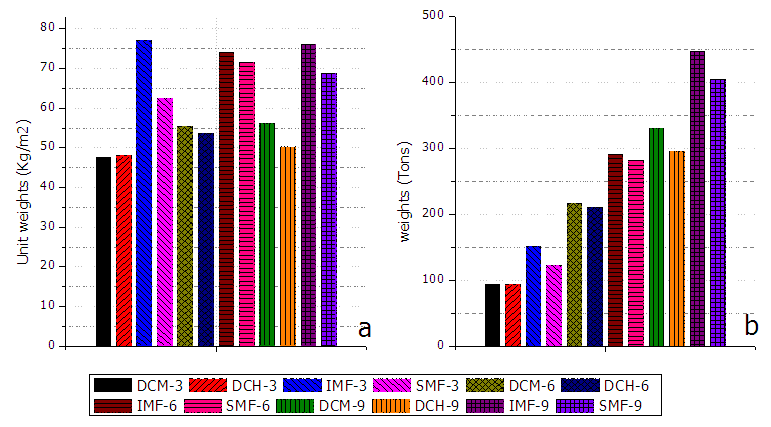 | Figure 12. Structural weights (a) Total weight of beams and columns (b) Structural unit weight |
10. Conclusions
A more detailed study (parametric study) for different structural system with different heights of structures and spans is required for a clear criticism on the two codes. It is observed from the present study that a strong difference exist in the definition of Ω between the two codes. The behavior factor, and thus the ductility concept in the two examined codes are quite similar. The reduction factors are different that needs to be investigate and analyze carefully while dealing with a structural system for design. The load combinations in the two codes are quite different from each other which affect the structural weight. From this study it is evident that for regular buildings of different heights as considered Eurocode gives more economical design both for medium and high ductility due to small Ω as compared to AISC for same conditions.
References
| [1] | M. T. Naqash, et al., "Seismic design of Steel Moment Resisting frames-European Versus American Practice," NED University Journal of Research, vol. Thematic Issue on Earthquake, pp. 45-59, October 2012 2012. |
| [2] | M. T. Naqash, "Optimum design of Steel Moment Resisting Frames using Eurocode 8," Doctorate PhD Thesis, Department of Engineering and Geology (Ph.D. Thesis), University of Chiete and Pescara, Pescara, 2012. |
| [3] | M. T. Naqash, et al., "European versus American practice for seismic design of steel Moment Resisting Frames (MRFs)," in XXIII Italian steel conference (CTA 2011), Lacco Ameno, Ischia, Naples, 2011, pp. 599-610. |
| [4] | M. T. Naqash, et al., "Critical overview on the seismic design of steel moment resisting frames " presented at the 45th IEP Convention 2012, Karachi, 2012. |
| [5] | EN-1998-1, "Eurocode 8, Design of Structures for Earthquake Resistance, Part 1: General rules, seismic actions and rules for buildings," in European Committee for Standardization, CEN, ed. 36 B-1050, Brussels, 2005. |
| [6] | EN-1993-1-1, "Eurocode 3. Design of steel structures, Part 1-1: General rules and rules for buildings," in European Committee for Standardization, CEN, ed. 36 B-1050, Brussels, 2005. |
| [7] | EN-1990, "Eurocode 0, Basis of structural design," in European Committee for Standardization, CEN, ed. 36 B-1050, Brussels, 2002. |
| [8] | EN-1991-1-1, "Eurocode 1, Actions on structures - Part 1-1: General actions - Densities, self-weight, imposed loads for buildings," in European Committee for Standardization, CEN, ed. 36 B-1050, Brussels, 2004. |
| [9] | ANSI/AISC-341-10, "Seismic provisions for structural steel buildings," ed. Chicago, Illinois 60601-1802: American Institute of Steel Construction, 2010. |
| [10] | ANSI/AISC-360-10, "Specification for structural steel buildings," ed. Chicago, Illinois 60601-1802: American Institute of Steel Construction, 2010. |
| [11] | R. O. Hamburger. (2009). Facts for Steel Buildings Number 3 - Earthquakes and Seismic Design. Available: http://www.aisc.org/store/p-1995-facts-for-steel-buildings-number-3-earthquakes-and-seismic.aspx. |
| [12] | UBC-1997, "International Conference of Building Officials," ed. Whittier, California 1997. |
| [13] | ASCE/SEI-7-10, "Minimum design loads for buildings and other structures," ed. 1801 Alexander Bell Drive Reston, Virginia 20191: American Society of Civil Engineers, 2010. |
| [14] | I. B. Code, "Internationa Building Code 2009 (IBC-2009)," ed. 4051 West Flossmoor Road, Country Club Hills, Illinois 60478. U.S.A: International code council, 2009. |

 Abstract
 Reference
 Full-Text PDF
 Full-text HTML