Muhammad Tayyab Naqash
Department of Civil Engineering, Islamic University in Madinah, KSA
Correspondence to: Muhammad Tayyab Naqash, Department of Civil Engineering, Islamic University in Madinah, KSA.
| Email: |  |
Copyright © 2017 Scientific & Academic Publishing. All Rights Reserved.
This work is licensed under the Creative Commons Attribution International License (CC BY).
http://creativecommons.org/licenses/by/4.0/

Abstract
With regard to the design of steel structures, the paper provides an overview on both Eurocode 8 provisions “Design of Structures for Earthquake Resistance” and AISC “Seismic Provisions for Structural Steel Buildings” documents. Design principles for several steel structural typologies are presented with more emphasis on the MRFs (Moment Resisting Frames). The concepts of performance based design, dissipative and non-dissipative structural elements are discussed in detail. In a companion paper the here treated codes are applied on real study cases of moment resisting framed buildings in order to provide useful cues for the technicians involved in the design of steel structures.
Keywords:
Seismic Resistant Steel Structures, Lateral Load, EC8, AISC, Moment Resisting Frames (MRFs)
Cite this paper: Muhammad Tayyab Naqash, Codal Comparisons for the Seismic Resistance of Steel Moment Resisting Frames (MRF). Part A: Codes Approach, International Journal of Construction Engineering and Management , Vol. 6 No. 6, 2017, pp. 254-263. doi: 10.5923/j.ijcem.20170606.04.
1. Introduction
Earthquake is a natural phenomenon representing a huge threat for any building which has not been properly designed and erected. Modern seismic design philosophy given by codes relies on the capability of structures to experience inelastic deformation without collapse. Steel is a strong, lightweight and tough material: capable to dissipate a huge amount of energy because of its high ductility which moreover can be fruitfully transformed by the application of capacity design rules; therefore it is an ideal material for designing seismic resistant steel structures. On this basis both the European code “EC8” [1] and American code “AISC” [2] provide rules for the design and construction of buildings and civil engineering works in seismic regions. Their purpose is to guarantee protection of human lives with controlled damages such as it remained operational for civic protection in the case of an earthquake. The current paper deals with the regulations provided by EC8 and AISC for the design of multi-storey steel structures, whereas a companion paper illustrates the design process of multi-storey residential buildings according to the same rules. Wide attention is devoted to both the performance levels required by codes and those provisions that technicians have to apply for their accomplishment. The main aim of this study is to provide an accurate description and a useful comparison of the two codes, in order to highlight the advantages and disadvantages of one over the other [3].
2. Performance Based Design Philosophy
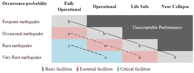
In the last decades, the most advanced codes and provisions have been based on the performance based design (PBD) approach. PBD is a useful tool for designing structure by taking into account different performance levels that must be accomplished for seismic demands having different return periods and depending on the importance of the designed structure, they must be related to earthquakes characterized by i) frequent, ii) occasional, iii) rare and iv) very rare occurrences as illustrated in Table 1. In general, these levels are characterized by a certain state of damage that is more severe, whereas the probability of occurrence of the event provoking them is low. The basic building performance levels provided by codes are i) fully operational, ii) immediate occupancy, iii) safety of life and iv) collapse prevention.Table 1. Performance Objective
 |
| |
|
In EC8 [1] two basic seismic design levels namely ‘no-collapse’ and ‘damage-limitation’ are considered. The first corresponds to a spread damaged state of the structure which nevertheless must retain a residual structural integrity and load bearing capacity, whereas the latter is related to a situation without the occurrence of significant damage and the associated limitations of use. For the ‘no collapse’ design level, seismic action should be based on a recommended probability of exceedance of 10% in 50 years (return period of 475 years) which corresponds to a rare earthquake, on the contrary ‘damage-limitation’ relates to a recommended probability of 10% in 10 years ( return period of 95 years).AISC [2] make use of the FEMA [4, 5] recommendations, where performance levels are defined as 1). Immediate Occupancy (IO) performance level 2). Life Safety (LS) performance level and 3). Collapse Prevention (CP) performance level. IO is referred to a post-earthquake state, where only minor structural damage has occurred and corresponds to a recommended probability of exceedance of 50% in 50 years, with 50% level of confidence that the structure will provide immediate occupancy. In LS probable structural damage is allowed with no collapse and with minimal falling hazards, here adequate emergency egress should be provided whereas CP is a post-earthquake state where complete or near complete collapse of the structure take place and corresponds to a recommended probability of exceedance of 2% in 50 years. An additional limit state is referred to as Operational limit state where yielding is not allowed.
3. Masses, Loads and Load Combinations
In EC8 it is specified that, the effects produced by the design seismic action shall be evaluated by taking into account the presence of the masses associated to all gravity loads appearing in the following combination of actions as shown in eq.(1).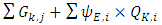 | (1) |
During an earthquake excitation, the loads that are firmly attached with the structural system contribute only to the seismic acceleration and so to the horizontal inertial forces, therefore for the part of the service load that is not attached to the structural system only a fraction is converted into the effective mass earthquake loading. Therefore, for the calculation of seismic mass, full permanent load in addition to variable load reduced by ψE,I, is taken. where ψE,i=φ× ψ2,i .The coefficients ψ2,i takes into account the reduced likelihood of loads Qk,i to be simultaneously present on the structure with its entire characteristic value during the design earthquake, it value ranges from 0 to 0.8. The coefficients φ account for a reduced participation of masses in the motion of the structure due to the non-rigid connection between them, and its vale ranges from 0 to 1.0. In eq.(1) Ed is the design action effect, Gk,j the permanent load and Qk,i the variable load.According to EC8 the design value Ed of the effects of actions in the seismic design situation shall be determined in accordance with EC0, which is expressed in eq.(2):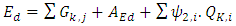 | (2) |
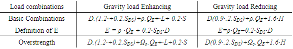
AEd represent the Earthquake load [4].On the other side, the combinations shown in Table 2 are used in ASCE [5] for evaluating the internal forces in the members due to the seismic induced forces. In which the earthquake load (E) is the combination of the horizontal seismic load and an approximation of the effects due to vertical accelerations that accompany the horizontal earthquake. As a consequence, it is split into two parts i.e. a horizontal effect and a vertical effect. In the combinations ρ denotes the redundancy factor, Ωo is the overstrength factor, SDS is spectral response acceleration parameter at 1 sec period. D is the dead load, S is the snow load, L is the live load [3, 6-8].Table 2. Seismic combination in ASCE
 |
| |
|
ASCE suggests that, redundancy factor (ρ) has to be assigned in both orthogonal direction. ρ is used to prevent progressive collapse of the structure. It is assigned as 1 for all eight classes mentioned in ASCE such as, (i) SDC B or C, (ii) drift calculations, (iii) non-structural components, (iv) non-building structures, (v) collector elements, splices and their connections where overstrength factor is used in the load combination, (vi) members and connections where overstrength factor is used in the load combination (vii) diaphragm loads and (viii) structural with damping systems. The redundancy factor is, 1.3 for SDC D, E and F, but again it is taken as 1.0 if SDC D, E and F satisfies the condition of regularity of plan along each level as illustrated in ASCE.
4. Seismic Demand and Representation of Seismic Action
4.1. Seismic Demand and Definition
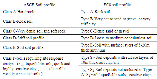
In EC8, the horizontal seismic action is basically described by two transversal and longitudinal orthogonal components. The vertical component, which is the third component, is described by a different elastic response spectrum. Further most importantly, EC8 defines two response spectra namely i). Type 1, which is used for the high seismic regions having surface wave magnitude (Ms) > 5.5 and ii). Type 2, for regions having moderate seismicity region with Ms < 5.5. Each spectrum is described by various soil types as shown in Table 3 [9].Table 3. ASCE and EC8 soil profile
 |
| |
|
In EC8, hazard is described in terms of single parameter age, which is the reference peak ground acceleration (PGA), on type A ground (rock soil). The agR is accounted for a reference return period (TNCR) of the seismic action for no-collapse requirements, which corresponds to a reference probability of exceedance given in 50 years (PNCR). The peak ground acceleration can be provided by the National Annex for the concern location. In the case of low seismicity, reduced or simplified procedures of structures may be used. The selection of categories of structures, ground types and seismic zones, for which the provisions of low seismicity apply for a country can also be found in the national annex.The performance differentiation is implemented by classifying structures into four different importance classes, having different γI (importance factor) and is used to amplify agR ranging from I (minor importance) to IV (prime importance). The recommended values of γI for classes I, II, III and IV are equal to 0.8, 1.0, 1.2 and 1.4, respectively.AISC seismic provisions suggests the use of ASCE [10] or IBC [11] for the evaluation of seismic loads and estimation of response spectrum. In the following ASCE is referred for the purpose, since ASCE does not use seismic zones like EC8 to establish design earthquake ground motion but rather it uses a parameter named Seismic Design Category (SDC), to determine a variety of aspects for building analysis and design such as, permissible analysis procedures, applicability of structural redundancy, load combinations, ductility requirements and methods for lateral load distribution. The concern site location Mapped Acceleration Parameters Ss (spectral response acceleration parameter at short period) and S1 (spectral response acceleration parameter at a period of 1sec) are determined from maps given in IBC [11] and ASCE [10] depending on the specified site for the probability of occurrence of 2% in 50 years (≈2,500 year return period). Since all the mapped accelerations are based on site class B (rocky soil), therefore site coefficients Fa and Fv are determined for Ss and S1. These coefficients account for site class. The corresponding MCE (Maximum considered earthquake) spectral response acceleration for short periods (SMS) and at 1sec period (SM1) are determined. The design earthquake spectral response acceleration parameter at short period SDS, and at 1sec period SD1 can be determined using eq.(3) and eq.(4).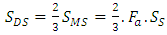 | (3) |
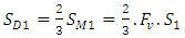 | (4) |
Four importance categories (I to IV) are defined also by the AISC code. For example Category I corresponds, buildings and other structures with a low hazard to human life in the event of failure, such as agricultural facilities whereas Category IV includes essential facilities. Importance factors for Category I, II, III and IV are 1.0, 1.0, 1.25 and 1.5 respectively. SDCs A, B and C as defined by AISC are generally applicable to buildings in areas of low to moderate seismicity and special seismic provisions are not mandatory. However special seismic provisions are mandatory in Seismic Design categories D and E which cover areas of high seismicity.
4.2. Representation of Seismic Action
Generally in both EC8 and AISC codes the horizontal components of the seismic actions are taken as acting simultaneously and therefore both the codes define to apply 100% seismic action in the considered direction with 30% seismic of the orthogonal direction. And in order to account for uncertainties in the location of masses and in the spatial variation of the seismic motion, both the codes suggests to assume that the calculated centre of mass at each floor i, is displaced from its nominal location in each direction by an accidental eccentricity: ei=±0.05Li, where ei is the accidental eccentricity of storey mass mi from its nominal location applied in the same direction at all floors; Li is the floor-dimension perpendicular to the direction of the seismic action.
5. Structural Behaviour
5.1. Inelastic Behaviour
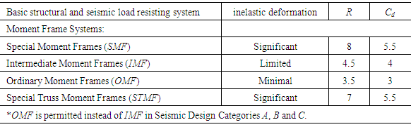
In EC8 the concept of energy dissipation capacity of steel structures is prescribed by means of three ductility classes, namely. i) DCL (Ductility Class Low), where steel structures are designed and dimensioned according to EC3 [12] with some criteria, in order to have minimum ductility, ii) DCM (Ductility Class Medium), where structures are designed, dimensioned and detailed according to code specified spectrum, allowing the structure to work in the inelastic domain under cyclic actions without brittle failures, and iii) DCH (Ductility Class High), which corresponds to structures that are designed, dimensioned and detailed so that the structural response to seismic action is according to the considered failure mechanism with a large amount of energy dissipation by designing some structural members to dissipate the earthquake induced energy. The seismic design loads specified in AISC code have been developed considering the energy dissipation which generates during inelastic response of the system. AISC does not mention low, medium or high ductility but instead it mentions special, intermediate and ordinary structural system. In AISC, Special moment resisting frames (SMF), Intermediate moment resisting frames (IMF) and Ordinary moment frame (OMF) are designed and detailed such that it should undergo significant, limited and minimal inelastic deformation respectively, when subjected to a desired seismic excitation. The Ordinary moment frame (OMF) is intended to provide for limited levels of inelastic rotation capability that are less than those of the IMF. Special truss moment frames (STMF) are expected to withstand significant inelastic deformation within a specially designed segment of the truss when subjected to the forces from the motions of the design earthquake.
5.2. Material Overstrength
EC8 suggests that the distribution of material properties in the structure shall be such that, dissipative zones form where they are intended to in the design. Conventionally for the resistance of a steel member yield strength (fy) is used which is lower than the actual expected strength, therefore codes amplify the nominal yield strength by a factor to account for the actual expected strength of steel and to use in the capacity design to achieve a ductile behaviour. Therefore in EC8 the maximum yield strength fy,max of the steel should satisfies the following expression fy,max ≤ 1.1γovfy, where γov is the overstrength which is the ratio of actual to design yield strength of steel and fy is the nominal yield strength. The amplification of fy with 1.1 account for other material effects like isometric strain hardening. As the steel grade increases, the value of γov decreases. The recommended value of γov is 1.25. The values of γov for different steel grades are also provided in National Annexes. AISC suggests that the structural steel use in the seismic load resisting systems shall fulfil the specifications as provided by ASTM (American Society for Testing and Materials). The specified minimum yield strength of steel to be used for members in whom inelastic behaviour is expected shall not exceed 345 MPa unless the suitability of the material is determined by testing or other rational criteria. To obtain the expected actual yield strength of steel from the nominal yield strength a similar approach like EC8 is adopted in AISC where fy is amplified by a factor Ry which accounts for the profile shape and for the grade of steel used, its value ranges from 1.1 to 1.5.
5.3. Behaviour and Response Modification Factor
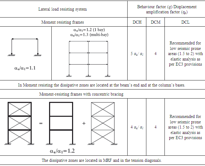
Whether nonlinear dynamic analysis of a structure requires a lot of computational efforts, on the other hand the elastic analysis causes huge cost to the structure. Therefore codes suggests the use of reduce spectrum for the estimation of lateral forces except for very important structures and for the complex structures that require to do not undergo damage under strong event of earthquakes. The response modification factor is the ratio of the “elastic strength demand” to the “design strength demand” or simply it is the ratio of the elastically induced forces to the prescribed design forces at the ultimate state under the specified ground motion during an earthquake. The response modification or behaviour factor is used to reduce the ultimate seismic event, and the amount of reduction depends on the overstrength and ductility of the structure. EC8 make use of behaviour factor q as response modification factor and displacement amplification factor qd for MRF as illustrated in Table 4 below. In the case if the building is irregular along elevation then only 80 percent of q should be used as prescribed by EC8. Table 4. Behaviour factor for MRF and Dual system in EC8
 |
| |
|
The horizontal seismic actions are multiplied with α1 and αu , the multiplication of α1 represents the arrival of first flexural resistance in a member and the multiplication of αu represents the formation of plastic hinges in some members that are sufficient for the global instability of the structure. The multiplier αu/α1 with q factor demonstrates the redundancy factor and this ratio represent “the structure capable lateral force” to “the lateral force when the first element of the structure reaches its resistant capacity”. This ratio can be obtained from pushover analysis and should not exceed 1.6. The energy dissipation capacity for the different frames in AISC is taken into account by the use of Response modification factor (R) which depends on the type of frame used for the lateral load resisting system and accounts for (i) Ductility, (ii) Overstrength, (iii) Redundancy, (iv) Damping, (v) Past behaviour. Since the reduced spectrum has to be used for the verification of interstorey drifts therefore specific seismic amplification factors Cd is multiplied with the estimated loads for strength. The values of Cd are generally lower than the R values as shown in Table 5.Table 5. Design factor for structural steel systems
 |
| |
|
AISC also limit the height of IMF for seismic design categories for example, there is no height limitation for IMF in SDC B and C whereas in SDC D the height is limited to 10.7m and it is restricted to not be used in SDC’s E and F. There is no height limitation for the use of OMF in SDC’s B and C whereas it is restricted to be used in SDC’s D, E and F. The rotational capability of the above mentioned frames is illustrated in section 6.4 of the current paper.
5.4. Cross Section Limitations
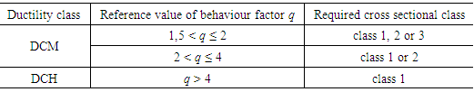
The cross-sectional shapes of rolled steel sections are designed such that, to provide efficient performance for specific uses. Cross-sections are classified as "plastic", "compact", "semi-compact" or "slender" according to the proportions of the cross-section. Semi compact and slender cross-sections are actually not prohibited but the calculated load carrying capacity is reduced because of local buckling whereas compact sections are capable of developing full plastic moment capacity, Mp, and sustaining large hinge rotation before the onset of local buckling. Since the formation of local buckling in a cross section reduce the capability of energy dissipation to high extent, therefore to avoid local buckling EC8 restricts the use of class of cross section for a given ductility class as shown in Table 6. Fig. 1 shows M-φ curve for cross section classifications.Table 6. Cross section limitation for behaviour factor
 |
| |
|
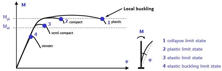 | Figure 1. Moment vs rotation (M-φ) curve for steel cross sections |
In fact class 1 sections are unaffected by local buckling and are able to develop and maintain their fully plastic resistances until a collapse mechanism forms.To provide, reliable inelastic deformations in seismic load resisting systems that require high levels of inelasticity, AISC suggests the use of compact sections for seismic design. For compact members b/t ≤ λp whereas for non-compact members λp ≤ b/t ≤ λr. AISC suggests that the width-thickness (b/t) ratios of compression elements of the SLRS should not exceed the limiting slenderness ratios, which for compact sections and for seismically compact sections is given by λp and λps respectively. Where λp denotes the slenderness of compact section and λps denotes limited slenderness of seismically compact sections and λr denotes slenderness of non-compact sections. For seismically compact members AISC limit, λp to λps. AISC gives formulation for the computation of λps for both stiffened and unstiffened elements. The limiting values for compact section (for seismic and non-seismic regions) in AISC specification for flanges and webs are defined as:For flanges: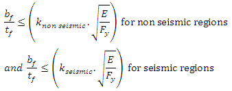 Where bf is the width of flange, tf the thickness of flange and Fy the yield stress. The factor knon seismic and kseismic depends on the type of elements and the type of subjected forces on the element. Generally knon seismic > kseismicFor webs: Ÿ For non-seismic regions
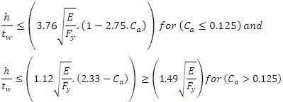 Ÿ For seismic regions
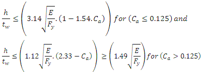 Where Ca=Pu/(∅b.Py), Pu is the required compressive strength, Py is the axial yeild strength and φb is 0.9, h is the clear distance between flanges, tw is the thickness of web and Fy is the yield stress.
6. Capacity Design Rules
6.1. Capacity Design Checks
EC8 recommends the capacity design approach for the design of members to have a global ductile behaviour of structure. In case of MRF, the weak beam and strong column concept should be followed. For the beams of MRF with classes 1 and 2 cross sections, the inequalities, in eq.(5a), eq.(5b) and eq.(5c) should be verified at the location where the formation of hinges is expected : | (5a) |
 | (5b) |
 | (5c) |
The columns shall be verified in compression considering the most unfavourable combination of the axial force and bending moments.In the checks, NEd, MEd, VEd should be computed using eq.(6), eq.(7) and eq.(8) respectively: | (6) |
 | (7) |
 | (8) |
The column shear force VEd resulting from the structural analysis should satisfy the following expression: VEd / Vpl,Rd ≤ 0.5. Being VEd =VEd,G +VEd,M ; NEd is the design axial force; (gravity +seismic),MEd is the design bending moment; VEd is the design shear; (gravity +seismic),Npl, Rd , Mpl, Rd , Vpl, Rd are design resistances in accordance with EC3,VEd,G is the design value of the shear force due to the non-seismic actions (gravity only),VEd,M is the design value of the shear force due to the application of the plastic moments Mpl,Rd,A and Mpl,Rd,B with opposite signs at the end sections A and B of the beam. AISC suggests the use of load combinations for the design of members for the corresponding applicable building code used for the load definition, for ASCE to be an applicable building code the load combination as defined in section 3 of the current paper should be used. AISC “Seismic provisions” provides strength checks for members which should be fulfilled with the load combinations where overstrength factor is used for the capacity design criteria.
6.2. Structural Overstrength
Overstrength factor (reserve strength) is the ratio of “apparent strength” to the “design member strength”. The Ω factor is required to achieve the capacity design approach where a hierarchy is defined such that the ductile elements yield before other primary elements. In order to have a ductile behaviour of structure both ASCE and EC8 suggest the use of capacity design criteria (illustrated in section 6 of the current paper) which accounts in amplifying the seismic forces of some element by system overstrength factor (Ω). The overstrength factor has strong influence on the dimensions of member size and thus on the economy of the structure itself. A high value of Ω could cause oversizing of the members whereas smaller value of Ω could cause unexpected failure mechanisms. In EC8, Ω can be calculated as shown below.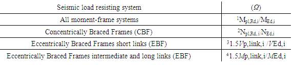 Ÿ 1MEd,i is the design value of the bending moment in beam i in the seismic design situation and Mpl,Rd,i.is the corresponding plastic moment.Ÿ 2 Npl,Rd,i is the design resistance of diagonal i; NEd,i is the design value of the axial force in the same diagonal i in the seismic design situation.Ÿ 3VEd,i, MEd,i are the design values of the shear force and of the bending moment in link i in the seismic design situation.Ÿ 4Vp,link,i, Mp,link,i are the shear and bending plastic design resistances of link i. For any of the seismic load resisting system minimum value of Ω should be utilized in the calculation. Since, in EC8 minimum value of Ω has to be used in the capacity design, therefore the overall structural behaviour corresponds to the development of first plastic hinge in the beams and thus due to the redistribution of forces, columns will be subjected to higher forces and this could cause the formation of plastic hinges. On the contrary, maximum Ω will provide anticipated failures of beams than columns, but also will oversize the dimensions of the members and will lead to an uneconomical design. A modified value of Ω as shown in eq.(9) is suggested [13],
 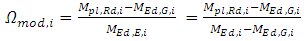 | (9) |
In modified Ω, bending moment due to reduced gravity forces are subtracted from both Mpl,Rd,i and MEd,i , which cause an increase in the code specified Ω. The value of Ω needs a more detailed study in order to assure a global ductile mechanism of the structure and not only on the first formation of plastic hinges in the beam. According to AISC the following overstrength values should be used,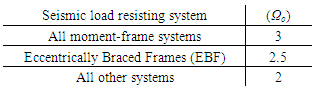
6.3. Strong Column Weak Beam Concept
For global ductility columns must be stronger than beams therefore EC8 suggests that the condition in eq.(10) must be satisfied at all seismic beam to column joints: 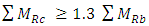 | (10) |
Where ΣMRc and MRb is the sum of the design values of the moments of resistance framing the joint of the columns and beams respectively. The factor 1.3 takes into account the strain hardening and the material overstrength could be the multiplication of 1.1 γov and as a general rule is taken as 1.3.In AISC eq.(11) need to be satisfied in the case of SMF at the column beam connections,  | (11) |
Where ΣM*pc is the sum of the moments in the column above and below the joint at the intersection of the beam and column centrelines and is calculated from eq.(12). 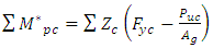 | (12) |
ΣM*pb is the sum of the moments in the beams at the intersection of the beam and column centrelines.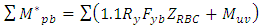 | (13) |
Zc and ZRBS is the plastic section modulus of column and minimum plastic modulus at reduced beam section respectively,Fyb and Fyc are the specified minimum yield stress of beam and column respectively, Ry is the ratio of expected yield stress to specified minimum yield stress,Puc is the required compressive strength using LRFD load combinations,Muv is the additional moment due to shear amplification.It is evident from eq.(10), where plastic moment of beam is amplified by a factor 1.1Ry which resembles eq.(10) as suggested by EC8. The value of Ry ranges from 1.1 to 1.5.
6.4. MRF Beam to Column Joints
The beams to column joints of MRFs are generally full strength and rigid in order to resist the seismic forces and are therefore required to possess high strength with respect to the connected members such that the formation of the plastic hinge form in the beam rather than in the connection itself. The basic design criterion is based on the assumption that the joint should not be the dissipative component of a ductile frame. Local failure occurs in the steel frame when the rotation capacity of a beam exceeds a limit that cause local buckling of the cross section. For the use of beams end to be the dissipative zones beam-to-column connections should be designed for the required degree of overstrength taking into account the moment of resistance and the shear force of the connected beam.EC8 allows to use dissipative semi-rigid and/or partial strength connections, if all of the following requirements are verified: a) the connections have a rotation capacity consistent with the global deformations; b) members framing into the connections are demonstrated to be stable at the ultimate limit state (ULS); c) the effect of connection deformation on global drift is taken into account using nonlinear static (pushover) global analysis or non-linear time history analysis.The connection design should be such that the rotation capacity of the plastic hinge region θp is not less than 35mrad for structures of DCH and 25mrad for structures of DCM with q > 2. The rotation θp is defined as θp = δ / 0.5L and is shown in Fig. 2. Where δ is the beam deflection at midspan; L is the beam span.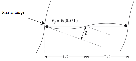 | Figure 2. Rotation capacity of connection |
In AISC the prescribed three frame types SMF, IMF and OMF offer three different levels of expected seismic inelastic rotation capability. SMF and IMF are designed to accommodate approximately 0.03 and 0.01 radian, respectively. OMFs are designed to remain essentially elastic and are assumed to have only very small inelastic demands. It is assumed that the elastic drift of typical MRFs is usually in the range of 0.01 radian and that the inelastic rotation of the beams is approximately equal to the inelastic drift. SMF, IMF and OMF are assumed to accommodate total interstorey drifts in the range of 0.04, 0.02 and 0.01 radian, respectively.
7. Deformation Requirements
In both EC8 and in AISC, two deformation criteria needs to be satisfied i.e. second order effects and interstorey drifts.
7.1. Criteria for P-Delta Effects
Structures are generally divided into sway and non-sway frames, the conditions assumed by codes for dividing non-sway structures by the sway ones is often given in terms of θ, by which the design loading would have to be increased to cause elastic instability in a global mode.In EC8 it is given by eq.(14). | (14) |
θ is the interstorey drift,Ptot is the total gravity load at, and the above storey in seismic design situation VEd is the total seismic storey shear,h is the interstorey height.dr is the design interstorey driftIf 0.1< θ ≤0.2, then all the computed seismic forces and displacements should be multiplied by a factor θ = 1/(1- θ) in order to take into account P-Delta effects, θ may not exceed 0.3 as well.In ASCE the P-delta effects on story shears and moments, member forces and moments, and the story drifts induced by these effects are not required to be considered if θ ≤ 0.1.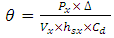 | (15) |
where Px = total vertical load at and above level x (no load factor need exceed 1.0), Δ = design story drift resulting from VX, Vx = seismic shear acting between levels x and x-1, hsx = the story height below level x. If θ > 0.1 then | (16) |
where β is the ratio of the shear demand to the shear capacity of the story in question (effectively the inverse of the story overstrength). β may conservatively be taken as 1.0. Further the analysis of the structure should explicitly consider the geometric nonlinearity introduced by P-Δ effects.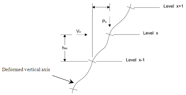 | Figure 3. Deformed vertical axis of structure due to seismic forces |
7.2. Inter Story Drift Criteria
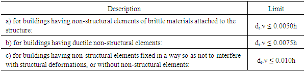
EC8 [2] prescribes the followings limitations for drift criteria as shown in Table 7 below, Table 7. EC8 drift limitations
 |
| |
|
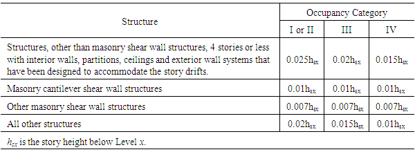
Where dr is the design interstorey drift, h is the storey height; ν is the reduction factor which takes into account the lower return period of the seismic action associated with the damage limitation requirement. Different values of ν may be defined for the various seismic zones of a country, depending on the seismic hazard conditions and on the protection of property objective. The recommended values of ν are 0.4 for importance classes III and IV and ν = 0.5 for importance classes I and II.In ASCE the amplified story drift is determined by multiplying the elastic drift caused by the horizontal component of the earthquake load E by a deflection amplification factor Cd, which is dependent upon the type of building system used. Table 8 explain the limitations of ASCE code for interstorey drift.Table 8. ASCE drift limitations
 |
| |
|
8. Conclusions
Starting from the load definition different load combinations are provided by the two codes which could cause a different response of the structure. ASCE does not use seismic zones to establish design earthquake ground motion instead EC8 use reference peak ground acceleration to define the spectrum. Also two different spectra are defined by EC8 for low and high seismic regions whereas ASCE defines a single spectrum. EC8 takes into account the ductility classes to define the behaviour factor whereas AISC defines response modification factor for Special, Intermediate and Ordinary moment resisting frames. The Overstrength factors in EC8 depend on the strength of beams and on the seismic actions whereas in AISC values for these factors are fixed values without the use of any formulation. Further drift criteria in both the codes are different from each other, in EC8 the drifts could be obtained from the design spectrum by multiplying with an amplification factor of qd (q) whereas in AISC an amplification factor Cd should be used which is different than R. The concept of the use of expected actual yield strength in the capacity design resembles each other. In general both codes define the ductility class as i). Use of the class of cross section, which in EC8 is class 1 and 2 and in AISC is restricted to the use of limited slenderness parameter for compact element and ii). Different rotation capacity of the plastic hinge region. A Similar approach of strong column weak beam could be found in the two codes.
References
| [1] | EN-1998-1, "Eurocode 8, Design of Structures for Earthquake Resistance, Part 1: General rules, seismic actions and rules for buildings," in European Committee for Standardization, CEN, ed. 36 B-1050, Brussels, 2005. |
| [2] | ANSI/AISC-341-10, "Seismic provisions for structural steel buildings," ed. Chicago, Illinois 60601-1802: American Institute of Steel Construction, 2010. |
| [3] | M. T. Naqash, "Optimum design of Steel Moment Resisting Frames using Eurocode 8," Doctorate PhD Thesis, Department of Engineering and Geology (Ph.D. Thesis), University of Chiete and Pescara, Pescara, 2012. |
| [4] | P. FEMA-350, "Recommended seismic design criteria for new steel moment-frame buildings FEMA-350," in FEMA-350, Rich mond, Calif, ed. Washington, DC, 2000. |
| [5] | FEMA-356, "Commentary for the seismic rehabilitation of buildings, FEMA-356," in Federal Emergency Management Agency, ed. Washington, DC, 2000. |
| [6] | M. T. Naqash, et al., "European versus American practice for seismic design of steel Moment Resisting Frames (MRFs)," in XXIII Italian steel conference (CTA 2011), Lacco Ameno, Ischia, Naples, 2011, pp. 599-610. |
| [7] | M. T. Naqash, et al., "Effects of capacity design rules on seismic performance of steel moment resisting frames," presented at the 15 World Conference on Earthquake Engineering (WCEE), Lisbon Portugal, 2012. |
| [8] | M. T. Naqash, et al., "Seismic design of steel moment resisting frames-European versus American practice," NED University Journal of Research, vol. 9, pp. 45-60, 2012. |
| [9] | A. Elghazouli, "Assessment of capacity design approaches for steel framed structures," Journal of Steel Structures, vol. 5, pp. 465-475, 2005. |
| [10] | ASCE/SEI-7-10, "Minimum design loads for buildings and other structures," ed. 1801 Alexander Bell Drive Reston, Virginia 20191: American Society of Civil Engineers, 2010. |
| [11] | I. B. Code, "Internationa Building Code 2009 (IBC-2009)," ed. 4051 West Flossmoor Road, Country Club Hills, Illinois 60478. U.S.A: International code council, 2009. |
| [12] | EN-1993-1-1, "Eurocode 3. Design of steel structures, Part 1-1: General rules and rules for buildings," in European Committee for Standardization, CEN, ed. 36 B-1050, Brussels, 2005. |
| [13] | A. Elghazouli, "Assessment of European seismic design procedures for steel framed structures," Bulletin of Earthquake Engineering, vol. 8, pp. 65-89, 2010. |

 Abstract
 Reference
 Full-Text PDF
 Full-text HTML