-
Paper Information
- Next Paper
- Previous Paper
- Paper Submission
-
Journal Information
- About This Journal
- Editorial Board
- Current Issue
- Archive
- Author Guidelines
- Contact Us
International Journal of Construction Engineering and Management
p-ISSN: 2326-1080 e-ISSN: 2326-1102
2017; 6(6): 240-253
doi:10.5923/j.ijcem.20170606.03

Cyclic Behavior of Footings on Dry Sand under Different Rates of Loading
 Abstract
 Reference
 Full-Text PDF
 Full-text HTML
Mohammed Y. Fattah, Hussein H. Karim, Hiba H. Al-Qazzaz
Building and Construction Engineering Department, University of Technology, Baghdad, Iraq
Correspondence to: Mohammed Y. Fattah, Building and Construction Engineering Department, University of Technology, Baghdad, Iraq.
| Email: |  |
Copyright © 2017 Scientific & Academic Publishing. All Rights Reserved.
This work is licensed under the Creative Commons Attribution International License (CC BY).
http://creativecommons.org/licenses/by/4.0/

Research on the cyclic vertical loading problem for sand is particularly scarce, and most has been in commercial confidence. This research is conducted to study the experimental behavior of dry sandy soil under foundations subjected to vertical cyclic compression load. A total of sixty three models have been tested to study the behavior of shallow footings under cyclic load of different rates. A new compression machine was manufactured to apply both monotonic and cyclic loading. Three relative densities of sand, two footing shapes, three depths of foundation embedment and three rates of loading were tried. It was concluded that the more the depth of footing (Df increasing), the soil settlement decreases. In general, when other factors are remaining constant, the bearing capacity of the soil goes on increasing when the depth or width of the foundation increases. The total settlement of a footing continues to increase during the time of the load and reaches a maximum value at the end of dwell time. During the decay period of the load, the footing rebounds to some degree. The effect of loading rate depends on the density of sand bed. In loose sand, the cyclic load settlement increases with the rate of loading, while in dense sand, the cyclic load settlement decreases with rate of loading.
Keywords: Dry sand, Cyclic load, Rate of loading, Settlement
Cite this paper: Mohammed Y. Fattah, Hussein H. Karim, Hiba H. Al-Qazzaz, Cyclic Behavior of Footings on Dry Sand under Different Rates of Loading, International Journal of Construction Engineering and Management , Vol. 6 No. 6, 2017, pp. 240-253. doi: 10.5923/j.ijcem.20170606.03.
Article Outline
1. Introduction
- Numerous researches have been directed towards assessment of the behavior of cohesionless soils under cyclic loading conditions. The researchers showed that the response of soil to cyclic loading is more critical than to monotonic loading.The safe operation of installations such as offshore structures, wind turbines, pylons or silos relies on their foundations ability to sustain cyclic loading. Model tests by Chan and Hanna (1980) showed that displacement piles cyclic response in sand is affected by: the number (N) and frequency (f) of cycles; the mean shaft load and shaft cyclic amplitude Qmean and Qcyclic, loading history and sand characteristics. Sand responses to monotonic and cyclic shearing depend on their fabric, initial state (void ratio and stresses) and degree of shearing. Ishihara at el., (1975). Kuwano (1999) and Kuwano and Jardine (2007) reported multiple triaxial probing and load-unload experiments that involved imposing radial effective stress paths on two fine silica sands and also glass balloting. Employing highly instrumented and automatically controlled triaxial equipment, they examined a wide range of effective stress conditions, over-consolidation ratios and initial void ratios.A cyclic loading may be caused by traffic (high speed trains, magnetic levitation trains), industrial sources (crane rails, machine foundation), wind and waves (on – shore and off – shore wind power plants, coastal structures) or repeated filling and emptying processes (Watergates, tanks and silos). Furthermore, construction processes (e.g. vibro installation of sheet piles) and mechanical compaction (e.g. vibratory compaction) impose cyclic loads into the soil. A cyclic load of the soil may be also caused by endogenous sources. Earthquake events due to a slip between adjacent tectonic plants lead to a propagation of shear waves. The shear waves induce a cyclic shearing of the soil. Cyclic loading of the soil can lead to an accumulation of permanent deformations or to a possible liquefaction due to a build-up of excess pore water pressure.
1.1. Cyclic Loading on Cohesionless Soils
- Carter etal. (1980) observed that for stress-controlled loading, failure will eventually occur if the soil sample is subjected to a sufficient number of load repetitions. The cyclic deviator stress increased, and more damage occurs in the case of two-way stress-controlled cycling (i.e. in the case of reversal stresses) than in one-way cycling. Marr and Christian (1981) carried out drained cyclic triaxial tests on alluvial sand. The study suggested that the permanent strain in soil was not only a function of cyclic shear stress, but also depended on ratio of mean shear stress to mean normal stress and on initial porosity of the soil. Airey et al. (1992) conducted cyclic load tests on carbonate sand (with relative density R.D. = 90%). It was observed that in the first cycle, the soil expands but in all the subsequent cycle there was a net contraction. The rate of contraction decreased as the number of cycle increases.Fattah (2005) applied the kinematic double hardening model ALTERNAT to simulate the cyclic behavior of sand. The model can describe several phenomena of sand behavior such as the stress dilatancy, hardening, densification and cyclic mobility. The effect of initial stress anisotropy through the values of the coefficient of lateral stress at rest (Ko) was studied. It was concluded that the maximum shear strain increases with the increase of the coefficient of lateral stress at rest. On other hand, the maximum spherical (volumetric) strain decreases with the increase of the coefficient of lateral stress at rest until a value of about (Ko=0.72) is reached, above this value, the maximum spherical strain increase. This behavior reflects the stress dilatancy that takes place in dense sand where the values of Ko are high. The stress dilatancy increases as the value of Ko increases at the start of loading. As the number of increments increases, the effect of Ko decreases. This can be attributed to the densification that might take place under cyclic loading till the sand reaches a stable condition.Sudhakar and Sandeep (2016) presented an experimental study to investigate the cyclic as well as static behavior of model ring footing and circular footing resting on reinforced sandy soil. Coir geocell was used as soil reinforcement. The study showed that, with the provision of geocell reinforced sand cushion, there is substantial reduction in settlement of both ring and circular footings due to modified stress distribution. The beneficial effect in terms of increased bearing capacity and reduced settlement was related to the width and depth of placing geocell mattress.The objective of the present study is to investigate the effect of loading rate and depth of embedment on the cyclic behavior of shallow footings.
2. Experimental Work
2.1. Index Properties of Soil
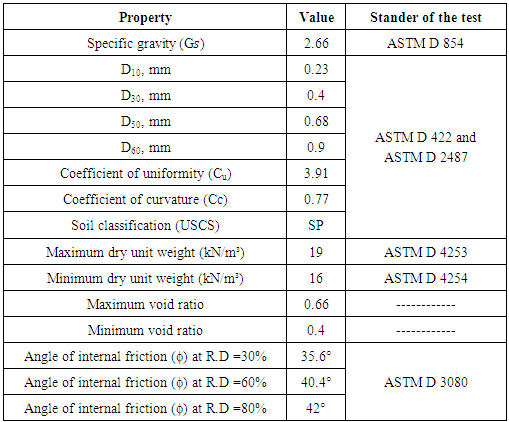
- Air dried sand brought from the holy city of Karbala was used in the present study. The properties of this sand including specific gravity, grain size distribution, and minimum and maximum dry unit weights were measured. A summary of the test results with standard specification that are followed in each test is presented in Table 1. According to the grain size distribution results, it can be seen that the sand is of medium to coarse-grained in size. This sand is classified as poorly graded sand (SP) according to the Unified Soil Classification System (USCS).
|
2.2. Load Setup Design and Manufacturing
- To study the effect of different parameters in transferring the cyclic load due to traffic motion in sandy soil, it is necessary to simulate the conditions as close as possible to those occurring in the field. To achieve this goal, a special testing apparatus and other accessories were designed and manufactured. The manufactured loading machine has the capability of applying different cyclic loads begin from 134.5 N to 422.73 N when using (cylinder 1) and begin from 328 N to 1031 N when using (cylinder 2). The general view of the manufactured apparatus is illustrated in Figure 1. The manufactured loading machine consists of the following parts:1. Loading steel frame,2. Axial loading system,3. Model footing, 4. Steel container (testing box), and5. Cone and shank
2.3. Loading Steel Frame
- To support and ensure the verticality of the pneumatic jack that used in applying the vertical load on footing, a steel frame was designed and constructed for this purpose as shown in Figure 1.
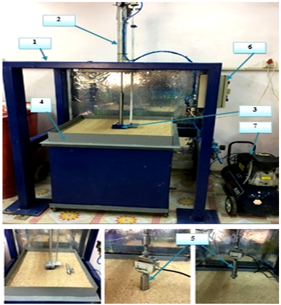 | Figure 1. General view of the manufactured apparatus: 1-Loading steel frame, 2- Axial loading system, 3- Model footing, 4- Steel container, 5- Cone and shank, 6- Control system, and 7- Air compressor system |
 65 mm) and wall thickness of 4 mm. The dimensions of the steel frame (length
 width
width height) are respectively (1150 mm
 810 mm
 1520 mm). To strengthen the steel frame to with stand the applied load, two beams were added to support the load frame, part No. 4 as shown in Figure 2.
 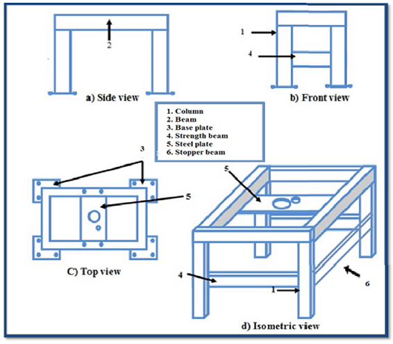 | Figure 2. Schematic diagram of the loading frame |
 300 mm) was connected to a transverse beam by four bolts (of diameter 20 mm) in the center of the frame in order to carry the pneumatic jack system as shown in Figure 3. The steel frame was fixed to the floor base using four base plates of dimensions (250 mm
 250 mm
 10 mm). Each base plate was fixed to the floor using four anchor bolts 12 mm in diameter.
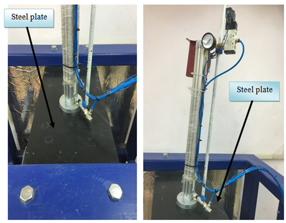 | Figure 3. Steel plate to support the jack |
2.4. Axial Loading System
- The axial load system consists of:
2.4.1. Pneumatic Cylinder System
- The system is made up of two pneumatic cylinders; the first is used to apply a force between 134.5 to 422.73 N, which is called a low range load cylinder (cylinder 1). The second cylinder is used for applying medium and high load (cylinder 2) which is called medium and high range load cylinder. The piston is made of aluminum and contains pressure washer- packing made of the viton. The two cylinders are connected with pneumatic valves by flexible hose. The maximum operating pressure for the two cylinders is 10 bars (100 kPa). Each cylinder contains a piston with inner diameter equal to the inner diameter of each cylinder. The inner diameter of the first cylinder (cylinder 1) is 32 mm. The inner diameter of the second cylinder (cylinder 2) is 50 mm. This piston moves with a stroke of 500 mm up and down and this movement is similar in both cylinders. On the other hand, this piston is connected to a movable shaft with a diameter of 10 mm in the first cylinder and a diameter of 20 mm in the second cylinder. The end of the movable shaft is connected to the upper footing (attached to the device) and the end of the shaft is threaded. These threads are with the same dimensions in the two cylinders as the same upper footing of the device is used.Another shaft is used with the two cylinders, which is installed on the other side of the top of the device (upper pressure plate or the upper movable plate) with 14 mm diameter. It is used to prevent the rotation of the footing (the square or circular footing used in testing) and is moving up and down with the cylinder piston movement, as shown in Figure 4.
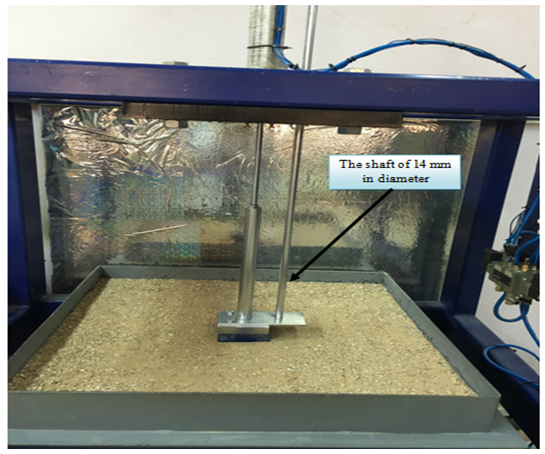 | Figure 4. The shaft of 14 mm in diameter |
2.4.2. Air Compressors System
- The compressed air system (Project Air brand), which consists of a 40 liter metal vessel with a pressure capacity greater than 10 bar, was used. The compressed air system consists of air compressor made of silicon aluminum alloy with air reducing valve and way valve. The compressor is driven by a 2.5 kW electric motor and is a single phase motor with a voltage of 220 V and a frequency of 50 Hz and a rotation speed of 1450 rpm.The compressed air system is equipped with pressure gauges and a controlled pressure valve in addition to an automatic electric control that operates and turning off the compressor which is controlled on a maximum pressure of 8 bars for turning off and 6 bars for operation.
2.4.3. Control System
- This system controls was the movement of the device under the effect of applied loads either monotonic or cyclic loading. The system consists of two directional valves one for manual operation and the second for auto operation with electric control, and the movement of the pneumatic cylinder is controlled by these valves and the electrical signal as shown in Figure 5. An electric panel is used to control these valves. This panel allows manual operation by two buttons; one for upward movement and the second for downward movement or automatically by means of timer and relays.
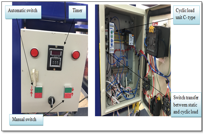 | Figure 5. Control system – a general view |
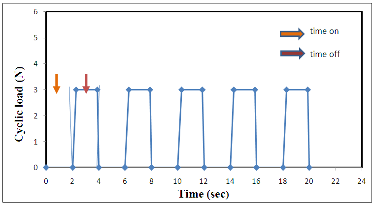 | Figure 6. Realistic load-time relationship |
2.5. Model Footing and Container
- Two steel foundations with 20mm in thickness were used with different foundation dimensions for circular footing with a diameter 100 mm and square footing (100mm100 mm).A soil container was used with inner dimensions of (700*700) mm and 800 mm in depth made as one piece, the container is made of (6 mm) thickness steel plate.
2.6. Instrumentation
- The settlement of the footing during the application of cyclic load was measured by using LVDT (Linear Variable Differential Transformer). The LVDT has a stroke of about 70 mm with an output signal ranging ±10 V with a normal 10 V DC power supply. The measurement was made at the surface of footing (from the edge). A special technique was used to ensure a firm connection between the LVDT and the upper surface of the footing. The system of data acquisition was utilized so that all data could be scanned and recorded automatically by using computer and data logger, as illustrated in Figure 7.
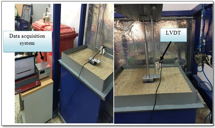 | Figure 7. Linear variable differential transformer (LVDT) |
3. Model Test Results under Cyclic Load
3.1. Applied Load Lower than Qall of Footing
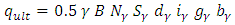
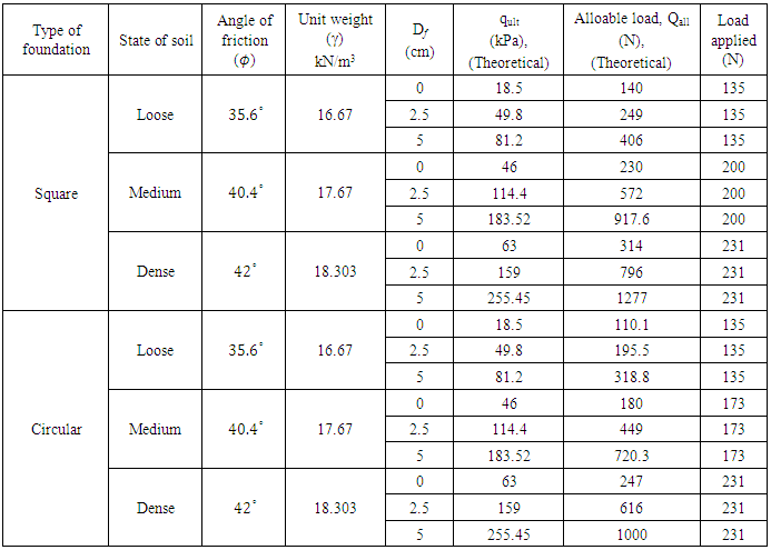
- A group of 54 model tests were performed on dry sand as a reference under cyclic load using sand of three different relative densities; 30%, 60%, and 80% which are corresponding to loose, medium and dense sand, respectively. For all model tests, the failure is defined as the load causing a settlement corresponding to 10% of the footing width depending on the failure criterion given by Terzaghi, (1943).To select the value of the applied load on the footing model, the theoretical ultimate bearing capacity of the footing was calculated according to the variables; relative density, angle of friction, depth of foundation, width of foundation and shape of foundation. The calculations were made based on Hansan equation (Hansan, 1970; Bowles, 1996):
 | (1) |
 = ultimate bearing capacity, c = cohesion of soil, q = surcharge (γ Df), Df = depth of the footing, Nc, Nq and Nγ = bearing capacity factors, B = width of foundation,γ = unit weight of soil,Sc, Sq, Sγ = shape factors,dc, dq, dγ = depth factors,ic, iq, iγ = inclination factors,gc, gq, gγ = ground factors, andbc, bq, bγ = base factors.
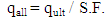 | (2) |
 | (3) |
 are equal to 0, so Equation (3) becomes:
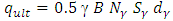 | (4) |
 | (5) |
|
3.2. Effect of Foundation Depth
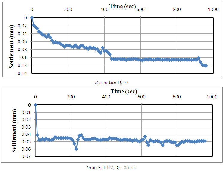
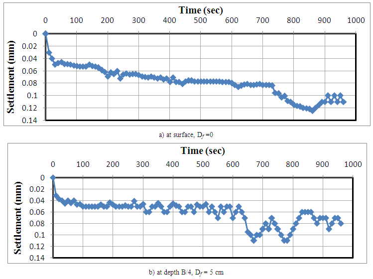
- The depth of footing is important parameter which governs the ultimate bearing capacity of the soil. In general, when the cyclic load applied on a foundation is lower than Qall , the other parameters such as the sand relative density R.D., foundation type, total time and velocity of device (rate of loading) were kept constant but the depth of the foundation is only changed.Three depths of foundation were tried;Ÿ at the surface of the soil, Ÿ at depth 2.5 cm (B/4) and Ÿ at depth 5 cm (B/2). The ratio of embedment depth of the footing to its width, called the embedment depth ratio, varies from 0 to 1 (Kazi et al., 2014). Through the results of laboratory tests, it can be noticed that the more the depth of footing (Df increasing), the soil settlement decrease as presented in Figures 8 to 13. In general, when other factors are remaining constant, the bearing capacity of the soil goes on increasing when the depth or width of the foundation increases as depicted by Dixit and Patil (2010).The total settlement of a footing continues to increase during the time of the load (dw) and reaches a maximum value (Smax) at the end of dwell time. During the decay period of the load, the footing rebounds to some degree.It is necessary to realize that the soil behavior is elastic, or else deformation will increase with each cycle of loading until the unstable soil behavior develops.During cyclic loading, the sand undergoes recoverable and irrecoverable strains. Under a given cyclic load, the recoverable strain is reasonable constant and the irrecoverable strain accumulates with number of cycles (Boyce, 1976, 1980; O` Reilly, 1985; O` Reilly and Brown, 1992). Failure of foundations is generally associated with the irrecoverable strains in soils. It is generally reported that the rate of accumulation of irrecoverable strains in soil is a function of cyclic stress and strain levels.
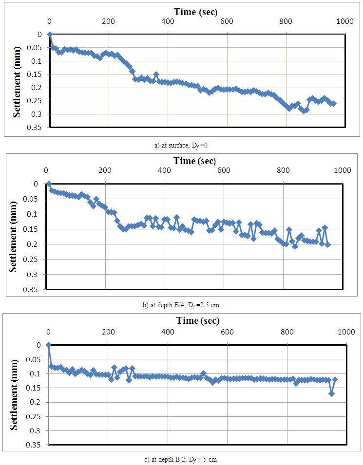 | Figure 8. Variation of settlement with time when the velocity is 5 mm/sec and R.D. = 60% for square foundation at different depths |
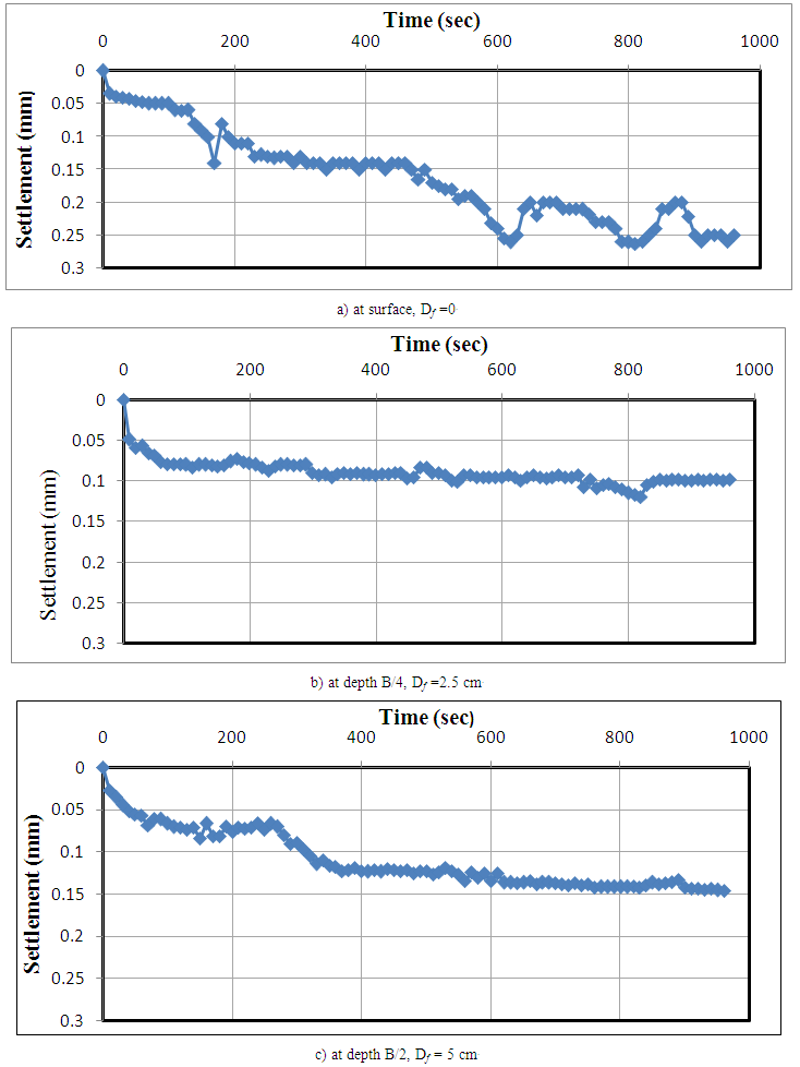 | Figure 9. Variation of settlement with time when used the velocity is 2.5 mm/sec and R.D. = 80 % for square foundation at different depths |
 | Figure 10. Variation of settlement with time when the velocity is 10 mm/sec and R.D. = 60% for square foundation at different depths |
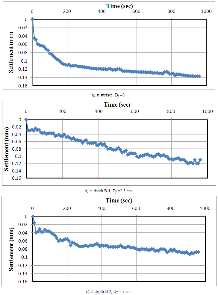
 | Figure 11. Variation of settlement with time when the velocity is 5 mm/sec and R.D. = 30% for square foundation at different depths |
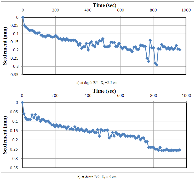
 | Figure 12. Variation of settlement with time when the velocity is 2.5 mm/sec and R.D. = 30% for circular foundation at different depths |
 | Figure 13. Variation of settlement with time when the velocity is 10 mm/sec and R.D. = 80% for circular foundation at different depths |
3.3. Effect of Rate of Loading
- It can be noticed that the effect of loading rate depends on the density of sand bed. In loose sand, the cyclic load settlement increases with the rate of loading, while in dense sand, the cyclic load settlement decreases with rate of loading. In the latter case, when the rate of loading increases, the sand particles do not have enough time to arrange themselves in denser state, so that the settlement becomes lower than that under lower rates.
3.4. Applied Load Equal to Qall of Footing
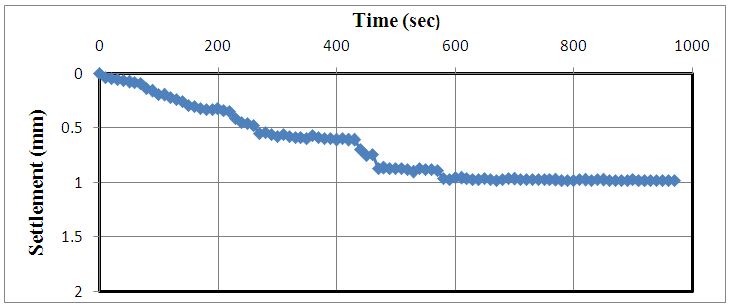
- In order to investigate the effect of the cyclic load amplitude on the foundation settlement, three model tests were performed on dry sand as a reference under cyclic load using sand of three different relative densities; 30%, 60%, and 80% which are corresponding to loose, medium and dense sand, respectively. The footing is placed at three depths. Figures 14 to 16 show that with continuous increasing load applied, there is increase in settlement with time.Several studies have been carried out to understand the behavior of model footings on sand deposits and subjected to cyclic loads. Raymond and Comos (1978) studied the behavior of model strip surface footing under vertical cyclic load and reported that the permanent settlement increased as both the number of load cycles and the magnitude of cyclic load increased.Based on cyclic triaxial tests on sand, Luong (1980) reported that the rate of increase in the permanent deformation with number of cycles, decreases if the cyclic load level is lower than a threshold value and increases if the cyclic load is higher than the threshold value. However, no method has been suggested for obtaining the threshold value. Furthermore, the safe limiting stress level for the cyclic loading has not been identified.It can be noticed that the accumulated cyclic settlement increases as the repeated (cyclic) load is increased. The response of footing under the first few cycles is a significant behavioral characteristic of footings and also; with increasing the number of cycle loads, the rate of footing settlement reduced significantly until its value becomes stable or failure occurred due to excessive settlement.The permanent deformation developed as a result of cyclic loading is an important factor to count when designing foundations in an environment matter where cyclic loadings are expected to occur, such as those in seismically active regions or offshore environments.It can be also noticed that the accumulated cyclic settlement is slightly affected by the sand relative density. This may be attributed to the uniform size of particles, so that small densification takes place during loading.
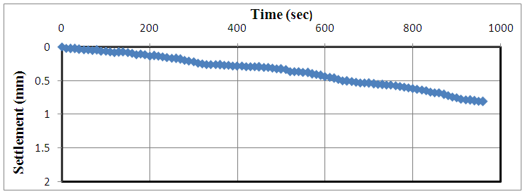 | Figure 14. Variation of settlement with time when the velocity = 5 mm/sec, square footing, R.D. = 30% and Df = 5 cm and Qapplied = Qall |
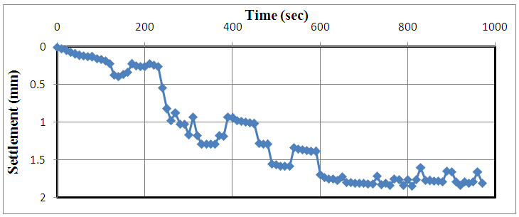 | Figure 15. Variation of settlement with time when the velocity = 5 mm/sec, circular footing, R.D. = 60% and Df = 2.5 cm and Qapplied = Qall |
 | Figure 16. Variation of settlement with time when the velocity = 5 mm/sec, square footing, R.D. = 80% and Df = 0 and Qapplied = Qall |
4. Conclusions
- 1. The more the depth of footing (Df increasing), the soil settlement decreases. In general, when other factors are remaining constant, the bearing capacity of the soil goes on increasing when the depth or width of the foundation increases.2. The total settlement of a footing continues to increase during the time of the load and reaches a maximum value at the end of dwell time. During the decay period of the load, the footing rebounds to some degree.3. The effect of loading rate depends on the density of sand bed. In loose sand, the cyclic load settlement increases with the rate of loading, while in dense sand, the cyclic load settlement decreases with rate of loading. 4. The accumulated cyclic settlement increases as the repeated (cyclic) load is increased.5. The accumulated cyclic settlement is slightly affected by the sand relative density. This may be attributed to the uniform size of particles, so that small densification takes place during loading.