-
Paper Information
- Previous Paper
- Paper Submission
-
Journal Information
- About This Journal
- Editorial Board
- Current Issue
- Archive
- Author Guidelines
- Contact Us
International Journal of Construction Engineering and Management
p-ISSN: 2326-1080 e-ISSN: 2326-1102
2013; 2(1): 23-31
doi:10.5923/j.ijcem.20130201.04
Evaluation of the Failure and Reinforcement of the Foundation in a 20 Storey Residential Building
 Abstract
 Reference
 Full-Text PDF
 Full-text HTML
F. Lopez-Gayarre 1, M. B. Prendes-Gero 2, M. I. Alvarez –Fernandez 3, F. L. Ramos-Lopez 4, L. Jorge Noval-Muñiz 5
1Department of Construction and Manufacture Engineering, Engineering School of Gijon, Campus de Viesques, Asturias, Spain
2Department of Construction and Manufacture Engineering. University of Oviedo – Politechnical University of Mieres, Asturias, Spain
3Department of Exploitation and Prospecting Mines, Mining Engineering School, University of Oviedo, Asturias, Spain
4Department of Physic. University of Oviedo Campus de Viesques, Asturias, Spain
5Architect. Jorge Noval, Architecture Studio, S.L. Gijón, Asturias, Spain
Correspondence to: F. Lopez-Gayarre , Department of Construction and Manufacture Engineering, Engineering School of Gijon, Campus de Viesques, Asturias, Spain.
| Email: |  |
Copyright © 2012 Scientific & Academic Publishing. All Rights Reserved.
In this study, we present the results of the forensic analysis and solution proposed for the foundation of a 20-storey building located in the center of the city of Oviedo (Spain), built between 1957 and 1962, and renovated in 2002. During a probe carried out in order to evaluate the original foundation, it was observed that the resistance of the ground was slightly less than that considered for the calculation, and therefore the foundation of the building had to be reinforced. In this paper, we present a detailed description of the problem; determine the source of the failure, present the solution adopted and the constructive process followed. After evaluating different solutions, we opted to construct caissons. In this manner, the foundation of the building was moved to a level with a more resistant layer of ground. The focus of this study is to present as a main cause of the failure the infiltration of sludge waters coming from a manifold located in the surrounding area of the building, which altered the subsoil and caused it to lose resistance. Also relevant is the constructive solution adopted to solve the problem. This study gives a detailed description of the construction process followed in order to be able to replace the original footing by other footing located at a depth of -3.75 m from the first level.Finally, we present the findings derived from the analysis and resolution of the problem.
Keywords: Forensic Analysis, Single Footing, Caissons, Pillar Supports
Cite this paper: F. Lopez-Gayarre , M. B. Prendes-Gero , M. I. Alvarez –Fernandez , F. L. Ramos-Lopez , L. Jorge Noval-Muñiz , Evaluation of the Failure and Reinforcement of the Foundation in a 20 Storey Residential Building, International Journal of Construction Engineering and Management, Vol. 2 No. 1, 2013, pp. 23-31. doi: 10.5923/j.ijcem.20130201.04.
Article Outline
1. Introduction and Background
- The building “La Jirafa” is located in the center of the city of Oviedo (Spain) and was built between the years 1957 and 1962. It was planned as a multi-purpose building to include a hotel, a social club, shops and offices. In 2002, the owners of the building decided to renovate it and transform it into luxury homes. The building has two sections separated by an expansion joint. The highest section of the building has 20 stories, including a floor partially below ground level. The lower floors still contain shops and an office of the postal service. The lower section goes up to the eighth floor (figure 1). The structure of the building is built with reinforced concrete frames.Initially, the rehabilitation was going to be carried out by renovating the facade, demolishing the internal partition and keeping the whole structure intact after repairing and reinforcing some beams and pillars.All that was added was a reinforced concrete central core that includes the two shaftsintended for the elevators. The jobs dragged on longer than initially planned because the technical management team detected problems in the original foundation of the building. The subsoil of the area consists primarily of loams, with an allowable stress of 0.35 to 0.45 MPa. The calculation of the original foundation was made based on such data. In order to check the foundation of the building, a probe was carried out on the sidewalk of the main facade of the building, in which we determined that the foundation was actually built on a clay layer with a reduced allowable stress of 0.20 to 0.30 MPa. The data obtained in the probe was verified by means of inspections carried out in the partial basement of the building. The technical management in charge of renovating the building decided to replace the existing foundation with a new foundation built at a depth of 3.75 m from the depth of the original foundation, in order to ensure an adequate transfer of stresses on the ground.This paper presents a detailed description of the problem considered and the solution adopted in order to solve it. Given the characteristics of the ground and the depth of the firm stratum, the solution adopted was to build caissons[1]. In order to reach the new firm stratum of the ground, the process of creating the caissons consisted of unloading the concrete pillars by means of an auxiliary metallic structure, using epoxy resins as a joint between the steel and concrete[2].This study begins with an analysis of the geology and hydrogeology of the area. In the following section, we present a detailed description of the problem posed by the original foundation of the building. In the fourth part, we explain the solution adopted and describe the constructive process that was followed. Finally, we present the conclusions obtained as a result of the work performed.
2. Geology, Hydrogeology and Geotechnics of the Area
- Cretaceous materials are predominant throughout the urban subsoil of Oviedo. These materials are of a carbonatated and silicilastic nature and have a capacity of approximately 200 m. On top of these materials, there are random deposits of materials from the Tertiary layer, of a fluviolacustrine nature formed by a basal conglomeratic section (with limestone from the Upper Cretaceous Age) on which there are deposits of white marly limestone, multicolored marls and more at the top, mixtures of marls and sandy clays.As shown in Figure 1, there are a series of subvertical faults in the surrounding area which tend to run in the direction of NW-SE and NE-SW.
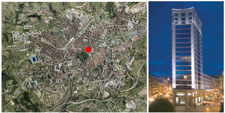 | Figure 1. Location and current height of the building |
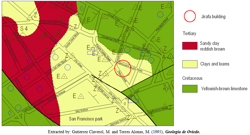 | Figure 2. Geological environment of the building “La Jirafa” |
3. Description of the Problem
- Initially, the renovation of the building was going to be performed by keeping all of the original reinforced concrete structure intact, repairing and reinforcing only the areas that presented a pathology. Once the interior partition was demolished, a detailed inspection of the building was performed, observing that the beams and pillars of the structure were in generally good condition. The porosity of the concrete and the forward movement of the carbonatation front made it advisable to protect the concrete in order to guarantee the long-term durability of the structure. The list of the most significant damages found was as follows:→There was a 15 cm slump in the main facade of the building due to poor positioning of the liner plates. →In the floor partially below ground level, the frame of some of the pillars was bent and exposed to the air due to the effect produced by the local buckling of the piece.→In some areas of the underside of the slab, the framework was exposed to the air due to the construction system used. The slabs were built using 15 cm thick concrete joists in situ. In the areas affected, a poor performance during the construction was the cause of the damage mentioned.→One of the beams of the basement had a crack due to overstrain of the concrete. Therefore, we proceeded to brace the beam in order to repair and reinforce it.→With the numerous reforms made throughout the life of the building, steel bars were cut from the frames of the slabs on some of the floors.In addition to the damages already mentioned, the study of the concrete structure revealed that 85% of the structure was already affected by carbonatation[3]. For this reason, the construction project managers decided to reinforce the structure of the building by lining the beams and pillars of the entire structure using laminated steel angle iron and fasteners[4].On the other hand, the slabs, affected by the aforementioned damage, were demolished and replaced by some new steel-concrete mixed slabs.Due to the current regulations in force in Spain regarding the conditions for protecting against fires[5], a new elevator shaft as well as a new pressurized staircase needed to be added, which is why the structure of the building had to be modified. This reform required the placement of new beams and pillars.In order to verify the suitability of the existing foundation to the reforms planned in the building, and on the other hand, in order to calculate the foundation footing for the new pillars, the building was comprehensively inspected. The foundation system used in constructing the building was superficial reinforced concrete single footing without any bracing. The depth of the foundation was located at 1 m with respect to the grazing level corresponding to the steel of the main facade of the building.In order to calculate the original foundation, the technical management team determined that the allowable stress of the ground was 0.35 MPa. These values were established by the designers based on the information obtained from a geotechnical study carried out in the area prior to constructing the building. The estimates made by other designers were also taken into account for the design and calculation of the foundations in the buildings located in the surrounding area. In an initial inspection of the original foundation, it was determined that for the most unfavorable hypothesis of wind during the molding process, some of the footing transferred stresses measuring 0.45 MPa to the ground. Taking the geology of the area into account[6],[7], it had been considered that the building's foundation lay on carbonatated red loam of the Cretaceous layer, with an allowable stress of 0.35 to 0.45 MPa. Although in order to calculate the foundation of the building, 0.35 MPa was taken as the value of the allowable resistance of the ground, its greater resistance a priori guaranteed the stability of the foundation.In order to verify these extremes, another geotechnical study was carried out. To do so, probing was conducted on the sidewalk of the main facade of the building. The results obtained determined that the layer of ground where the foundation was laid was built with reddish marly clays, caused due to the alteration of the loams, which was likely due to the sludge waters, with an allowable stress of 0.20 to 0.25 MPa—slightly less than that considered for the calculation. Figure 3 represents a section of the ground obtained based on the data from the probe carried out. The analysis carried out on the sample of water collected in the subsoil, in an inspection performed next to one of the center footings, a slight load of fecal contamination is observed where it appears that the water is of a groundwater source, although infiltrated by the rupture of one of the manifolds in the area along the southeast-northeast boundary. This manifold was repaired in 2008.Having examined the results obtained, the interior foundation of the building was inadequate. The perimeter footing did not present any type of problem. From the same study, it appears that a layer of ground with an allowable stress greater than 0.35 MPa was located at an average depth of 2 m with respect to the depth of the original foundation.
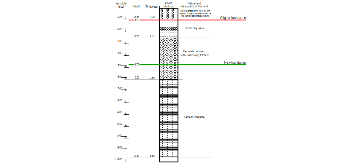 | Figure 3. Section obtained on the ground by means of the probe carried out |
4. Solution Proposed
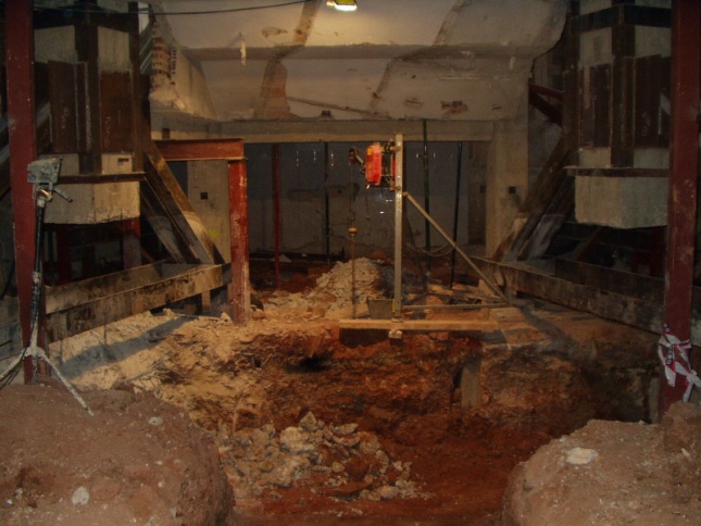
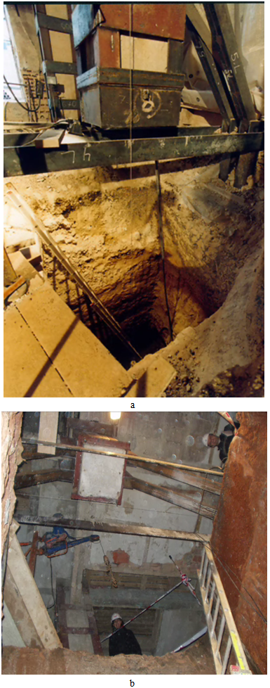
- Reinforcement of the foundation by means of micropiles was ruled out due to the cost, although also due to problems with space to accommodate the machinery needed for the implementation of existing micropiles in the partial basement.Neither was it considered suitable to make an addition of the footing, because it is considered that they might produce excessive settling or because the increased footing would take up too much space in the new structural distribution being proposed.In order to solve the problem raised regarding the foundation of the building, caissons were built, displacing the foundation at a support surface located at a depth of 4.75 m. In this manner, it was possible to add on to the building with a second floor in the basement. To do so, it was necessary to unload the interior footing of the building by means of an auxiliary metallic structure that was supported on temporary footing built for such purpose, as observed in figure 4.The auxiliary metallic structure was attached to the pillar by means of a seal using epoxy resins (Figure 5). The epoxy resins used[2] adhere to concrete greater than 3 MPa and to steel 17 MPa. Once hardened, its resistance to compression is between 80 and 90 MPa, and resistance to flexotraction varies between 30 and 40 MPa.
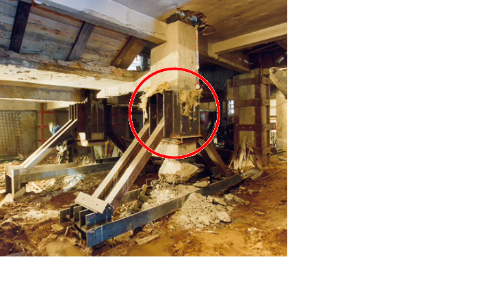
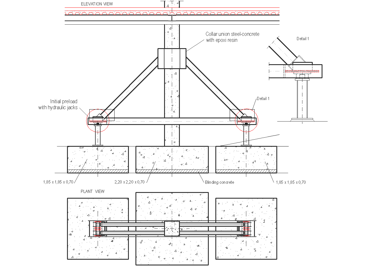 | Figure 4. Auxiliary structure for the unloading of the original pillars |
 | Figure 5. Joint seal between the auxiliary structure to the pillar using epoxy resin |
 | Figure 6. Cutting of the pillar using a wire saw |
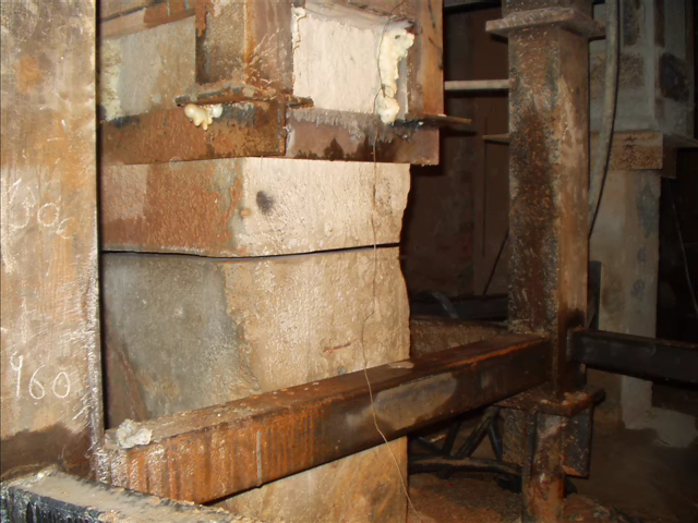 | Figure 7. A sectioned pillar |
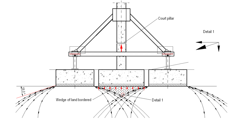 | Figure 8. Interaction of the pressure bulbs of the auxiliary footing |
 | Figure 9. Demolition of the lower part of the pillars and the original footing |
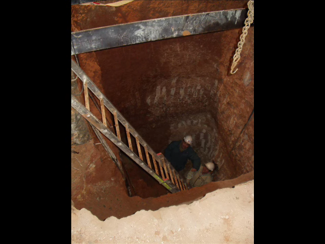 | Figure 10. Caisson |
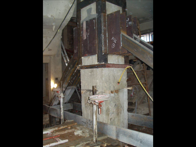
 | Figure 11. Sectioned pillar, caisson, auxiliary structure and footing |
 | Figure 12. Pillars finished using metallic angle irons and fasteners |
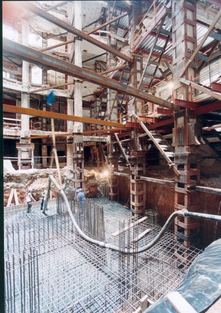
 | Figure 13. Foundation zone reinforced using caissons |
5. Conclusions
- We can rule out a poor design of the foundation, given that it has behaved correctly for more than 40 years.The analysis of a water sample collected in the surveys carried out on the subsoil of the building reveals the presence of fecal contaminants, confirming the sludge in the foundation of the building due to the rupture of one of the manifolds in the area. Due to this situation, the resistance of the support surface of the foundation has decreased, given that the entrance of sludge waters has changed the carbonatated red loam of the Cretaceous layer. These loams have become red clay loams with an allowable stress that is slightly less than that of the original loams. Expanding the foundations is not considered to be a good solution given that the dimensions of the footing would not be feasible on the floor of the building. After eliminating micropiles due to financial reasons, caissons appear to be the most suitable solution.The use of epoxy resins as elements to join steel and concrete supporting large stresses present a good behavior.The unloading of the pillars must be done gradually and in a controlled manner, using hydraulic jacks in order to avoid asymmetry during the unloading, which would cause additional stresses that would weaken the structure. Once the pillar is cut, the ground confined between the pressure bulbs corresponding to the auxiliary footing used for unloading the pillars undergoes an increased compression stress that tends to lift up the original block and the section of lower pillar that was previously cut. In order to prevent sludge water from entering the stratum of loamy soil where the foundation is supported, it is advisable to set up a center and peripheral drainage system. The evacuation of such waters must be carried out using a pump.