Oluwole. O. O 1, Akindahunsi. A. A 2
1Mechanical Engineering Department, University of Ibadan, Ibadan
2Civil Engineering Department Obafemi Awolowo University, Ile-ife
Correspondence to: Oluwole. O. O , Mechanical Engineering Department, University of Ibadan, Ibadan.
| Email: |  |
Copyright © 2012 Scientific & Academic Publishing. All Rights Reserved.
Abstract
The building industry in any economy can truly be an index of the vibrancy of the economy by the amount of active development, innovation and re-designing occurring in that sector. Development, re-designing and new innovative designs can only be brought about by active research and development(R&D), a sine-qua-non in the quest for safe designing and development. Modeling and simulation is a veritable tool for R &D. This paper presents the multifaceted use of modeling and simulation as decision tools for engineering infrastructural design using a single storey building and a trapezoidal dam as case studies.
Keywords:
Safety, Infrastructures, Modeling, Simulation
1. Introduction
Safety in engineering infrastructures comes to the fore at this time when the collapse of buildings has become incessant. Collapsed buildings fall into two categories: old, dilapidated buildings and new buildings being erected. Solutions to the problems of new buildings collapse has been proffered on many occasions by stakeholders[1,2,3,4]. These are: enforcement of building standards, employment of qualified personnel to handle building projects, eradication of corruption among housing development personnel that ought to monitor and issue approvals, placing registered engineers at relevant ministries and parastatals. (It should be noted that many times engineering ministries- Works and Housing, Power and Steel, Telecommunications etc are saddled with non –engineers as ministers and Director Generals. On the issue of collapse of dilapidated buildings, these could be solved by life- span analysis(even reinforcement rods do corrode in concrete!), proper monitoring and advice by Housing agencies in the local governments(who should know the history and monitor these buildings) to the owners of old and dilapidating structures. Advice should be in form of telling the stakeholders to renovate the building or totally pull down and re-build. In this way, I believe these issues of collapse will be eradicated or seldom happen. This paper presentation is aimed at empowering qualified builders and civil engineers and monitoring engineers to be able to rapidly model and simulate structures within hours so as to confirm whether drawings will work or not. Modeling and simulation in the building industry is now an integral part in economical production of new designs[5]. The building engineer is assisted through modeling and simulation in translating paper designs into manufacturing designs. The engineer is able to determine among other things the correct placement of reinforcements and pillars. He is able to simulate the impact of wind forces, weight loads and impact loads on the structures thus able to make intelligent decisions as to possible defects initiation in the structure[6]. The use of computers in civil and structural engineering is well established. Behaviour of novel designs cannot be ascertained without subjection of designs to simulations of behaviour in true-life situations using mathematical models. Stress-strain behaviour and hence mode of possible shear could be simulated in concrete structures-buildings, bridges, houses, dams etc.
1.1. Simulation Software Development
Software development in the building services in many instances are built based upon the finite element method[7,8,9]. Both private and commercial software have sprung up. Some are multipurpose like Ansys[10], Nastran[11] and Matlab[12]. Others are specific purpose software like (i) RING; a free analysis program for single and multi-span masonry arch bridges developed at the University of Sheffield, UK. (ii) FBEAM ; Free software for the design of fabricated composite and non-composite steel beams (with web openings) to BS5950. Produced by the Steel Construction Institute,UK (iii) MARC/Designer; free, fully functional finite element analysis software used for Linear static stress, buckling analysis, steady state heat transfer and modal analysis by MARC Analysis and Research Corp, Austria.(iv) UniPhase 2.1; free program to assist in selecting soil density and calculating phase system parameters such as void ratio, dry density, and degree of saturation developed by unisoft ltd, UK(v) Rockgrout ; free suite of programs about cement grouting in rock foundations for dams and other heavy engineering structures by Clive Houlsby.What makes some of the above software stand out is the graphics user interface(GUI) making results translated into visual display in seconds(Figs 1-4). Simplicity of use, accuracy of results and justifiable cost of software acquisition are other attractive points.
1.2. Flexibility of Program
General purpose programs prove to be very unwieldy and lack depth and it is better when programs are focused on specific problem areas eg. elasticity, deflection, structures etc rather than lumping all together in one software package.
1.3. Graphics Interphase
Interactive graphic user interphase(GUI) using programs like the C++ builder, Visual Basic and MatlabR make programs user friendly. However, many real life programs in 3-dimension still have to be connected to plotters for graphic displays.
1.4. Accuracy of Results
Accuracy of results are affected by the accuracy of the numerical method and the fineness of the meshing.
1.5. Stability of Numerical Method
The explicit finite difference and the finite element methods are known to introduce inconsistencies in the results when the time step is too large.
2. Methodology
2.1. Finite Element Modeling
The material was considered isotropic and two dimensional (Figure1). The material was subjected to volume loading in the y-direction by the concrete floor, pillars and the roof. The values of the loads applied are:- Decking reinforcement weight=2000kg;weight on deckings=0kg; top decking weights=1500Kg;Side Reinforcement=2500KG1st decking weight=2000kg; Basement weight=3000kgSteel properties;E=450X106Kgf/m2.Poisson ratio=0.3;Concrete properties;E=200X106 Kgf/m2; Posson ratio=0.7The Matlab pdetool graphics user interface was used in the finite element modeling of the material. Three-nodetriangular elements were used in meshing(Figure2) and the normal finite element equation applicable to elasticity problems were applied thus: 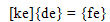 | (1) |
Where | (2) |
 | (3) |
 | (4) |
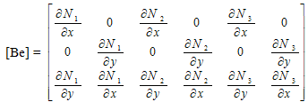
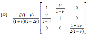
for plane strain condition.N1, N2 and N3 are shape functions for three-node triangular elements.x and y are the directions in which the forces are actingE = Youngs modulus of elasticity = Poisson ratio {f e} = element force vector {de}= element displacement vector
2.2. Assembly of element equations into global equation and Solving for displacements
The elemental equations were assembled and solved using the global equation: | (5) |
Where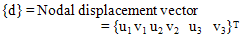 | (6) |
2.3. Solving for Strains, Stress and Shear stress and strains
Solving for strains, we used the kinematic equation relating strains to displacements which is stated as: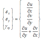 | (7) |
Solving for stresses, we used the constitutive equation between stress and strain | (8) |
For shear stresses, equations of equilibrium of forces acting on two-dimensionalContinuum was used. These are: 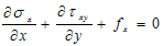 | (9) |
and 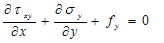 Where
Where  are stresses acting in the x, y directions and Shear stress respectively
2.4. Case Studies
Case 1: Single Storey Building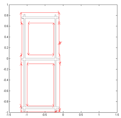 | Figure 1. A single deck building with roof and deck all reinforced with steel rods |
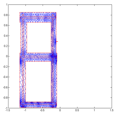 | Figure 2. Meshing the single deck building |
Reinforced concrete (RC) is one of the most important building materials and is widely used in many types of engineering structures. The economy, the efficiency, the strength and the stiffness of reinforced concrete make it an attractive material for a wide range of structural applications. The ultimate objective of the designer is to create structures that are safe and economical. The safety and serviceability assessment of the structures necessitate the development of accurate and reliable methods and models for their analysis. In addition, the extent and impact of disaster in terms of human and economical loss in the event of structural failure prompt designers to check the design thoroughly[15]. The main reason for adding steel reinforcements is to improve the tensile behavior and to obtain a ductile material in tension[13]. The elastic perfectly plastic model is widely used for idealization of reinforcing steel. Modeling is one of the most important areas for finite element analysis. Accuracy in the modeling of geometry, loads, material properties, boundary conditions, and other structural properties are of absolute necessity for close numerical idealisation of the actual member/structure[14]. A; Wind gale force of 0KG;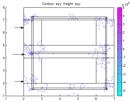 | Figure 3. Stresses in y-direction. We can see stresses concentrated on pillars, deckings and in the reinforcements |
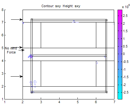 | Figure 4. Shear stress as a result of stresses on building; None to threaten building |
B: Case of Wind gale force of 20,000N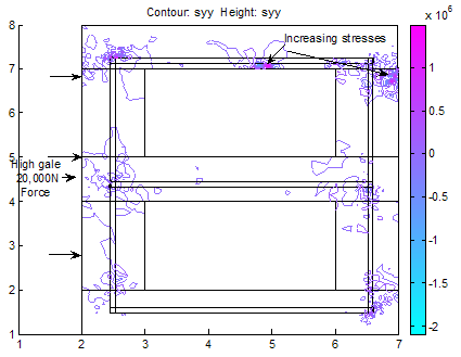 | Figure 5. With a wind gale force of 20,000N, the top roof decking is showing signs of increasing stresses but not enough to threaten the building as the stresses in the y-direction do not exceed fracture stress for steel reinforcement and concrete. However, we can immediately see the areas of stress concentrations |
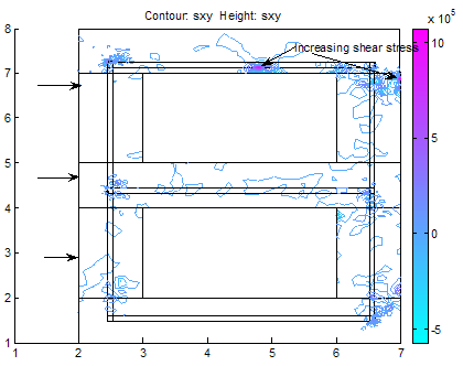 | Figure 6. Shear stresses as a result of the heavy wind gale force showing spots where failure will likely initiate when gale forces rise above strength of building. When this occurs, buckling will first initiate in the top decking reinforcement and in the concrete pillar in the adjacent side opposite to the wind gale direction |
Case Study(2) : Trapezoidal DAMDams are massive structures built up with stone, earth or concrete across a river or stream for the purpose of storing water. Dams could be trapezoidal, triangular or rectangular [16].Dam failures should be guarded against in design. Possibilities of dam failure happen when dam begins to slide along its base, or when it shears at its weakest section, or overturns or failure due to overwhelming compressional or tensional forces. Eccentricity of the resultant force acting on the dam determines where the maximum forces are directed ; either towards the heel or the toe.Problem FormulationThe material was considered isotropic and twodimensional as in case1 . The material Subjected to 50000000Kg Volume force in Y-direction=Wt of Dam and 50000Kg force at water front. The Finite Element formulation is as expounded in case1 for plane strain conditions.
4. Results And Discussions
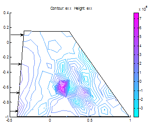
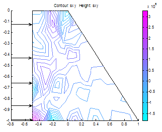
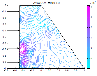
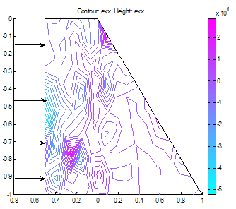
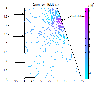
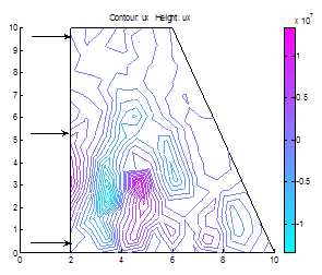
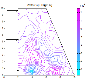
(Case Study 1)The results for the single storey building are presented in Figures 1-6. Figures 1-4 present the scenario where there is no wind force blowing on the house and only the weights of the deckings, pillars and basements are considered in the analysis. Figure 3 shows the stress distributions in y-direction. Stresses were observed concentrated on pillars, deckings and in the reinforcements. Figure4 shows the shear stresses as a result of the stresss acting on the building. The shear stresses were observed to be not threatening. The scenario was altered as presented in Figure5 showing streses acting on the building under the influence of a wind gale force of 20,000N. The top roof decking is showing signs of increasing stresses but not enough to threaten the building as the stresses in the y-direction do not exceed fracture stress for steel reinforcement and concrete. However, we can immediately see the areas of stress concentrations. Figure 6 shows the spots where failure will likely initiate when gale forces rise above strength of building. When this occurs, buckling will first initiate in the top decking reinforcement and in the concrete pillar in the adjacent side opposite to the wind gale direction. With this information and a play of possible scenarios, proper design parameters can be made before final design of building. (Case study 2)The results ares presented in Figures 7-22 showing different scenarios in the design of a trapezoidal dam. Figure.7 shows the 2-D geometrical presentation of the trapezoidal dam on the Matlab pdeGUI and its triangular meshing(Figure.8). SCENARIO_1: Base Length =2*(Top Length) and (Base Length> Dam Height).Figs. 9-15 show the stress and strain distributions for a design where base length =2*(top length) and base length is greater than the dam height(base length> dam height). Figs 9-12 present the x and y-stress and strain distributions in the body of the trapezoidal dam. It could be seen that there is a concentration of stress and strain at the centroidal portion of the dam. This clearly showed where the stresses are concentrated in this kind of design. Figures 13 and 14 show the shear stress and strain distributions in the dam matrix. The shear stress and strains were observed to be in the direction of the dam toe. The direction of the shearing stress and strain shows the eccentricity of the resultant forces acting on the dam. Figure 15 presents the Von Mises stress which is close to the centroid of the dam. This shows the area most susceptible to shear. This dam design is very stable. SCENARIO_2: Base Length=3*Top Tength and (Base Length> Dam Height).Figures 16-19 show the various stress and strain distribution in this kind of dam design. It shows the forces directed towards the heel. This shows that shearing would occur near the heel of the dam as shearing forces overcome the bulk strength of the dam. Careful consideration should be given to these forces in design so that at no time will the resultant forces overcome dam body forces neither should shearing forces be higher than dam concrete strength.SCENARIO_3: Height> Base and Base Length<2*Top Length.In this scenario, the dam will likely shear at thinnest region as shown in Figure 20. This is a very unstable design and could lead to overturning of dam.SCENARIO_4: Base Length =2*(Top Length) and (Base Length< Dam Height).This is a variant of scenario_1. In this case(Figs. 21 and 22), the dam height is greater than the base length albeit slightly. The centroid could be seen moving towards the dam heel(Figure21) and the shear stresses were observed directed to the dam toe stretching from the centroidal region. A sectional shear in the midsection of a dam could be very disastrous.Stability of the DamsThe designer should convince himself or herself as to the structural soundness of the type of design proposed for specific dam locations. Scenario_1 could be seen to be very stable. However, if failure should occur due to stress effects, the failure would start from the centroidal part of the dam directed to the dam toe.In Scenario_2 failure would not occur easily because shear could be managed here as the peeled of basal portion of the frontal section of the dam which could be easily maintained.Dams need to be monitored from time to time so as to ascertain the structural integrity of the dam. This could be done using non-destructive testing methods(NDT’s) where internal cracks and weaknesses could be detected. 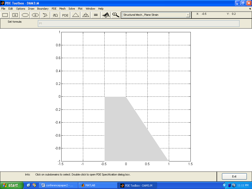 | Figure 7. A trapezoidal dam |
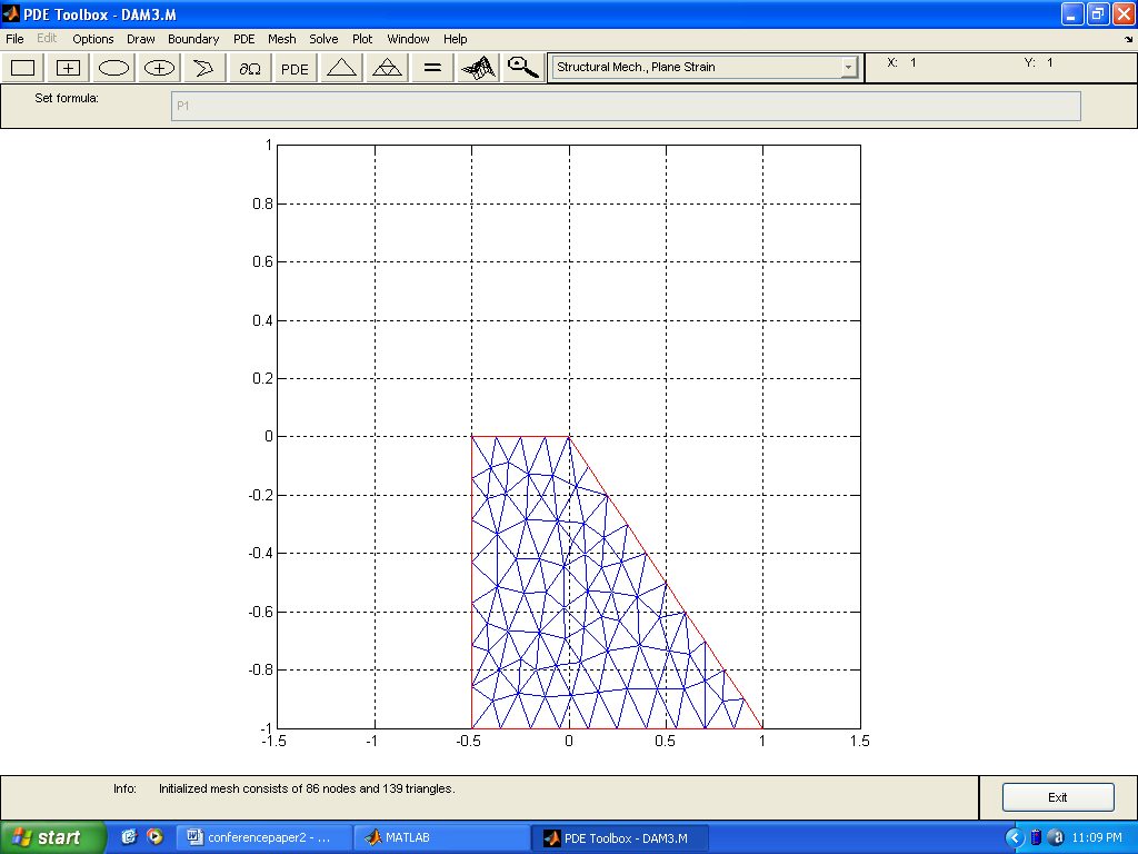 | Figure 8. Meshing the trapezoidal dam |
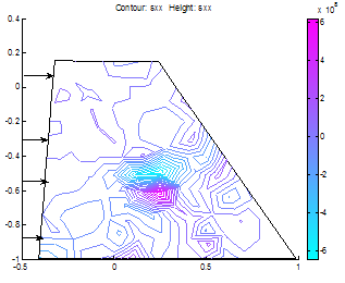 | Figure 9. x-stress distributions where base length =2*(top length) |
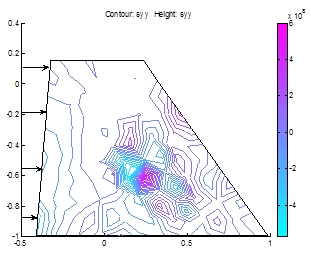 | Figure 10. y-stress distributions Notice the intense concentration near the centroid |
 | Figure 11. x-strain distribution in the dam |
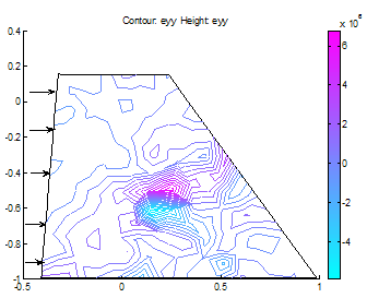 | Figure 12. y-strain distribution in the dam |
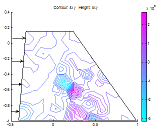 | Figure 13. shear stress distribution in the dam; notice the stress direction to the toe |
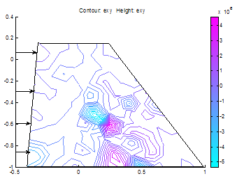 | Figure 14. Shear strain distribution in the dam |
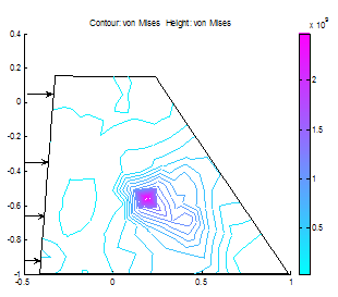 | Figure 15. Von-mises stress |
 | Figure 16. Shear stress directed towards the heel where base length=3*top length |
 | Figure 17. x-stress distribution in the dam |
 | Figure 18. x-strain distribution in the dam |
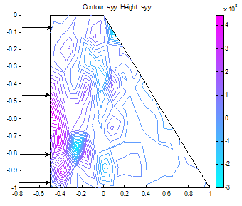 | Figure 19. y-stress |
 | Figure 20. Shear stress distributions where Height> base and base length<2*top length. Dam will likely shear at thinnest region if the situation arises |
 | Figure 21. Centre of gravity in a situation whereBase Length =2*(Top Length) and (Base Length< Dam Height) |
 | Figure 22. Shear stress in a situation where Base Length =2*(Top Length) and (Base Length< Dam Height) |
5. Conclusions
The foregoing has shown the usefulness of even simple 2-D modelling in verification of simple design problems using MATLAB(R). The time taken in modeling using requisite sotware is a time well spent and could double up even in conservative usage as a verification tool where manual calculations are still prefererred. However, it’s comes in handy as very reliable decision making tool when the real life situation is fully captured in the modelling process which is what every engineer should strive to attain regardless of factors of safety.
References
| [1] | Adebajo.K(2005) ‘A position paper by the Nigerian Institution of Structural Engineers (NIStructE), a division of The Nigerian Society of Engineers (NSE) on Recent Structural Collapses in Nigeria and the prevention of future incidences’. 3-day National Workshop on Collapse of Buildings and Engineering Structures, Abuja, Aug.5, 2005. |
| [2] | Ayininuola, G.M. and Olalusi, O.O.(2004) ‘Assessment Of Building Failures In Nigeria:Lagos And Ibadan Case Study’ AJST, 5(1),73-78. |
| [3] | Nigerian Institute of Architects(2001) ‘Architects decry spate of collapsed buildings’ Nigeria World Newspapers, November 14, 2001 |
| [4] | Uzokwe.A.O (2001) ‘Rising Incidence Of Building Collapse In Nigeria; Any Remedy?’ Nigeria World Newspapers, Dec. 2001 |
| [5] | Enercalc(2012) ‘Fastframe’ http://www.enercalc.com/support/downloads.asp |
| [6] | Whitman.H.G(2012) ‘ Structural Engineering Analysis software’ http://www.fseas.info/ |
| [7] | Cadre(2012) ‘CADRE Lite 2.1’http://www.cadreanalytic.com/cadrelit.htm |
| [8] | Grape(2012) ‘GRAPE GBW16’ http://www.grapesoftware.mb.ca/ |
| [9] | Reken(2012) ‘ ATLAS 1.20’ http://www.rekenwonder.com/atlas.htm |
| [10] | Ansys(2012) ‘Ansys 14.0’ www.ansys.com |
| [11] | Nastran (2012) ‘Nastran’ www.nastran.com |
| [12] | Mathworks (2012) ‘MATLAB®’ www.mathworks.com |
| [13] | Siddique, M. A and Abdur Rouf, M. D, (2006)“Effect of Material Properties on behavior of over-Reinforced Concrete Beams” Asian Journal of Civil Engineering (Building And Housing) Vol. 7, No. 2 Pages 195-204 |
| [14] | Thomée, B, Schikora, K and Bletzinger, K. U, (2005) “Material Modeling of Steel fiber Reinforced Concrete” EUROMECH Colloquium 460 Numerical Modelling of Concrete Cracking. Innsbruck, Austria. |
| [15] | Das, S and Hadi, M. N. S., (1996)“Non-Linear Finite Element Analysis of Reinforced Concrete members using Msc/Nastran” MSC World Users’ Conference |
| [16] | Rajput.R.K(1998) ‘Fluid Mechanics’ S.Chand and Company, New Delhi.pp.139-149 |
 Abstract
 Reference
 Full-Text PDF
 Full-Text HTML