-
Paper Information
- Next Paper
- Paper Submission
-
Journal Information
- About This Journal
- Editorial Board
- Current Issue
- Archive
- Author Guidelines
- Contact Us
International Journal of Agriculture and Forestry
p-ISSN: 2165-882X e-ISSN: 2165-8846
2014; 4(3): 145-153
doi:10.5923/j.ijaf.20140403.01
Air Velocity Produced by Different Types of Mixing and Ceiling Fans to Reduce Heat Stress in Poultry Houses
 Abstract
 Reference
 Full-Text PDF
 Full-text HTML
Amani Al-Dawood 1, Wolfgang Büscher 2
1Ph.D. in Animal Physiology, Hygiene and Environment, Researcher at the National Center for Agricultural Research and Extension (NCARE), Jordan
2Prof. of Livestock Technology, Department of Livestock Technology, Institute of Agricultural Technology, University of Bonn, Bonn, Germany
Correspondence to: Amani Al-Dawood , Ph.D. in Animal Physiology, Hygiene and Environment, Researcher at the National Center for Agricultural Research and Extension (NCARE), Jordan.
| Email: |  |
Copyright © 2014 Scientific & Academic Publishing. All Rights Reserved.
Poultry sector is still facing many problems due to heat stress during the periods of high temperatures. These include high mortality due to heat stroke, low chicken's growth rate, body gain, feed consumption and feed efficiency. However, air velocity is a main factor involved in thermoregulation. To overcome high temperature, it is necessary to increase the rate of air movement over the chicken. Fans can play an important role in the ventilation of poultry houses. Therefore, the present study aimed at investigating fan performance and air distribution and velocity by two different types of mixing fans (M4E/40 and M2E/40) and ceiling fans (PV60 and PV36). The effect of fan's height and tilt angle on air velocity in the bird’s area was presented. The study was conducted in an experimental building at the Institute of Agricultural Engineering, University of Bonn, Germany. The results indicated that air velocity produced by M2E/40 was significantly greater than M4E/40 with a mean of 3.94 m/s vs. 2.18 m/s, respectively (F=1.32; P<0.05). Overall, in all measuring locations the air velocity produced by fans was significantly low, and then increased until the 4th and 8th m of distance, and hereafter decreased until the 10th m for both M2E/40 (F=9.57; P<0.05) and M4E/40 at both tilt angles of 60° and 55° (F=11.77; P<0.05). The air velocity produced by M4E/40 was significantly greater at 60° than 55° with means of 1.11 m/s vs. 0.58 m/s, respectively (F=5.386; P<0.05). The air velocity produced by PV60 was 1.5-fold greater than PV36, but it was not significantly different with means of 1.56 m/s vs. 1.036 m/s for both fans, respectively (F=0.246; P=0.184). It is to be mentioned that an air velocity of 1.5-3.0 m/s is the optimal to achieve an optimal birds' performance under very hot conditions. In the current study, this optimal air velocity was obtained at different distances and measuring locations for all fans tested. In conclusion, agricultural fans used in this study could provide adequate air velocity, which can decrease the effective temperature inside poultry houses. Selection of fan location and modifying of fan's tilt angle are very important points to be taken into account to obtain the best air distribution and velocity to prevent heat stress effect on birds.
Keywords: High Ambient Temperature, Chicken, Cooling System, Tilt Angle, Air Distribution, Agriculture Technology
Cite this paper: Amani Al-Dawood , Wolfgang Büscher , Air Velocity Produced by Different Types of Mixing and Ceiling Fans to Reduce Heat Stress in Poultry Houses, International Journal of Agriculture and Forestry, Vol. 4 No. 3, 2014, pp. 145-153. doi: 10.5923/j.ijaf.20140403.01.
Article Outline
1. Introduction
- The raising of livestock for meat has been increasing in nearly all the industrialized countries since 1950's and today accounts for at least half of the total amount of agricultural output in every industrialized country [1]. Current global livestock production is growing more dynamically than any other agricultural sector around the world [2]. The poultry sector continues to be a major protein supplier to the world. Over the last years, world chicken meat and hen eggs' production have shown an accumulative increase [3, 4]. Poultry sector faces many problems, in which one of them is associated with the development of an intensive poultry industry in countries with a hot climate, where heat stress is a main problem during periods of high environmental temperatures. Even in some temperate climates, there is a danger that broiler chicken will die of heat stroke if they suddenly exposed to unusually high environmental temperature [5, 6]. High temperature influences intake, digestion, absorption and metabolism of energy of chickens [7], and resulted in a high mortality and low performance of the chickens [5, 8, 9]. The main environmental factors affecting performance of broiler chickens are ambient temperature, relative humidity, air velocity [10], and air quality such as oxygen concentration, carbon dioxide, ammonia, dust and microbial contamination [11]. Air velocity is one of the main environmental factors involved in thermoregulation, especially at high ambient temperatures. Convective heat loss increased significantly with increasing air velocity [12]. To overcome high temperature, it is necessary to increase the rate of air over the flock. This could be achieved by mechanical ventilation in closed housing [13]. Optimum poultry production requires a housing environment that offers well-distributed ventilation within the house [14]. One of the most effective ways of cooling birds during hot weather is to have indoor fans that either can blow the air around or can be directed onto the birds [15]. Agricultural fans are simple and inexpensive way to create air circulation, and could play an important role in ventilation of poultry houses and moving the air inside them, thus reducing the side effects of heat stress. The selection of fan location is a key point to be taken into account to obtain the best air distribution, and to avoid the expecting problems that can be faced by labour inside the poultry houses [16]. Therefore, the current study aimed at investigating the performance and air distribution by four types of mixing and ceiling fans. The effect of fan's placement height, tilt angle and measuring location on air velocity at the bird’s area was thoroughly determined.
2. Materials and Methods
2.1. Fans
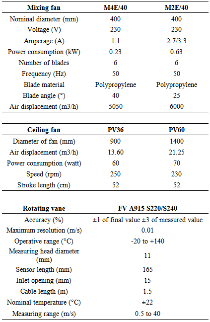
- The used fans in this study were of the type, Multifan Mobile and produced by Vosterman Ventilation B.V. Company. They are easy to transport with a wide range of applications, double wire-guard, motors with thermal protection and vertical blowing direction is possible. Mobile fans can be mounted horizontally and vertically. The capacity of the fans is controllable in a continuously variable way by changing the number of revolutions of the motor via the main voltage. The mixing fans, M4E/40 and M2E/40 were used in this study, and their characteristics are listed in table 1. In addition, two ceiling fans of the type PV36 and PV60 were used. PV fans have aluminium blades, which are matched and balanced to provide a smooth air delivery and wobble free performance. The technical data of the used PV fans are summarized in table 1.
|
2.2. Measuring Air Velocity
- An anemometer of the type ALMEMO 2290-4S was used in this study. ALMEMO measuring instrument can acquire virtually any measurable variables and master any measuring task. When measuring flows using ALMEMO sensors, the ALMEMO instrument provides important data functions for averaging and for volume flow measurement. For measuring the flow velocity, rotating vane of the type FV A915 S220/S240 with technical data mentioned in table 1 was used. It consists of a disc of angled vanes attached to a rotating spindle. The speed at which the vane assembly rotates is a measure of the air velocity. The flow velocity is determined through a frequency measurement. The advantages of this type of vane are high accuracy at medium flow velocities, medium ambient temperatures and insensitive to turbulent flows.
2.3. Experimental Procedure
- The experiments were conducted in an experimental building at the Institute of Agricultural Engineering, University of Bonn, Germany. In order to determine the fan performance, different parameters were taken into account namely; fan placement height, fan tilt angle, measuring location and distance from the fan. Velocities were measured using the fore-mentioned anemometer and rotating vane. When the fans were located at the floor region, the air velocities produced by M4E/40 and M2E/40 mixing fans were measured at a height of 0.15 m (bird’s area) at different locations; in the middle directly in front of the fan, at 0.15, 0.3, 0.5, 0.6, 0.7, 0.8 and 1 m. All measurements were made up to 10 meters. The measurements were made for one side since both sides supposed to be identical. When the fans located at 1.5 m from the floor region, air velocities were also measured at a height of 0.15 m in the middle directly in front of the fan, at 0.5 and 1 m at two different fan's tilt angles of 55° and 60°. Ceiling fans of the types PV36 and PV60 at heights of 3.8 m and 3.2 m from the floor region, respectively, were tested at 1 m height from the floor region with different measuring points: at the middle, 0.15, 0.3, 0.5, 0.8 and 1 m.
2.4. Statistical Analysis
- The statistical analysis was performed using the proc GLM of the statistical package SigmaStat version 16.0 [17]. The data were analyzed by one way ANOVA to detect any differences among the different fans, tilt angles and distances [18]. When significant differences were detected, differences among the different distances were compared using LSD at P≤0.05 [19]. T-Test was used for comparisons between fans as well as tilt angles [20].
3. Results
3.1. Mixing Fans
3.1.1. Fans Located at Floor Region
- Air velocity profiles obtained along the experimental building showed that the point of maximum velocity moves downward with increasing distance from the fan location. Area averaged-velocities near the floor region were based on the measurements at a height of 0.15 m above the floor. The measured air velocity ranged from 0 to 10 m/s for M4E/40 fan, and from 0 to 14 m/s for M2E/40 fan (Fig. 1). In the middle (direct in front of the fan), the air velocity was very high and valued 8-10 m/s in the 1st m, and then it decreased with increasing the distance until it reached 0 m/s at the 10th m in case of M4E/40 fan. While for M2E/40 fan, the measured velocity in the middle of the fan was 8-10 m/s, and it decreased with increasing the distance until the 10th m, where the air velocity was 0 m/s. For M4E/40 fan at 0.15 m measuring location, the velocity was 6-8 m/s for the 1st m, and hereafter it decreased until the 7th m, where the air velocity valued 0 to 2 m/s. At the 8th m, the air velocity increased to 2-4 m/s, and then it decreased again. While at 0.15 m for the M2E/40 fan, the air velocity valued 12-14 m/s, and then it decreased until the 9th m. From the 9th to 10th meters, the velocity was only 0 to 2 m/s. For the measuring locations 0.3 and 0.5 m, the air velocity valued 4-6 and 2-4 m/s, respectively in the first three meters for M4E/40, and then it decreased until the 7th m. While for M2E/40 at 0.3 and 0.5 m measuring locations, the air velocity was 4-8 m/s, and then it decreased with increasing distance from the fan. From 0.6 to 1 m, the air velocity was 0-2 m/s at the 1st m, and then it increased to 2-4 m/s for M4E/40, while for M2E/40 at the same measuring locations, air velocity was 0-2 m/s until the 2nd m, and then it increased and hereafter decreased until the 10th m. Air velocity produced by M2E/40 was significantly greater than M4E/40 with a mean of 3.94 m/s vs. 2.18 m/s, respectively (F=1.32; P<0.05). Overall, in all measuring locations the air velocity produced by fans was significantly low, and then increased until the 4th and 5th m of distance, and hereafter decreased until the 10th m for both M2E/40 (F=9.57; P<0.05) and M4E/40 (F=11.77; P<0.05).
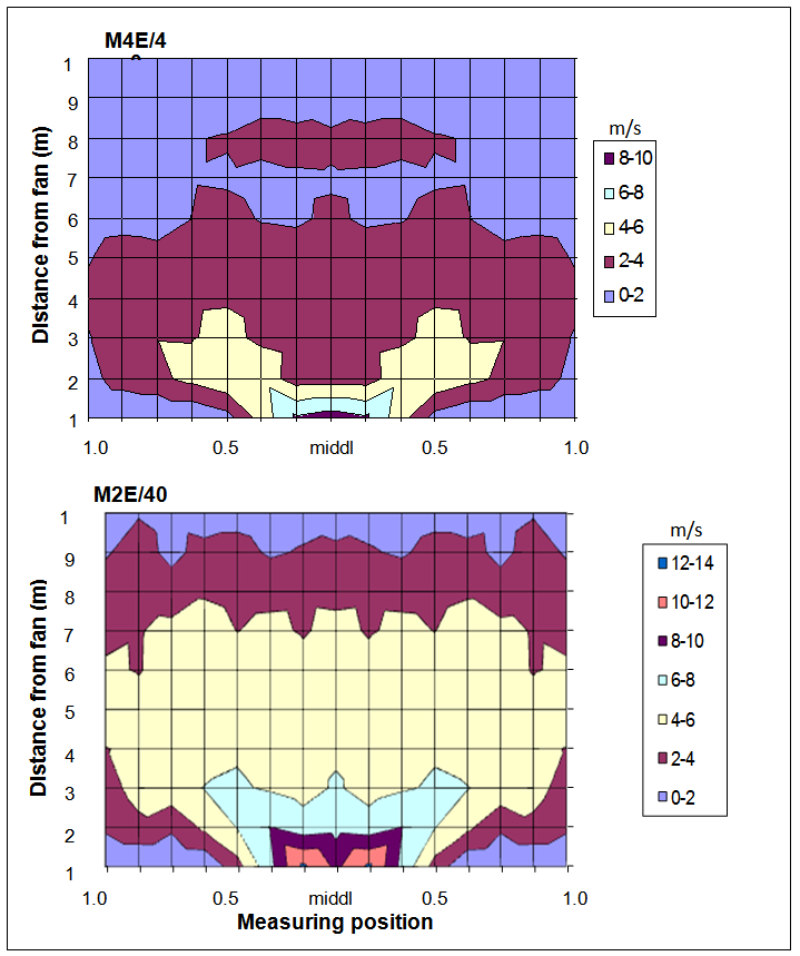 | Figure 1. Air velocity profile (m/s) at 0.15 m height for M4E/40 and M2E/40 mixing fans located at floor region |
3.1.2. Fans Located at 1.5 m Height
3.1.2.1. 60° Tilt Angle
- The air velocities in blowing direction of M4E/40 and M2E/40 fans located at 1.5 m height were measured at 0.15 m height at different measuring locations namely; at the middle, 0.5 m and 1 m. Figure 2 showed that in front of the fan, the air velocity ranged from 0 to 1 m/s until the 3rd m for M4E/40. From the 4th m until the 9th m, the air velocity has increased from 1 to 3 m/s and then decreased again at the 10th m. Maximum air velocities of 2-3 m/s at the 4th and 5th m were distributed from the middle to 0.5 m. For M2E/40, a maximum air velocity of 3-4 m/s was recorded (Fig. 2). At 0.5 m measuring location, the air velocity was 2-3 m/s at the 5th-7th m, and thereafter the air velocity decreased with increasing the distance until it reached 1-2 m/s at the 8th m and 0-1 m/s at the 10th m. The same trend was observed for 1 m measuring location. The air velocity produced by M2E/40 was significantly the same as for M4E/40 with a mean of 0.98 m/s vs. 1.11 m/s, respectively (F=0.659; P<0.05). Overall, in all measuring locations the air velocity produced by fans was significantly the highest in the distance ranged from 5th until 7th m for both M2E/40 (F=17.91; P<0.05) and M4E/40 fans (F=48.32; P<0.05).
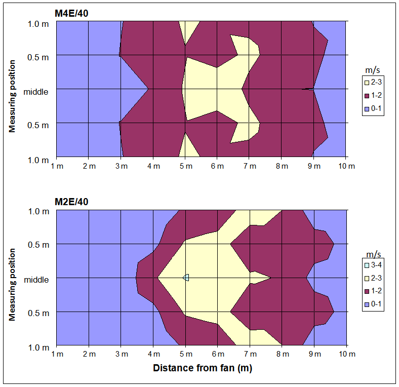 | Figure 2. Air velocity profile (m/s) at 0.15 m height for M4E/40 and M2E/40 mixing fans located at 1.5 m height above the floor region with 60° tilt angle |
3.1.2.2. 55° Tilt Angle
- The results demonstrated that air velocity for M4E/40 fan at the middle location was 0-1 m/s for the first two meters (Fig. 3). Thereafter, it increased with increasing the distance, where the maximum air velocity was 3-4 m/s at the 3rd-6th m. At measuring locations of 0.5 m and 1 m, the air velocity was 1-2 m/s at the 3rd-4th m, and then it valued only 0-1 m/s until the 10th m. For M2E/40, the velocity at the middle was 0-1 m/s for the first three meters (Fig. 3). Maximum air velocity of 3-4 m/s was recorded at the 5th m, and then it started to decrease until it reached 0-1 m/s at the 10th m. The same trend of results was recorded for 0.5 m and 1 m measuring locations. The air velocity produced by M2E/40 was significantly greater than M4E/40 with a mean of 1.09 m/s vs. 0.58 m/s, respectively (F=3.358; P<0.05). Overall, in all measuring locations the highest air velocity was significantly produced by M2E/40 (F=34.29; P<0.05) in the distance ranged from 5th to 8th m, while for M2E/40, the highest air velocity was significantly obtained at 3rd to 5th m (F=1.79; P<0.05). By comparing 60° and 55° tilt angles, the results revealed that at 60° for M4E/40 the air velocity profiles distributed widely than that of the same fan at 55°, where the air velocity distributed until 1 m measuring location for 60°, and only to 0.5 m measuring location for 55° as seen in figures 2 and 3. For M2E/40, the results showed that there is no big variation in the distributed air velocity between 60° and 55° tilt angles as shown in figures 2 and 3, where the maximum air velocities were 3-4 m/s at the 5th m. The statistical analysis indicated that there were no significant differences between 60° and 55° tilt angles for M2E/40 fan (F=0.139; P=0.719), while the air velocity produced at 60° was significantly greater than 55° for M4E/40 fan with a mean of 1.11 m/s vs. 0.58 m/s, respectively (F=5.386; P<0.05).
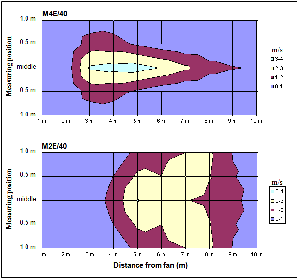 | Figure 3. Air velocity profile (m/s) at 0.15 m height for M4E/40 and M2E/40 mixing fans located at 1.5 m height above the floor region with 55° tilt angle |
3.2. Ceiling Fans
- PV60 ceiling fan placed at 3.8 m and PV36 ceiling fan located at 3.2 m (Fig. 4) above the floor level were tested at 1 m height from the floor region. The air velocities were being integrated to include all the air entrained at the tested plane. The results revealed that at the middle location, the air velocity was 2.19 m/s and 1.33 m/s for PV36 and PV60, respectively. The air velocity started to decrease while moving away from the middle location until it reached 0 m/s at 0.8 m measuring location for PV36. For PV60, the air velocity began to rise until reached 2.4 m/s at 0.3 m measuring location, and then it decreased to 0 m/s at 1 m. The air velocity produced by PV60 was 1.5-fold greater than PV36, but there were no significant differences between the two fans (F=0.246; P=0.184).
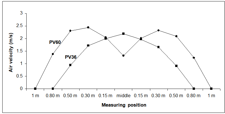 | Figure 4. Air velocity profile (m/s) for PV36 and PV60 ceiling fans at 1 m height above the floor region |
4. Discussion
- Air velocity is one of the main environmental factors involved in thermoregulation, especially when outdoor temperature and relative humidity are high and the efficiency of the evaporative cooling systems is limited. However, increasing the rate of air movement over the birds is necessary to protect them against high temperature [21]. Agricultural fans can play an important role in ventilating poultry houses and reducing the side effect of heat stress. Additionally, type, placement location and tilt angle of the fan influence air velocity in the bird’s area. The current results showed clearly that when the fans (M4E/40 and M2E/40) located at the floor region the air velocity distributed along 10 meters. Also, the point of maximum air velocity moves downward with increasing the distance from fan location. The air velocity was declined when moving from the middle location toward the other measuring locations (0.15, 0.3, 0.5, 0.6, 0.7, 0.8 and 1 m) for both fans tested. In a similar fashion, Bottcher et al. [22] reported that air velocities increase along the centreline from 3 to 9 m from the fan and then declined with distance. While according to Bottcher et al. [23], the air velocities increased from 0.5 to 1 m/s directly below the center of the fan, and reached its maximum (1.5-2.0 m/s) at the 3rd m from the center, and then slowly decreased to 0.5-0.9 m/s at the 8th m from the fan center. These results of Bottcher et al. [22, 23] are in agreement with the present results, where the air velocity increased significantly and then decreased with increasing the distance from the fan. In addition, the current results showed that M4E/40 generates significantly air velocities less than M2E/40, where the maximum air velocity resulted from M2E/40 fan was 15 m/s as compared to only 10 m/s for M4E/40 fan. This indicates that M4E/40 might cause fewer disturbances for the birds than M2E/40. These results are in agreement with a conclusion made by Bottcher et al. [24], where high air velocities disturb the birds. Additionally, Bottcher et al. [24] mentioned that it may be possible to effectively cool birds with maximum velocities above 2 m/s. This is in line with the current results when the fans located at the floor region, where the air velocities close to fan were more than 2 m/s for both mixing fans. According to Yahav et al. [12], an air velocity of 1.5-2 m/s is the optimal to achieve an optimal birds' performance under very hot conditions (< 35°C). In this study, for example, at 0.15 m height when fans located at the floor region for M4E/40, an air velocity of 2 m/s was obtained from the 6th to 10th m. For M2E/40, an air velocity of 2 m/s was recorded for the whole 10 meters starting from 0.5 to 1 m measuring locations. During acute exposure to high temperature of 30°C, an air movement in the range of 0.30 to 1.05 m/s may be employed as an effective form of cooling, decreases the demand for evaporative heat loss and reduces body temperature [25]. Further studies pointed out that air velocity up to 1 m/s seems to have a beneficial effect on young chicks [26]. Furthermore, even air velocities as high as 2.5-3.0 m/s help chickens to tolerate increasing temperature up to at least 40°C [27]. Therefore, apparently it can be managed by locating birds at a certain distance from the fans to achieve the optimal performance.Modifying mixing fan tilt angle to increase air velocity at bird level has the potential to prevent heat stress effect on birds' performance without necessarily resulting in an excessive bird migration toward the fans [28]. The present results demonstrated that when the fans (M4E/40 and M2E/40) located at a height of 1.5 m at 60° tilt angle, air velocity in front of the fan was increased and then decreased again for both fans. Maximum air velocities of 2-3 m/s for M4E/40 and 3-4 m/s for M2E/40 were recorded. The same trend was observed for measuring locations of 0.5 and 1 m. Therefore, in general the maximum air velocity generates by M2E/40 was greater than M4E/40 as noticed when the same fans located at floor region. At 55° tilt angle, the results showed that air velocity at the middle was 0-1 m/s in the 1st m for M4E/40 and in the first four meters for M2E/40. Thereafter, it increased with distance, where the maximum velocity was 3-4 m/s for both fans. In this regard, Bottcher et al. [22] reported that air velocities are found to decrease with increasing the horizontal distance from the fan, fan produced air velocities at bird level of 3.4, 2.5 and 2 m/s at distances of 1.8, 3 and 4 m from the fan, respectively. In general, this observation is agreed with all measuring locations for 55° and 60° tilt angles of the current study. Furthermore, our results revealed that by comparing tilt angles of 60° and 55° for M4E/40, air velocity profiles were widely distributed at 60° than 55°, where the air velocity distributed to 1 m measuring location for 60° and only to 0.5 m measuring location for 55°. Furthermore, for M2E/40, the results showed that there were no significant differences in the air velocity distribution between the two angles, while the air velocity produced at 60° was significantly greater than 55° for M4E/40 fan with means of 1.11 m/s vs. 0.58 m/s, respectively. The results of the present study for fan located at 1.5 m have similar trend with the results of Bottcher et al. [24], who reported that for tilt angles below 20°, the area averaged velocity increases with tilt angle and decreases with increasing fan height; at higher tilt angle the area-averaged velocity raised very little with fan height, at tilt angle below 10° the maximum velocities for two lower measurement heights of 0.41 and 0.1 m differ only slightly. As mentioned before, Bottcher et al. [24] and Yahav et al. [12] found that an air velocity of 2-3 m/s and 1.5-2 m/s, respectively, is the optimal for birds. This range of air velocity was found at different fan heights and measuring locations at the bird’s level. For example, when fans located at 1.5 m at 60° tilt angle, air velocities of 2-3 m/s at bird’s area were reported from the 2nd to 6th m from the middle to 1 m measuring location. While for M2E/40, 2-3 m/s air velocity was observed from the 5th to 7th m from the middle to 1 m measuring location.The results of the current study on PV60 and PV36 ceiling fans (placed at 3.8 m and 3.2 m above the floor level, respectively) showed that the air velocities tested at 1 m height from the floor region are being integrated to include whole air entrained at the tested plane. At the middle location, the air velocity was 1.33 m/s and 2.19 m/s for PV60 and PV36, respectively. Thereafter, the air velocity started to decrease while moving away from the middle location for PV36. For PV60 the air velocity began to rise, and then it decreased again. The present results agreed with Gavaret [30], who stated that the air velocity decreases when distance from the centre increases. Furthermore, he mentioned that at the maximum fan speed, the air velocity near the floor reaches a peak of 2.2 m/s, and air movement can be measured out to a distance of 5.5 m from a point on the floor directly under the centre of the fan. The air is supposed to move with air velocity at a level of approximately 2 m/s through all the length of a building, thus cooling the birds by convection [31]. Gavaret [30] reported that ceiling fans are well suited for air circulation in poultry houses because they are simple and inexpensive way to create air circulation where birds are located at a height of 45 cm. According to Daly [28], ceiling fans might be seated with the head directly in the air stream. Ernst [32] indicated that vertical ceiling fans are used to cool chickens locating them about 3.7 m above the birds.One of the most serious problems associated with using ventilation fans is the migration of broilers toward the high air velocity. Therefore, the effect of air velocity in poultry houses on the migration of birds should be taken into account, when determining the performance of a certain fan. Consequently, birds 'crowding reduces performance due to increased heat stress as they considered as heat source. Runge [29] suggested that air speed over heat stressed birds should be limited to avoid excessive birds' migration into areas of high air speed. Kuczynski [31] reported that such a profile of air velocities from 0.5 to 2 m/s encourages broilers to move looking for the thermal conditions, which would best suit their needs. In addition, the tilt angle in which the fan is directed can play an important and significant role in air distribution and birds' migration. Also, migration fences are a key point to maintain birds' uniformity down the length of the house without causing dead air spots.In conclusion, it is clear that mixing and ceiling fans used in the current study are feasible to be used for poultry barns to reduce heat stress. The air velocity produced by M2E/40 was significantly greater than M4E/40, and at 60° tilt angle than at 55°. Overall, in all measuring locations the air velocity produced by fans was significantly low, and then increased, and hereafter decreased until the 10th m for both fans. When choosing a fan, there are some important criteria should be taken into account, i.e. quantity of air delivered at different static pressures, energy efficiency, quality of dealer service and support, reliability and life, sustainability and costs [18]. Selection of fan location and number of fans/barn are very important points to be taken into account to obtain the best air distribution and to avoid the expecting problems that can be faced by labour inside poultry houses. Thus, further studies are required to test the effect of the combination of different types of fans inside poultry houses, number of fans/barn, and to examine if these fans are appropriate for poultry houses located at very hot and dry nature regions.