-
Paper Information
- Next Paper
- Previous Paper
- Paper Submission
-
Journal Information
- About This Journal
- Editorial Board
- Current Issue
- Archive
- Author Guidelines
- Contact Us
International Journal of Agriculture and Forestry
p-ISSN: 2165-882X e-ISSN: 2165-8846
2012; 2(4): 166-170
doi: 10.5923/j.ijaf.20120204.06
Numerical Evaluation of Longitudinal Modulus of Elasticity of Eucalyptus grandis Timber Beams
 Abstract
 Reference
 Full-Text PDF
 Full-Text HTML
André Luis Christoforo 1, Francisco Antonio Rocco Lahr 2, Elen Aparecida Martines Morales 3, Túlio Hallak Panzera 1, Paulo Henrique Ribeiro Borges 4
1Department of Mechanical Engineering, Federal University of São João del-Rei, São João del-Rei, 36307-352, Brazil
2Department of Structural Engineering, University of São Paulo, São Carlos, 13566-590, Brazil
3Department of Wood Engineering, São Paulo State University, Experimental Campus of Itapeva, Itapeva, 18409-010, Brazil
4Department of Civil Engineering, Federal Center of Technological Education of Minas Gerais, Belo Horizonte, 30510-000, Brazil
Correspondence to: André Luis Christoforo , Department of Mechanical Engineering, Federal University of São João del-Rei, São João del-Rei, 36307-352, Brazil.
| Email: |  |
Copyright © 2012 Scientific & Academic Publishing. All Rights Reserved.
Currently, the standard NBR 7190:1997 (Design of Wood Structures) makes no reference to any test aimed to determine the stiffness and strength of structural-sized lumber components, restricting this analysis to small and clear specimens. Methodologies proposed by international standard do not include optimum criteria in their calculation models. This study presents an alternative methodology to determine the longitudinal modulus of elasticity in Eucalyptus grandis timber beams, based on a combination between the Finite Element and the Least Square Methods. Besides the use of numerical methods, the modulus of elasticity was also analytically obtained by the equation presented in NBR 7190:1997, concerning the static three-point bending test, adapted to a non-destructive testing condition. Results found for the elastic modulus for the Eucalyptus grandis species showed statistical equivalence between the methodologies, which implies the reliability of using Brazilian standard for the characterization of structural components subjected to bending. However, these results cannot be extended for other woods from the same species or different species, justifying the use of the numerical calculation approach discussed in this paper.
Keywords: Modulus of Elasticity, Lumber, Finite Element Method, Least Square Method, Bending Beams
1. Introduction
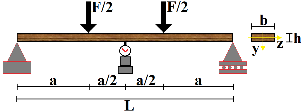
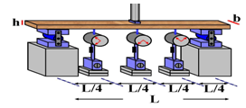
- Wood has been widely used to build structures because it is a renewable material with an excellent strength-to-density ratio in compare to steel[1].Design of timber structures, as well as of other materials, requires the knowledge of some variables, including the modulus of elasticity, obtained through experimental tests recommended by standard documents, which can be destructive or not.Being wood orthotropic and heterogeneous, experiments aimed at characterizing this material, by evaluating its bending behaviour, must be held on structural-sized components in order to improve their reliability. In this context, only international standards can be mentioned, since the Brazilian standard[2], which deals with wood characterization, only includes destructive testing conditions using small and clear specimens.American standard[3] recommends the static four-point bending test (Figure 1) to determine the bending modulus of elasticity (Em), expressed by the Equation 1, being F the applied force, provided that the limit of proportionality is not exceeded, L the span between supports, a the distance between the applied forces, b the specimen width, h the specimen thickness and δ the deflection at the middle of the span.
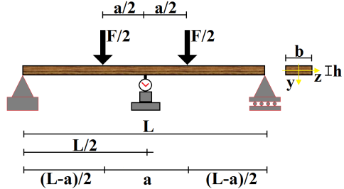 | Figure 1. Static four-points bending tests[3] |
 | (1) |
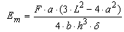
 | Figure 2. Four-point static bending[4] |
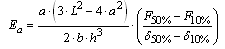 | (2) |
 | Figure 3. Static three-point bending tests[5] |
 | (3) |
 | (4) |
2. Materials and Methods
- To determine the modulus of elasticity, 20 Eucalyptus Grandis elements with dimensions of 6cm16cm200cm were used, respecting the
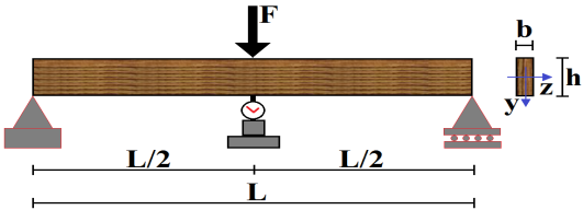
 ratio and neglecting the influence of shear force on the deflection calculus[8].Experiments held to determine the modulus of elasticity are considered as non-destructive tests, because the highest displacement value found is limited to the L/200 ratio, where L is the span between supports, expressed in centimeters. This is an average of small displacements defined by standard (NBR 7190 )[2], which implies physical and geometrical linearity for the timber beams.In this paper, the modulus of elasticity is evaluated according to two distinct mathematical calculation models, both making use of the static three-point bending structural scheme. In the first, adapted from[2], the modulus of elasticity (Eeq) is determined by the Equation 5, where F* is the force responsible for causing a displacement equal to L/200, and b and h are the basis and height measurements of the pieces cross-section. In the second, as an alternative way of calculation, it is proposed that the value of the effective modulus of elasticity (Eef) be determined according to the structural testing scheme shown in Figure 4.
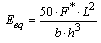 | (5) |
 | Figure 4. Alternative test to determine the effective modulus of elasticity |
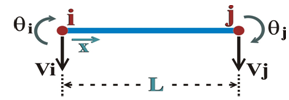 | Figure 5. Finite-element degrees of freedom |
 | (6) |
 | (7) |
3. Results and Conclusions
- The Elasticity values Eeq and Eef found for the Eucalyptus grandis components are shown in Table 1.
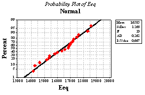 | Figure 6. Normal probability plot for the modulus of elasticity Eeq |
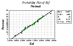 | Figure 7. Normal probability plot for the modulus of elasticity Eef |
 and, since zero belongs to the interval, they are proven to be statistically equivalent. The confidence interval of the modulus of elasticity responses is shown in Figure 8.
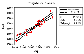 | Figure 8. Confidence interval plot for Eeq and Eef responses |
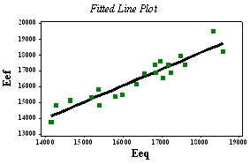 | Figure 9. Linear regression between Eeq and Eef |
 was able to use the Bernoulli Beam Theory in both methodologies which considered no shear effects in the calculus of displacements[8].Statistical equivalence between the elasticity values Eeq and Eef point to the fact that the methodology recommended by Brazilian standard[2] was also proven to be efficient for Eucalyptus grandis structural-sized timber components. However, these results may not apply to wood components and/or species other than the ones herein evaluated. It is worthy of note that the presented methodology can also be used to characterize specimens, and not only lumber, but also glued-laminated timber beams, wood panels and others.
References
| [1] | C. Calil Jr., F. A. R. Lahr, A. A. Dias, "Dimensionamento de elementos estruturais de madeira", Editora Manole Ltda, Barueri – SP, ISBN: 85-204-1515-6, 2003. |
| [2] | Associação Brasileira de Normas Técnicas (ABNT), "Projeto de Estruturas de Madeira", NBR 7190, Rio de Janeiro, 1997. |
| [3] | American Society for Testing and Materials (ASTM), "Standard test method of static tests of lumber in structural sizes", ASTM D 198, Annual book of ASTM standards, v. 03.01. ASTM, West Conshohocken, Philadelphia, 1997. |
| [4] | American Society for Testing and Materials (ASTM), "Standard methods of testing structural panels in flexure", ASTM D 3043-95. Annual book of ASTM standards, ASTM, West Conshohocken, Philadelphia, 1995. |
| [5] | American Society for Testing and Materials (ASTM), "Standard test methods for mechanical properties of lumber and wood-base structural material", ASTM D 4761-96, Annual book of ASTM standards, ASTM, West Conshohocken, Philadelphia, 1996. |
| [6] | D. Guitard, "Mécanique du matériau bois et composites", Cepadues-editions, France, 1987. |
| [7] | J. Bodig, B. A. Jayne, "Mechanics of wood and wood composites", Krieger Publishing Company, Malabar, Florida, 1992. |
| [8] | F. A. Rocco Lahr, "Sobre a determinação de propriedades de elasticidade da madeira", Tese de Doutorado, Escola de Engenharia de São Carlos, Universidade de São Paulo, São Carlos, SP, 216p, 1983. |
| [9] | European Standard (EN), "Estruturas de Madeira - Métodos de teste - Determinação das propriedades mecânicas de painéis derivados de madeira", EN 789, European Stardard (versão portuguesa), Bruxelas, 1995. |
| [10] | American Society for Testing and Materials (ASTM), "Standard specification for evaluation of structural composites lumber products", ASTM D 5456, Annual book of ASTM standards, ASTM, West Conshohocken, PA, 2006. |
| [11] | H. A. L. Palma, A. W Ballarin, R. M. Abilio, "Propriedades mecânicas de painéis LVL de Pinus tropicais", In: XI Encontro brasileiro em madeira e estruturas de madeiras, Londrina, 2008. |
| [12] | H. A. L. Palma., A. W. Ballarin, C. D. Rocha, "Propriedades de flexão de vigas LVL de Eucalyptus grandis", In: XI Encontro brasileiro em madeira e estruturas de madeiras, Londrina, 2008. |
| [13] | J. C. Pigozzo, E. Pletz, F. A. R. Lahr, "Aspectos da classificação mecânica de peças estruturais de madeira". In: VII Encontro Brasileiro em Madeiras e em Estruturas de Madeira, São Carlos, SP, 2000. |
| [14] | J. Fiorelli, "Estudo teórico e experimental de vigas de madeira laminada colada reforçadas com fibra de vidro", São Carlos: USP, 2005. 108p. Tese (Doutorado em Ciência e Engenharia de Materiais) - Universidade de São Paulo, 2005. |
| [15] | J. L. Miotto, A. A. Dias, "Produção e avaliação de vigas de madeira laminada colada confeccionadas com lâminas de eucalipto". Revista Tecnológica, Edição Especial ENTECA, p. 35-45, 2009. |
| [16] | R. J. Ross, B. K. Brashaw, R. F. Pellerin, "Nondestructive evaluation of wood", Forest Products Journal, v. 48, n. 1, p. 14-19, 1998. |
| [17] | A. J. S. Miná, F. G. R. Oliveira, C. Calil Jr, A. A. Dias, A. Sales, "Avaliação não destrutiva de postes de madeira por meio de ultra-som", Scientia Forestalis, n. 65, p. 188-196, 2004. |
| [18] | X. Wang, R. J. Ross, B. K. Brashaw, J. Punches, J. R. Erickson, J. W. Forsman, R. Pellerin, "Diameter effect on stress-wave evaluation of modulus of elasticity of logs". Wood and Fiber Science, v. 36, n. 3, p. 368-377, 2004. |
| [19] | R. Wolfe, J. Murphy, "Strength of small-diameter round and tapered bending members". Forest Products Journal, v. 55, n. 3, p. 50-55, 2005. |
| [20] | S. Y. Wang, J. H. Chen, M. J. Tsai, C. J. Lin, T. H. Yang, "Grading of softwood lumber using non-destructive techniques". Journal of Materials Processing Technology, v. 208, p. 149-158, 2008. |
| [21] | J. Xiao, C. Sa., Y. Han, "Nondestructive Testing of Dynamic Elastic Modulus of Wood-Basedpanel by the Method of Stress Wave". Proceedings of the 9th International Conference on Electronic Measurement and Instruments ICEMI, Vol.2, Beijing, China, pp. 357-361, 2009. |
| [22] | M. Yamasaki, Y. Sasaki, "Determining Young’s modulus of timber on the basis of a strength database and stress wave propagation velocity I: an estimation method for Young’s modulus employing Monte Carlo simulation". Journal of Wood Science, v. 56, n. 4, p. 269-275, 2010. |
| [23] | A. Sales, M. Candian, V. S. Cardin, "Evaluation of the mechanical properties of Brazilian lumber ( Goupia glabra) by nondestructive techniques". Construction and Building Materials, v. 25, n. 3, p. 1450-1454, 2011. |
| [24] | F. G. R. Oliveira, A. Sales, "Ultrassonic measurements in Brazilian hardwood", Materials and Research, v. 5, n. 1, p. 51-55, 2002. |
| [25] | M. C. C. Werkema, S. Aguiar, "Planejamento e análise de experimentos: como identificar e avaliar as principais variáveis influentes em um processo", Belo Horizonte, Fundação Christiano Ottoni, Escola de Engenharia da Universidade Federal de Minas Gerais, 1996. |