Koji Murai 1, Yuji Hayashi 1, Tsunemasa Saiki 2, Kohei Higuchi 3, Takayuki Fujita 4, Kazusuke Maenaka 4
1Maritime Sciences, Kobe University, Kobe, 658-0022, Japan
2Ecological and Biological Technology, Hyogo Prefectural Institute of Technology, Kobe, 654-0037, Japan
3Exploratory Research for Advanced Technology, Japan Science and Technology Agency, Himeji, 671-2280, Japan
4Electrical Engineering and Computer Sciences, University of Hyogo, Himeji, 671-2280, Japan
Correspondence to: Koji Murai , Maritime Sciences, Kobe University, Kobe, 658-0022, Japan.
| Email: |  |
Copyright © 2012 Scientific & Academic Publishing. All Rights Reserved.
Abstract
A pilotage is one of important factors in order to keep a safety and a security of main harbors in Japan; however, pilots’ marine accidents sometime happen while they work. The pilots’ accidents happen for the transfer from vessel to pilot boat on the sea, and pilots and pilots’ associations do their best for reducing the accidents under International Maritime Organization (IMO) convention. In other word, a safety measure for the transfer is the important subject for pilots.The purpose of this paper is to evaluate a pilot’s physical performance while their work using large model sensors (smallacceleration sensors) to prevent a fall accidentwhen they transfer from the vessel to the pilot boat, and we read characteristics of performance for the transfer. This research is first challenge to evaluate the pilots’ performance in real situation.
Keywords:
Sea Pilot, FallAccident,Accelerationof Body,SafePilot Transfer, Large Model Sensor
Cite this paper:
Koji Murai , Yuji Hayashi , Tsunemasa Saiki , Kohei Higuchi , Takayuki Fujita , Kazusuke Maenaka , "Evaluation of A Sea Pilot Candidate’s Performance Using Small Acceleration Sensor", Human Resource Management Research, Vol. 2 No. 4, 2012, pp. 59-64. doi: 10.5923/j.hrmr.20120204.04.
1. Introduction
A sea pilot (pilot)[1],[2] is one of important economic supporter who guide a huge vessel safely in a bay worldwide. The vessel is one of factorsof human resource management in a port of the maritime field, because the all maritime business comes together at the port-the warehouse, transportation, port authority (government), and etc., and the pilot is key person to connect among them. Moreover, they hold the responsibility of huge products and energy in main cities. There are 35 associations, and 5 (Tokyo, Ise-Mikawa, Osaka, Naikai and Kanmon) is main area in Japan[3]. They, in pilotage, have to take a vessel on the sea. In a detail, theytransfer from pilot boat to vessel and from vessel to pilot boat on the sea using the ladder, and this situation is most dangerous for physical performance while their works. Becausetheymay fall in the sea when transfervessel to pilot boat. A pilot’s marine accident report shows an average death rate at the transfer is every three years[4], and the research on pilots’marine accident conduct in Japan[5]-[8]. More safe transferto the vessel on the sea is the importantsubject for them. The research on pilot’s maritime accident does not clear yet, and we started to tackle this research from 2007.* Corresponding author:Koji MuraiMeanwhile the Japanese pilot low revised at 2006[9]. The license had three grades from first to third; the first gradeisstandard, they need the captain’s on-board experience, and the third grade is new. The first grade needs captain’s experience, but the others do not.The education is carried out at two maritime universities, master’s degree course of graduate school, Kobe University and Tokyo University of Marine Science and Technology, and one marine technical college for 2.5 years till the state pilot examination. We tackle to find the best measures for takingand leaving the vessel on the sea.At first, we need to clear their performance[10],[11] and mental workload[12]-[14] on a real pilotage. In this paper, we aim the measurement of the performanceusing body acceleration. This paper shows characteristics of the performance for on-board and leaving/taking the vessel.
2. How to Transfer to Vessel and Pilot Boat on the Sea
There are two cases- entering a port, and going to an open sea, for taking and leaving the vessel they guide. On entering the port, the pilot moves to the embarkation position using a pilot boat where was determined for each sea areas, and take the vessel using pilot ladder the vessel readies. The pilot ladder is defined worldwide by International Maritime Organization (IMO) convention[15]-[17]. They leave the vessel using an accommodation ladder at the port. On the other hand, they have inverse process for leaving the port- they take the vessel at the berth, guides to entrance of the bay, leaving the vessel on the sea, and transfer to the pilot boat.Figure 1 is an image of leaving the vessel on the sea[3].The pilot ladder consists of ladder-steps and man-ropes. Especially, Ise-Mikawa bay regards the man-ropes. This paper chose Osaka bay and Ise-Mikawa bay as the experimental place.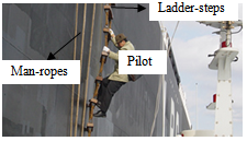 | Figure 1. Transfer to the vessel/pilot boat on the sea[3] |
2.1. Osaka Bay
In Osaka bay, the position of dis/embarkation is at Tomoga-shima off. In details, the embarkation position is 7 nautical miles (mile) south from Tomoga-shima light house, and the disembarkation position is 3 miles south from coast end of Awaji-Shima (black circles in Figure 2).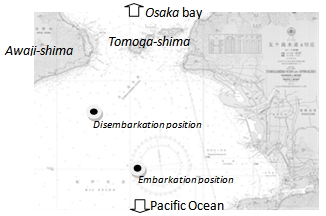 | Figure 2. Dis/Embarkation position in Osaka bay |
The dis/embarkation positions have differentcharacteristics-Disembarkation position: Awaji-shima protects north wind. In case of south swell, the vessel set the pilot ladder starboard side and ships head go to west for keeping lee side. Mostly, the course is 220 to 240 degrees. Sometime, in case of west wind, sets the ladder port side and the ship course 180 degrees.Embarkation position: the ship course is 000 (North) to 030 degrees, and the set of pilot ladder depends on wind direction.
2.2.Ise-Mikawa Bay
The pilot serves 3 kinds of pilotage in Ise-Mikawa bay- “Bay”, “Harbour”, and “Shift” work. “Bay” is navigation (Fig.3: B), “Harbour” is entering/leaving port (Fig.3: C), and “Shift” is change to other berth (Fig.3: A). We name both of “Bay” and “Harbour”“Through” work. The black circle of Figure 3 shows dis/embarkation position.In this paper, we target the situation of leaving vessel for reason why the remarkable accidents occurs at transfer from vessel to pilot boat on the sea[4].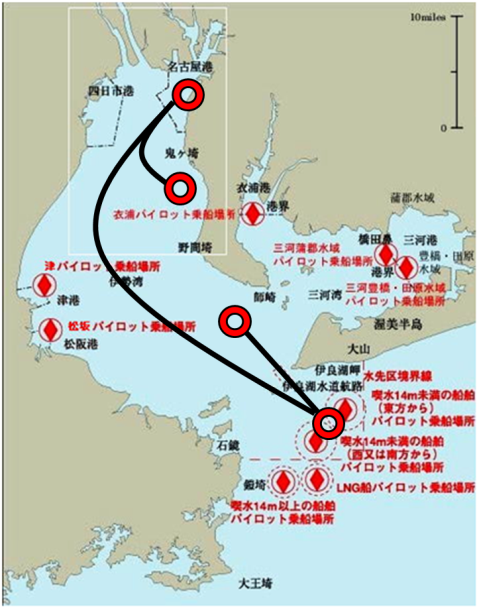 | Figure 3. Dis/Embarkation position in Ise-Mikawa bay (Black circle) |
3. Experiment
We carried out two kinds of experiment. One is on-board experiment included a daily life for evaluating general performance before the pilot’s performance evaluation. The other is dis/embarkation experiment for evaluating pilot’s performance. We need the pre-experiment to understand how to set sensor on the body, and sensor and human on-board characteristics to evaluate the pilot performance.
3.1. On-board experiment (Pre-experiment)
First, we confirm the on-board performance- navigational watch, on-board general life, and the daily life in a school.The experiment was carried out using Training Ship Fukae-maru of Kobe University, Graduate School of Maritime Sciences (Figure 4). Her length is 49.95 meters, width is 10.00 meters, draft is 3.20 meters, and tonnage is 449.0 tons.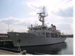 | Figure 4. T.S. Fukae-maru of Kobe University, Graduate school of Maritime Sciences |
Figure 5 is on-board experimental sea area on the west side of Japan. The experiments are 9 kinds of navigational situations- two entering/leaving ports (1. Fukae, 2. Moji), two anchorages (3. Ube, 4. Usuki-wan), two night-navigations (5. Inland sea, 6. off Tosa), and three narrow passages (7. Akashi, 8. Kurushima, 9. Kanmon).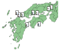 | Figure 5. The experimental sea area on west side of Japan |
The subjects are cadets (male, 22-23 age of year), has an officer (navigation) license, of deck part of Maritime Sciences, Kobe University. A tester measures their body accelerations using large model acceleration sensor (Proto-type II) (Figure 6), and records the experimental situations and conversations using IC recorder.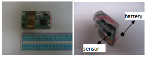 | Figure 6. Proto-type II Acceleration sensor |
The sensor Proto-type II (acceleration: MMA7331L[18]) is W:50×H:30×D:11 (sensor base 5[mm] + battery 6[mm])[mm3], range (-) 4 to (+) 4[G] (LSB 8[mG]), data sampling time 16[sec]. The senor and battery part combined (Figure 6). We are able to select two range modes (+)/(-) 4 and (+)/(-) 12[G], and selected 4[G] is enough for the daily life.This size is good not to make the measurement load of the body; the subjects dislike carrying unnecessary goods for their works. Especially, they take care while taking and leaving the vessel on the sea. In other words, the sensor should not increase their physical workload.The following condition is minimum requirements for the sensor.•SizeSmall: sensor does not give an extra physical workload for subjects.•WeightLight: 10[g] include battery.•OperationUnnecessary: only push start button before the experiment.•Record24 hours over: sensor has a memory.•Power sourceBattery: memory is able to record over 24 hours.The sensor fixed on a belt at the waist. The relationship between sensor acceleration axes and body is shown in Figure 7.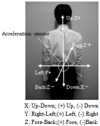 | Figure 7. Relationship between sensor axes and body |
The body gravity center is stable and the most suitable for measuring the body performance.We show results of on-board experiment (Figure 8(b)); moreover, results of daily school life also in Figure 8(a) using the same sensor, Proto-type II. In Figure 8, X- red line is fore-back, Y- green line right-left, Z- blue line up-down of the body. The numbers ‘1’ to ‘7’ show points of going up and down stairs in both Figures. The arrow means going down ‘↓’ and up ‘↑’ each. Figure 8 shows the raw data, and z axis (up- down) is approximately ‘1’ or ‘(-)1’ for the gravity.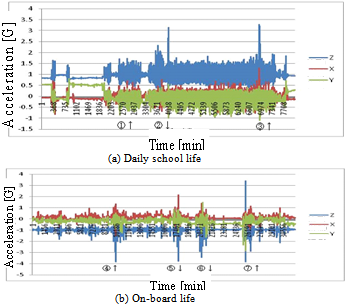 | Figure 8. The results of cadet’s body accelerations |
From Figure 8, the remarkablebody acceleration appeared for going down and up stair at points of the arrow, and the value is 3[G], is a maximum, during the experiments. Moreover, the values are larger than the school life. We estimate the reason depends on the stairs angle. The angle of stair in theship is steeply compared with school one. The ship is 45 degrees and school 30 degrees. Also going up and down occurs often in the ship.We are able to confirm the remarkable body acceleration of on-board life is 3[G], and the body is active for toward Z up-down and Y right-left from the fluctuations. We need to fit the mathematical formula for the measured feature in a future research.
3.2. Dis/Embarkation Experiment
The dis/embarkation experiment was carried out at Osakaand Ise-Mikawabay for 3 and 1 pilot candidates (male, 23-32 age of year) each. The measured data is total 21 cases- embarkation 12 and disembarkation 9 (Table 1) in Osaka, and total 11 cases- embarkation 6 and disembarkation 5 (Table 2) in Ise-Mikawa.| Table 1. Subjects and Number of Measured Data (Osaka bay) |
| | Subject | Data Number | | Disembarkation | Embarkation | Total | | A | 5 | 6 | 11 | | B | 3 | 3 | 6 | | C | 1 | 3 | 4 | | Total | 9 | 12 | 21 |
|
|
| Table 2. Subjects and Number of Measured Data (Ise-Mikawa bay) |
| | Subject | Data Number | | Disembarkation | Embarkation | Total | | D | 5 | 6 | 11 |
|
|
Subjects wear 3 axes large model acceleration sensor (Proto-type I) at the waist where is similarto body gravity center (Figure 8). This was confirmed by on-board experiments.The Proto-type I (acceleration: MMA7261QT-ND) is W:54×H:39×D:18[mm3], range (-) 10 to (+) 10[G] (LSB 0.04[G]), data sampling time 1[sec], and measure minimum and maximum value for 3 axes every second. The sensor and battery part set in the plastic case (Figure 9).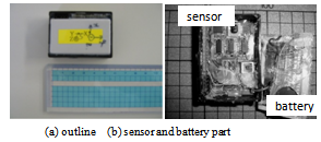 | Figure 9. Proto-type I Acceleration sensor |
Here, though the on-board experiment was Type II, we used deferent sensor, Proto-type I. Because we, in dis/embarkation experiment, need a large memory to record the performance over 24 hours continuously. The Proto-type II did not satisfy the over 24 hours.
4. Results
4.1. Osaka bay
Table 3,one of typical results, shows maximum and minimum values for the experiments, the measured time from berth to disembarkation position was total 3.5 hours.The guided ship is Bulk Carrier, 17,977 gross tonnages, wind direction and speed NNW, 3-4[m/s] average at the disembarkation position, pilot ladder set at starboard, and ship course and speed 220 degrees, 8 knots.| Table 3. Maximum and Minimum values of Acceleration in Pilotage (Subject B) |
| | | X: U-D | Y: R-L | Z: F-B | | Max.[G] | 3.20 | 3.59 | 2.53 | | Min.[G] | -1.77 | -1.97 | -2.90 |
|
|
From Table 3, more than 3[G] appeared toward up-down and right-left of the body, 3.20[G] and 3.59[G] each. The values of transferred from vessel to pilot boat is larger than the embarkation.We show the results of measured 3 axes minimum and maximumevery second for leaving vessel in Figure10. In Figure 10, ‘A’ to ‘E’ is events for subject performance for transferring from vessel to pilot boat.From Figure 10;X[up-down]: the remarkable acceleration appeared while moving from the deck of vessel to pilot ladder and from vessel to pilot boat at 45, 130 seconds each. The value at 130 is max., min. and the maximum values appeared at transfer to the pilot boat. Also the plus value is larger than minus, this shows the performance of down ladder.Y[right-left]: the remarkable acceleration appeared at same time of X axis, 45 and 130 seconds each. The value is smaller than x axis, but it showed plus value is large. This shows the performance was influenced by the wind. The vessel 220 degrees course, 8 knots speed, the subject took the wind from right side.Z[fore-back]: the same time 45 and 130 seconds took the remarkable accelerations. Plus and minus value is similar.All axes: on the pilot ladder, the lager value appeared at the center of event C. In details, the value is small at the fixed part of ladder, where is beginning and end of event C, at past 50 and 120 seconds. The pilot ladder is fixed at the end points; there is a movement space at center part. These tendencies appear on almost data for allsubjects. We can get the characteristics of pilot’s performance using small acceleration sensor.We use large range sensor, (+)/(-) 10[G], because it guess more acceleration appears compared with on-board daily life, but the maximum value is similar, around 3[G].
4.2. Ise-Mikawa bay
Figures 11 and 12 show the measured body acceleration of pilot’s works in wind speed 12.0 m/s, wave height 1.0 meters of Irako channel. The number of ‘1’ to ‘3’ is clear event of pilot’s work. Figure 12 is the case of transfer from pilot boat to vessel, event 1 to 2 is transfer, and event 2 to 3 is move to the bridge. The other, Figure 13 is the case of leaving the vessel, event 1 to 2 is the bridge to the place of pilot ladder on board, and event 2 to 3 is transfer to pilot boat by the pilot ladder.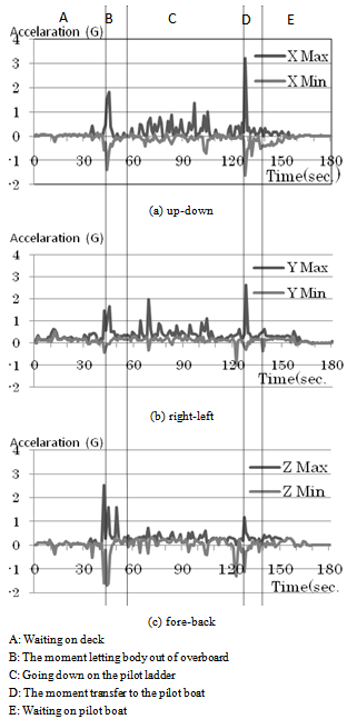 | Figure 10. The results of min. and max. acceleration in pilotage (x up-down) |
From Figures, the measured acceleration of leaving vessel is less than 1[G] toward Y axis (up-down). The method of leaving the vessel differs between Osaka and Ise-Mikawa. Ise-Mikawa regards the man rope as important, but Osaka in not. The difference of characteristics is able to read using body acceleration.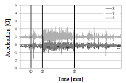 | Figure 11. The results of body acceleration in pilotage (x up-down) while taking the vessel (Ise-Mikawa Bay) |
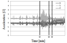 | Figure 12. The results of body acceleration in pilotage (x up-down) while leaving the vessel (Ise-Mikawa Bay) |
From the results, our evaluation using acceleration sensor is possible to read the performance of pilotage.
5. Conclusions
We attempted to find characteristics of the physical performance for leaving the vessel on the sea using 3 axes acceleration senor. As a result, we can confirm the pilot’s performance is as follows:•The largest value appears while moving from pilot ladder to pilot boat toward up-down of the body.•The influence of the wind for the physical performance finds using the acceleration sensor.•The acceleration toward fore and back is similar, the performance while down the pilot ladder is just up-down first and right-left.•While down the pilot ladder, the acceleration increases at center part of the ladder does not fixed point of the ladder.•The characteristics of body acceleration differ each transfer method.It is possible to monitor pilot’s performance using small sensor, and it relates to manage their fatigue and healthcare. Moreover, if we are able to monitor their mental stress, we can do the port management based on human aspect.In future research; we need more data to get more accurate results of Osaka and Ise-Mikawa Bay, and will compare the response relationship between candidates and professionals.Miniaturization of sensor of Proto-type is possible using Micro Electro Mechanical Systems (MEMS) technology; however, the data volume was large, and lots of time, 5-7 hours, needed to transfer to Personal Computer. In this point, we need new idea.
ACKNOWLEDGEMENTS
This research was supported by Japan Science and Technology Agency, ERATO, Maenaka Human-Sensing Fusion Project, University of Hyogo, Japan. We thank the pilot’s candidates of Osakaand Ise-Mikawabay pilot association. We also thank the editor of SAP Human Resource Management and all anonymous referees.
References
| [1] | International Maritime Pilots’ Association HP: |
| [2] | http://www.impahq.org/ |
| [3] | C.M.Irving FNI, “Marine Pilot Safety”, The Nautical Institute, 1995. |
| [4] | Japan Federation of Pilots’ Associations HP: |
| [5] | http://www.pilot.or.jp/index.html |
| [6] | Yuji Hayashi, Kuniomi Fujisawa and Koji Murai, “Occurrence Tendency of Marine Pilots' Personal Accidents on Board”, Journal of Japan Institute of Navigation, vol.121, pp.117-124, 2009. |
| [7] | Yuji Hahayashi and Koji Murai, “Occurrence Tendency of Pilots' Collision Incidents in Japan: In Cases of Kanmon Pilot District”, Journal of Japan Institute of Navigation, vol.119, pp.153-160, 2008. |
| [8] | Hiroyuki Nambu, Yuji Hayashi and Koji Murai, “Characteristic Analysis in Waters Happened Ship Collisions by Variable-Scale Cell Method : In Case of Osaka Bay Pilot District Except for the Inside of Harbor Limits”, Journal of Japan Institute of Navigation, vol.122, pp.97-103, 2010. |
| [9] | Shunsuke Fujii, Yuji Hayashi, Koji Murai and Harunobu Kenjoh, “Ship Collision Analysis along Sailing Routes using Segmental and Integrated Methods - In Case of Ise-Mikawa Bay Pilot District-”, Journal of Japan Institute of Navigation, vol.122, pp.105-111, 2010. |
| [10] | Takahiro Takemoto, Tomooki Nomura, Hideo Yabuki and Kazuki Inoue, “Characteristics of Pilot's Collision Avoiding Action and Prevention of Marine Collision Accidents”, Journal of Japan Institute of Navigation, vol.124, pp.47-55, 2011. |
| [11] | Tetsuro Saito, “New Education System for Pilot License and Revised Pilotage Law 2006 in JapanEducation System for Pilot License”, Navigation, Japan Institute of Navigation, vol.168, pp.39-44, 2008. |
| [12] | Kuniomi Fujisawa, Koji Murai, Yuji Hayashi and Kazusuke Maenaka, “Basic Study on Body Performance while Pilot Boat Transfer -Case of A Third Grade Pilot Candidate-“, Journal of Japan Institute of Navigation, vol.124, pp.21-26, 2011. |
| [13] | Koji Murai, Yuji Hayashi, Kohei Higuchi, Tsunemasa Saiki, Takayuki Fujita and Kazusuke Maenaka,“Basic Study of A Sea Pilot Candidate Performance Using Small Acceleration Sensor”, Proceedings of 2011 IEEE International Conference on Systems, Man and Cybernetics (IEEE-SMC2011), pp.179-183, 2011. |
| [14] | Koji Murai, Yuji Hayashi, Kohei Higuchi, Tsunemasa Saiki, Takayuki Fujita and Kazusuke Maenaka, “Evaluation of Teamwork for Simulator Training Based on Heart RateVariability - Case Study of A Cadet of Ship Navigator -”,International Journal of Intelligent Computing in Medical Sciences and Image Processing (IC-MED), vol.4, no.2, pp.93-100, TSI Press 2012. |
| [15] | Tsubasa Kobayashi and Nobuo Machida, “Measurement and evaluation of physical and mental workload in car driving”, The Japanese Journal of Ergonomics, vol.46, pp.190-191, 2010. |
| [16] | Takehiro Yamakoshi, Kenta Matsumura, Hiroyuki Kobayashi, Yujiro Gotoh and Hajime Hirose, “Feasibility Study on Assessment of Driver’s Stress from Differential Skin Temperature Measurement under Simulated Monotonous Driving”, Transactions of the Japanese Society for Medical and Biological Engineering, vol.48, no.2, pp.163-174, 2010. |
| [17] | ISO, “Ship and marine technology-Pilot ladders”, ISO799-2004 (E), 2004. |
| [18] | JIS, “Ship and marine technology-Pilot ladders”,JIS F2615, 2004. |
| [19] | JIS, “Pilot accommodation ladders”, JIS F2622, 2004. |
| [20] | http://www.freescale.com/files/sensors/doc/data_sheet/MMA7331L.pdf |
 Abstract
 Reference
 Full-Text PDF
 Full-Text HTML