-
Paper Information
- Paper Submission
-
Journal Information
- About This Journal
- Editorial Board
- Current Issue
- Archive
- Author Guidelines
- Contact Us
Geosciences
p-ISSN: 2163-1697 e-ISSN: 2163-1719
2018; 8(2): 44-50
doi:10.5923/j.geo.20180802.03

Experimental Performance Analysis of Ground Source Heat Pumps (GSHPs)
 Abstract
 Reference
 Full-Text PDF
 Full-text HTML
Hossein Lotfizadeh1, Soheil Porkhial2, Mohammad Reza Fathollahi3, Abbasali Abouei Mehrizi4, Majid Sanagoo Motlagh2, Sajjad Rezazadeh5, Babak Soltannia1
1Department of Mechanical Engineering, University of Alberta, Edmonton, Canada
2Department of Mechanical Engineering, Islamic Azad University, Karaj Branch, Karaj, Iran
3Department of Mechanical Engineering, K.N. Toosi University of Technology, Tehran, Iran
4Young Researchers and Elite Club, Karaj Branch, Islamic Azad University, Karaj, Iran
5Department of Mechanical Engineering, Islamic Azad University, Takestan Branch, Karaj, Iran
Correspondence to: Babak Soltannia, Department of Mechanical Engineering, University of Alberta, Edmonton, Canada.
| Email: |  |
Copyright © 2018 The Author(s). Published by Scientific & Academic Publishing.
This work is licensed under the Creative Commons Attribution International License (CC BY).
http://creativecommons.org/licenses/by/4.0/

Ground Source Heat Pumps (GSHP) have become as one of the most indispensable cooling and heating systems in residential applications since they have higher energy efficiency compared to the other conventional alternatives all around the world. In this study, a ground source heat pump system (GSHP) with the heat package unit model of GT018 FHP Manufacturing Co., was installed. The system setup included polyethylene U-bend ground heat exchanger pipes, nine drilled wells, and the pipes buried in soil at 15 m depth and in the cooling season of 2013. The system was tested, and its performance was reported. By the meteorological data, the values of humidity variations, air temperature, wells and water temperatures, relative humidity, and the system power supply were measured continuously for three months. The results showed that the adoption of GSHP system created a stable room indoor temperature of 25°C to 28°C. Furthermore, a great energy saving happened in the process, and the average coefficient of performance (COP) of 4.76 was achieved for the system that shows a suitable design and installation process.
Keywords: Ground source heat pump (GSHP), Experimental data, Performance, Coefficient of performance (COP), Efficiency
Cite this paper: Hossein Lotfizadeh, Soheil Porkhial, Mohammad Reza Fathollahi, Abbasali Abouei Mehrizi, Majid Sanagoo Motlagh, Sajjad Rezazadeh, Babak Soltannia, Experimental Performance Analysis of Ground Source Heat Pumps (GSHPs), Geosciences, Vol. 8 No. 2, 2018, pp. 44-50. doi: 10.5923/j.geo.20180802.03.
Article Outline
1. Introduction
- Ground source heat pump (GSHP) systems are known as one of the environment-friendly systems utilized in the world for the last decades. High initial costs limit the installation of these type of systems. It is noteworthy to mention that the energy costs are increasing and the obligation to mitigate greenhouse gases is inevitable which augments application of these systems. Performance analyses of the ground heat exchange systems and their design and installation are of paramount importance, and the main reason of their costs.In recent years, many researchers have studied the different aspects of GSHPs. Qing Gao et al. reviewed the progress of underground thermal energy storages (UTESs) compared to GSHPs, worldwide, and studied the development of GSHPs and the initiation of UTESs [1]. Meanwhile, they proposed a priliminary plan for future development of UTESs in China. Karabacak et al. installed a GSHP system with U-bend pipes in Denizli city, Turkey [2]. They determined the performance coefficients of the heat pump and the system. They also measured the values of solar radiation, external temperature, relative humidity, and wind speed and reported the results. Yu et al. designed and produced a constant temperature-, air-conditioning-, and humidity controling system driven by ground source heat pumps in an archive building in China [3, 4]. They measured convected heat to the vicinity soil, evaluated the energy cost of GSHP, and showed that decrease in the soil temperature, at the middle of two boreholes, is proportional to increase of distance between two boreholes, and suggested an optimum distance between two boreholes in Shanghai. Benli designed and installed a horizontal closed-loop GSHP system with a latent heat thermal storage tank located in Turkey [5]. He showed that the utilization of GSHP-PCM is suitable for greenhouse heating in this district. Zhai and Yang built a GSHP system in Shanghai, China, for two years [6]. In their study, the operating cost of the GSHP system was compared to an air source heat pump system. They also analyzed the applications of GSHP systems corresponding to different climate zones, in China. Bansal et al. proposed a new term to evaluate deterioration of thermal performance of earth air tunnel heat exchanger (EATHE) under transient operating conditions, in India [7]. They obtained maximum air temperature drop, experimentally and numerically. Pulat et al. evaluated the performance of horizontal GSHP by considering various system parameters for winter season, in Bursa, Turkey [8]. They obtained preliminary numerical temperature distribution around GHE pipes and compared the results with conventional heating methods in the economic analysis. Aikins et al. analyzed the certified heat pump units in the Republic of Korea [9]. They suggested to revise certification standard concerning underground flow-rate circulation to save energy and reduce the installation costs of GSHP systems in the Republic of Korea. Michopoulos et al. installed a GSHP system in Northern Greece over an eight-year operation period [10]. They estimated the performance of the system as well as the seasonal energy efficiency ratio (SEER) and compared the results to a conventional heating and cooling system for the building. Yang investigated the performance characteristics of a vertical U-bend direct-expansion (DX) GSHP with buried copper piping and compared the results to the conventional ground coupled heat pump (GCHP) system in China [11]. Kim et al. evaluated the performance, temperature, the relative humidity and the coefficient of performance (COP) of a closed vertical GSHP system installed in Korea [12]. They proved that the ground temperature was almost constant below 10 m in depth. Zhu et al. compared the deterministic and the probabilistic methods for a GSHP in Pensacola, FL, based on Monte Carlo simulation [13]. They tried to find out the impact of data variation and discrepany on results of their analyses, and concluded that the GSHP option was more economic than a conventional single zone split system having heat pumps utilization, in long term applications. Kim et al. introduced a new method for verification of the actual operating performance of a GSHP system installed at the KIER site in Korea [14]. They compared the actual performance with the manufacturer’s data output including the entering water temperature (EWT), leaving water temperature (LWT), capacity, flow-rate, power, and coefficient of performance (COP), based on the ISO standards. Kharseh et al. calculated the heating and cooling of a reference building for different global warming scenarios in different climates and compared the prime energy required to drive the GSHP system for each scenario and two configurations of ground heat exchangers [15]. Madani et al. studied and simulated three control methods for a GSHP system based on the climate condition in one year [16]. They also compared the controlled temperature and the saved energy of these methods with each other.Although several researches are available regarding GSHP, a few researches have studied residential applications of GSHPs, and evaluated their coefficient of performance as well as the system efficiency. In this paper, the usage of GSHP with vertical closed loop system for residential applications is investigated and the installation process is briefly explained. Utilizing a control system containing a PC, a data acquisition system (DAS), and different sensors installed in different parts of the system, the inlet and outlet temperatures of the pipes, the room temperature, the wells temperature, power of the system, and the inside and outside humidity are collected and recorded experimentally for three months. Also, the system COP and the system efficiency are measured and presented.
2. The System Description
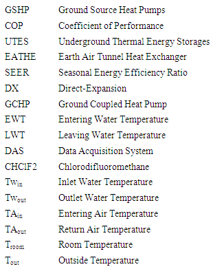
- Generally, the GSHP contains three pipe loops. These loops are presented in Figure 1, for the heating mode. The first loop is the distribution loop that gets the energy from the refrigerant loop and transfers it to the temperature-controlled space (building or room). The second loop is the refrigerant loop which is a sealed loop to transfer energy from one point to another in the circuit and contains compressor and expansion valve. In the heating mode, the first loop works as an evaporator, and the third loop works as a condenser for the refrigerant loop. The third loop is a ground loop which can be closed or open loop. A closed loop usually contains water and the antifreeze solution circulated under the ground which absorbs heat from the ground and transfers it to the refrigerant loop in heating mode during the winter. Sometimes an extra loop will be added to the original loops to supply domestic hot water.In this study, a vertical closed loop GSHP system is installed. The city is famous for its mild sunny summers and cold winters. The GSHP is the water-air type which uses water for the ground loop and air for the distribution loop.The installed GSHP is applied for a 25 m2 (5m×5m) room as the understudy heating environment. The experimental setup consists of underground heat exchangers, circulation water pump, circulation water tank, emergency water heater for extremely cold air, compressor, water tank, heating channels that distributed the warm air in the greenhouse and controlling system (consisting a PC, data acquisition system, and sensors). Furthermore, GT018 of FHP Manufacturing Co. (Fort Lauderdale, FL) with R-22 (Chlorodifluoromethane—CHClF2) as refrigerant was used as the heat pump packaged unit (Figure 1).
 | Figure 1. Heat pump loops and operation in the heating mode |
2.1. Pipeline Installation
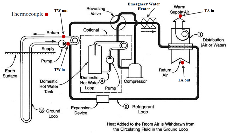
- To set up the ground heat exchanger, U-shaped polyethylene pipes (60 mm in internal diameter) buried at nine wells with the depth of 15 m and the diameter of 80 cm. The distance between each U-shaped pipe was 40 cm to minimize the interference between them. Finally, the remaining parts were installed, and the pipes were connected into the pump circulator. Figure 2 shows the drilled wells and schematic of the installed GSHP pipelines, also the heat pump and controlling devices.
 | Figure 2. Installed GSHP system: A) Drilled wells and schematic of the mounted pipelines. B) Heat pump and contorting devices and sensors |
2.2. Measurements
- Considering the above installed GSHP system, the following data was recorded regularly using a 30 min time interval for three months:• The temperature of the entering and leaving water to the underground heat exchanger (GHE) using copper-constantan thermocouples which were mounted on the unit fluid inlet and outlet lines.• Measurement of the entering and leaving air temperature.• Measurement of the nine wells average temperature• Measurement of indoor air temperatures and the humidity using a multi-channel digital thermometer.• Measurement of outdoor air temperatures and the humidity in the southern side by using a multi-channel digital thermometer.• Measurement of the electrical power supply by a data logger.
3. Results and Discussion
3.1. Recorded Temperature Variations
- The recorded temperature data from the sensing units is indicated in Figure 3.
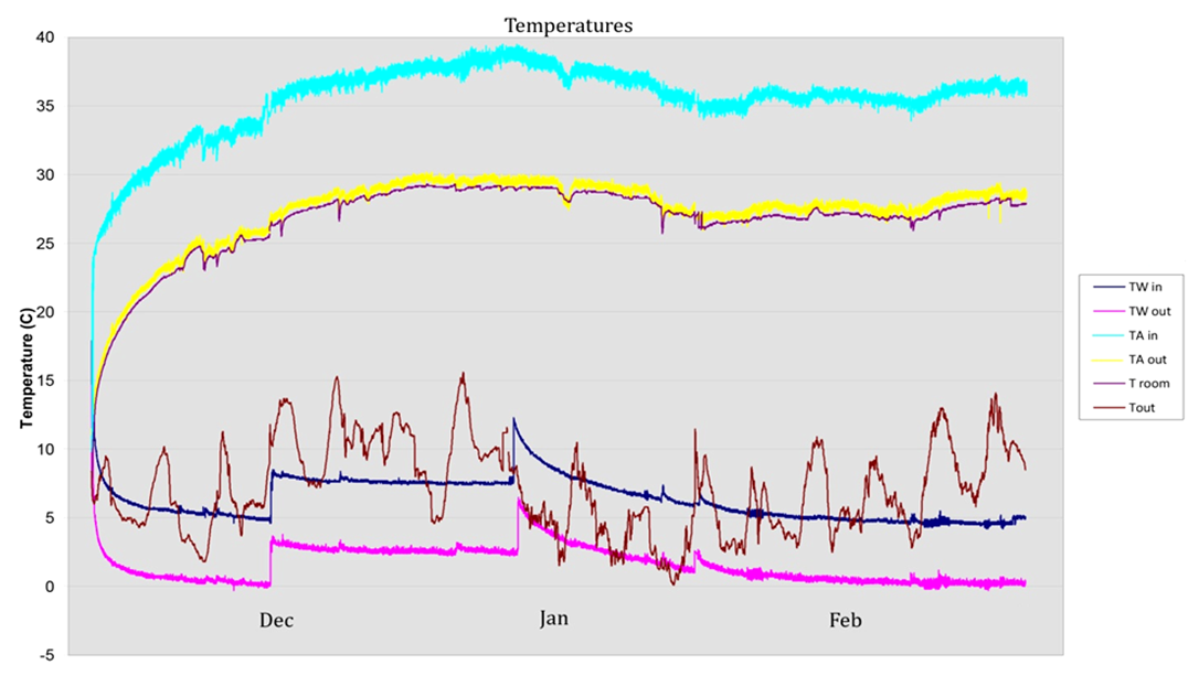 | Figure 3. Temperature measurements |
3.2. Wells Temperature
- The wells temperatures were also measured. Figure 4 demonstrates the average temperature of the wells during the test period. Temperature measurement sensors were installed in three different heights of each well that made the average wells temperatures recordable. Considering the water cycle in the wells, the circulating water enters the wells (here we mention the phrase “well” instead of “pipeline inside the well” for summarizing) with a low temperature and absorbs the heat from the ground which can be considered as a higher energy source. This phenomenon increases the temperature of the water. It means that the first well has higher thermal gradient compared to the other wells. Well 21 was the first well in which the water cycle was started; therefore, the curve has dropped faster than the other wells. However, due to the increase in water temperature, the circulating fluid would flow to the next well with a higher rate. Thus, the next curve should be at a higher level compared to the previous well curve. The trend is shown in Figure 4.
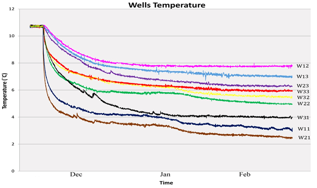 | Figure 4. Wells temperature |
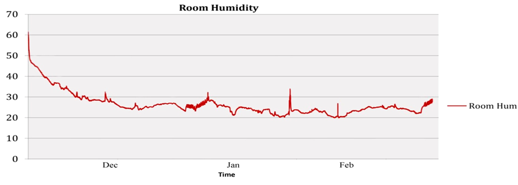
3.3. Room Humidity Variations
- The room humidity is shown in Figure 5. After almost 15 days, the room humidity gradually decreased from 60% to less than 30%. However, it eventually fluctuated between 20% to 30%. Based on the fluctuation rate, the results show that humidity was also reached a suitable range for the human.
 | Figure 5. Room humidity Variations |
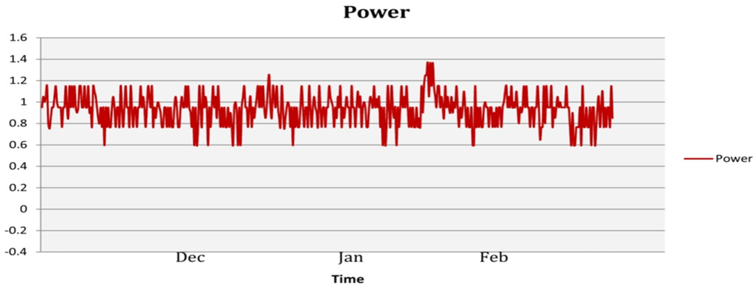
3.4. Energy Efficiency Evaluation
- The power supplied for the system was also recorded, and the results are shown in Figure 6. As it can be seen in Figure 6, the reported values were similarly recorded as the previous items. By neglecting the small rate of changes, the system has consumed a constant power value.
 | Figure 6. Power supply variation diagram (in kW) |
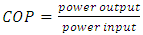 | (1) |
 | (2) |
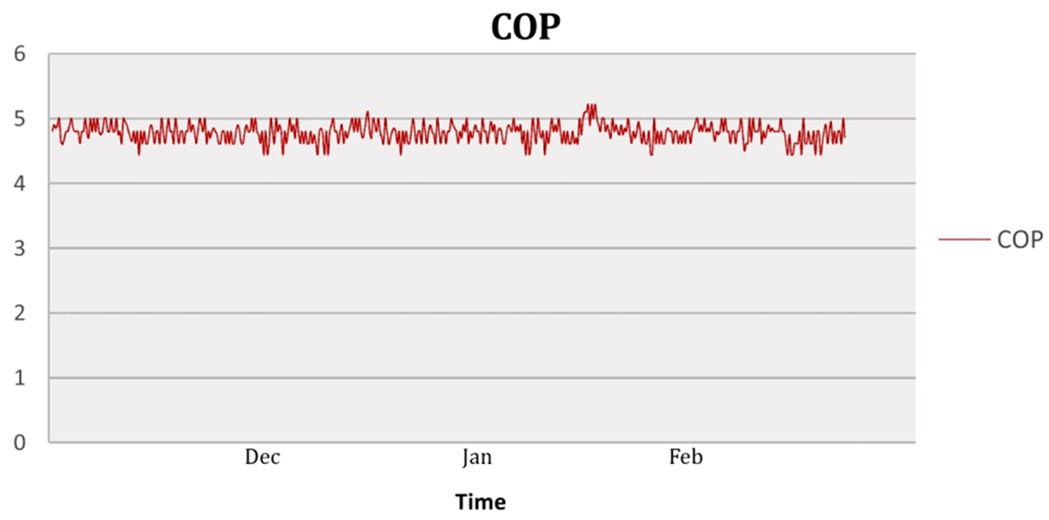 | Figure 7. COP of the installed GSHP |
4. Conclusions
- A vertical closed loop GSHP was installed in a cold season. For this purpose, nine wells with the depth of 15 m and the diameter of 80 cm were drilled and U-shaped polyethylene pipes buried in the water of the well as the system heat exchanger, circulating fluid through the pipelines in the wells. The system was utilized to heat a 25 m2 test space. In this study, the inlet and outlet water temperature from/to the wells, the entering and leaving air temperature from/to the heat pump package unit, the room temperature and humidity, and the outside temperature were recorded continuously for three months. Water temperature leaving the heating package unit showed a lower rate of changes compared to the outside temperature variation which was attributed to the high specific heat capacity of water.The results showed that the uncontrolled outside temperature with the range of 2-15°C was reached into a controllable and steady room temperature of 26-28°C which is a desired temperature for living conditions. The supplied power of the system was also reported according to the room temperature increases.The average temperature of all nine drilled wells were also recorded and reported. According to the results, the water temperature increased as it was circulated through the wells. The average of difference between input and output temperatures of the nine wells was 4.4°C. Besides, the fluctuation of the room humidity was also recorded. In the diagram, the room humidity decreased from 60% to less than 30% (between 20% to 30%) within 15 days. Moreover, considering the power supply results, the COP of the system was calculated, and the average of 4.76 was obtained. Achieving the average COP of higher than 4 for the current GSHP system shows that an indispensable design and installation has been performed and means that the system has a positive effect on the energy saving and has operated more efficiently. This work can be used as bench mark for the future studies in the field of geoscience, and energy-related investigations.
Table of Nomenclatures