-
Paper Information
- Paper Submission
-
Journal Information
- About This Journal
- Editorial Board
- Current Issue
- Archive
- Author Guidelines
- Contact Us
Geosciences
p-ISSN: 2163-1697 e-ISSN: 2163-1719
2017; 7(5): 141-149
doi:10.5923/j.geo.20170705.01

Geoelectrical Survey of Ground Water in Some Parts of Kebbi State Nigeria, a Case Study of Federal Polytechnic Bye-Pass Birnin Kebbi and Magoro Primary Health Center Fakai Local Government
 Abstract
 Reference
 Full-Text PDF
 Full-text HTML
Emmanuel Hassan, Jitendra Kumar Rai, Uchenna Okwudili Anekwe
Department of Physics, University of Science and Technology, Aliero, Nigeria
Correspondence to: Emmanuel Hassan, Department of Physics, University of Science and Technology, Aliero, Nigeria.
| Email: |  |
Copyright © 2017 Scientific & Academic Publishing. All Rights Reserved.
This work is licensed under the Creative Commons Attribution International License (CC BY).
http://creativecommons.org/licenses/by/4.0/

Schlumberger array is the most commonly used among other arrays for Vertical Electrical Sounding (VES) and it requires large spacing at both ends for deeper subsurface information. The problem of limited space for spreading in built up areas could lead to incomplete information from deeper depth. The Geolectrical survey involving electrical resistivity methods has been carried out at Birnin Kebbi and Fakai Local Government Area in Northern Nigeria with the view to delineate the Geoelectrical characteristics of basement complex and sedimentary formation to evaluate it ground water potential in the areas. A total of two (2) Vertical Electrical Sounding (VES) station were established within the site along two (2) traverses. The Schlumberger configuration was used for the data acquisition. The half current electrode (AB/2) used range from 1 to 100 meters. The quantitative interpretation of the VES curves involved the use of partial curve matching and the 1-D computer iteration technique. The depth sounding interpretation results were used to generate Geoelectric sections from which the aquifer was delineated. The Geoelectric sections drawn from the result of the interpretation revealed five (5) subsurface layers for Birnin Kebbi and four (4) layers for Fakai Local Government Area which comprises of top soil, schist, lateritic sand, partially weathered, weathered and fractured basement. The weathered and fractured layers constituted aquiferous zone in all the stations. Hence from the research work it is recommended that boreholes can be sited in high conductivity zone in VES 1 and VES 2 as they contain probable aquifers. The depth of any borehole should be located between 15m to 30m to advantage of basement fractures.
Keywords: VES, Resistivity, Schlumberger array, Aquifer, Groundwater
Cite this paper: Emmanuel Hassan, Jitendra Kumar Rai, Uchenna Okwudili Anekwe, Geoelectrical Survey of Ground Water in Some Parts of Kebbi State Nigeria, a Case Study of Federal Polytechnic Bye-Pass Birnin Kebbi and Magoro Primary Health Center Fakai Local Government, Geosciences, Vol. 7 No. 5, 2017, pp. 141-149. doi: 10.5923/j.geo.20170705.01.
Article Outline
1. Introduction
- In most of the countries, there is not only a heavy reliance on ground water as a primary drinking supply but also as a supply of water for both agriculture and industrial use. The reliance on groundwater is such that it is necessary to ensure that there are significant quantities of water and that it is of a high quality. The use of geophysics for both groundwater resource mapping and for water quality evaluations has increased over the last 15 years in large part due to the rapid advances in microprocessors and associated numerical modeling solutions. However despite its spectacular success, for the majority of groundwater studies, the use of geophysics is still often not considered.Groundwater has been exploited by mankind since the beginning of time and it is estimated that around 700 billion m3 are drawn out of the earth’s aquifers each year. This makes groundwater by weight, the primary mineral extracted from the earth. Groundwater has many advantages over surface water. Qualitative, because of the presence of protective surficial geological formations, their depth, filtering capacity of most of their reservoirs and the clogging of river banks, aquifer groundwater is generally better protected than surface water from massive pollution. The physicochemical quality and the temperature of groundwater are relatively constant and in some case it can be consume without even bacteriological treatment. Economically, in countries having many aquifer, water is easily attainable, does not require long pipelines and thus involves lower pumping, treatment and energy costs.
1.1. Electrical Resistivity Method
1.1.1. Wenner Array
- The Wenner array consists of four collinear, equally spaced electrodes. The outer two electrodes are typically the current (source) electrodes and the inner two electrodes are the potential (receiver) electrodes. The array spacing expands about the array midpoint while maintaining an equivalent spacing between each electrode. The advantages of the Wenner array are that the apparent resistivity is easily calculated in the field and the instrument sensitivity is not as crucial as with other array geometries. Relatively small current magnitudes are needed to produce measurable potential differences.The disadvantages are that for each sounding, all of the electrodes have to be moved to a new position. In order to image deep into the earth, it is necessary to use longer current cables; handling the cables and electrodes between each measurement can be cumbersome, especially in difficult terrain. The Wenner array is also very sensitive to near surface in homogeneities which may skew deeper electrical responses. The Wenner array is a labor-intensive survey because of the cable lengths required and the movement of the electrodes during the survey. Substantial lengths of cable energized with current at high voltage present a safety hazard.
1.1.2. Schlumberger Array
- The Schlumberger array consists of four collinear electrodes. The outer two electrodes are current (source) electrodes and the inner two electrodes are the potential (receiver) electrodes. The potential electrodes are installed at the center of the electrode array with a small separation, typically less than one fifth of the spacing between the current electrodes. The current electrodes are increased to a greater separation during the survey while the potential electrodes remain in the same position until the observed voltage becomes too small to measure. Typically, expanding the current electrodes occurs roughly six times per decade. The advantages of the Schlumberger array are that fewer electrodes need to be moved for each sounding and the cable length for the potential electrodes is shorter. Schlumberger soundings generally have better resolution, greater probing depth, and less time-consuming field deployment than the Wenner array. The disadvantages are that long current electrode cables are required, the recording instrument needs to be very sensitive, and the array may be difficult or confusing to coordinate amongst the field crew. Substantial lengths of cable energized with current at high voltage present a safety hazard. The Schlumberger array is a labor-intensive survey because of the cable lengths required and the movement of the electrodes during the survey.
1.2. Objectives of the Study
- 1- To investigate the aquifer characteristics, thickness, layer wise soil type, ground water quality (by conductivity value) and water table depth using Vertical Electrical Sounding (VES) resistivity survey technique.2- To determine the geoelectric and hydrogeologic characteristic of the aquifer present in the study area.3- Detecting and mapping water saturated layer in various type of shallow aquifer.
1.3. Literature Review
- Adequate groundwater exploration can be considered as one of the primary components of the groundwater management practices. The assessment of the aquifer potential both on the basis of quality and quantity is of utmost importance. Resistivity survey can be used as an initial step for assessing the aquifer potential to promote the sustainable groundwater usage.This chapter deals with the review of relevant literature in relation to the study. This includes the concept of groundwater occurrence and movement, groundwater use in the study area.
1.4. Electrical Method
- Electrical and electromagnetic techniques have been extensively used in groundwater geophysical investigations because of the correlation that often exist between electrical properties, geologic formations and their fluid content Flathe, [1] Zohdy, [2] Flathe, [3] Ogilvy [4] Zohdy et al, [5] Fitterman and Stewart, [6] McNeill, [7]. Most electrical techniques induce an electrical current in the ground by directly coupling with the ground. The resulting electrical potential is then used to measure the variation in ground conductivity, or its inverse, resistivity. Different materials, and the fluids within them, will show different abilities to conduct an electric current. In general, sequences with high clay content show higher conductivity as do saturated sequences and especially sequences where saline (or sometimes other contamination) fluids are present. Common field practice for electrical surveying relies on directly placing an electrical current into the ground (direct current electrical resistivity surveying) and measuring the response (the electrical potential drop) to that current over a set distance.The typical results of electrical surveys are electrical profiles or geo-electric images and geo-electric depth soundings. The profile or transect method for mapping lateral resistivity changes is now largely replaced by electromagnetic techniques as the electrical technique is slow (when probes have to be placed directly into the ground) and thus is not cost effective relative to the electromagnetic techniques. Electrical methods are still widely used however for conducting soundings and electrical cross-sections.Electrical techniques can be divided into a number of types based on the configuration of the electrodes that are used to input the electrical currents into the ground and the nature of the electrical signature. Only the basis of direct-current electrical resistivity techniques will be discussed here without a review of the different electrode configurations.
1.5. Direct Current Resistivity Method
- The direct-current (DC) electrical resistivity method for conducting a vertical electrical sounding (VES) has proved very popular with groundwater studies due to the simplicity of the technique and the ruggedness of the instrumentation. An excellent example of the use of the technique was shown in a survey for a rural water supply in northern Nigeria. Before the vertical electrical sounding was used a failure rate of over 82% was recorded for boreholes. With the geophysics and a combination of geological and photo geological inspection this was dramatically reduced to less than 20% failure. Van Overmeeren [8] showed the use of electrical measurements in mapping boundary conditions in an aquifer system in Yemen. Beeson and Jones [9], Olayinka and Barker [10], Hazell et al. [11] Barker et al. [12] and Carruthers and Smith [13] all have demonstrated the use of electrical techniques for siting wells and boreholes in crystalline basement aquifers throughout sub-Saharan Africa. Other similar examples are given by Wurmstich et al. [14] Yang [15], and Yang et al. [16]. Some research work demonstrated a useful development of electrical techniques by considering the conductance of the DC section as a guide to overall aquifer potential for mapping groundwater resources in the Kalahari Basin. This type of approach may find applicability in many mafic-basin groundwater studies. Sauck and Zabik [17] have demonstrated a development of the sounding technique by conducting azimuthal surveys. This method was successfully used to assess the directional variation in hydraulic conductivity of glacial sediments in Switzerland. A similar approach has been tested by Marin et al. [18].During the late 1990's methods were developed for continuously acquiring electrical data by using a pulled electrical array Sorensen [19].Obiora and Nwoka [20] conducted a research study in southeastern Nigeria sedimentary basin within rain forest belt of Nigeria to determine the depth to the water table, aquifer thickness and subsurface geology for the groundwater distribution as well as its potential as a substitute to the surface water resources. A total of 38 VES were carried out near already drilled bore wells in the study area with maximum electrode spacing (AB/2) of 500 m by adopting Schlumberger electrode configuration technique. The instrument used was the ABEM SAS 300 B, which gave a direct readout of resistance.He collected the lithological logs of already existing boreholes, evaluated and carried out comparison with the VES data. Five types of sounding curves were identified from the study area based on Geoelectrical and geological succession. Based on results, he subdivided the area into three cells of distinct litho-stratigraphic units:Sandy area (Cell I), sand-gravelly sequence (Cell II) and clay-sand unit (Cell III) and presented in an overburden thickness map. He revealed from the results that the study area was underlain by coastal sands (Benin formation). The water table varied from 10 to 64 m and thickness of the aquifer ranged from 20 to 80 m. He concluded that the study area was an excellent source of groundwater supplies.Groundwater is defined as the subsurface water that occurs beneath the water table and flows through voids in the soils and permeable geologic formations that are fully saturated.
2. Material and Methodology
2.1. Materials
- The Geoelectrical survey was carried out on 11/06/2015. Using the following equipment acquired from the ministry of Rural urban water agency (RUWSSA). In the research work, the Schlumberger array was adopted. The equipment used for the survey is: 1. Terra-meter SAS 300C2. Coiled wire3. Tape4. Hammer 5. GPS Meter6. Current and potential electrodes7. D.C Battery 12volts
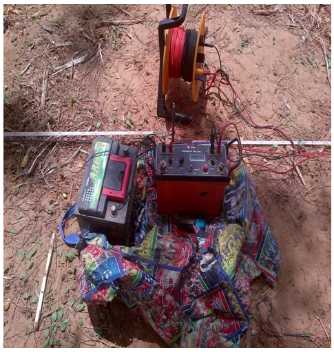 | Figure 1. The survey setup at the site |
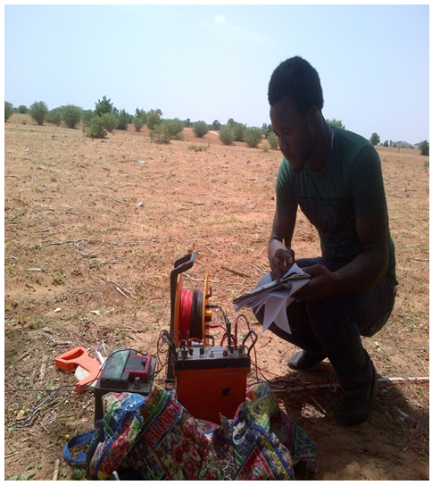 | Figure 2. The survey |
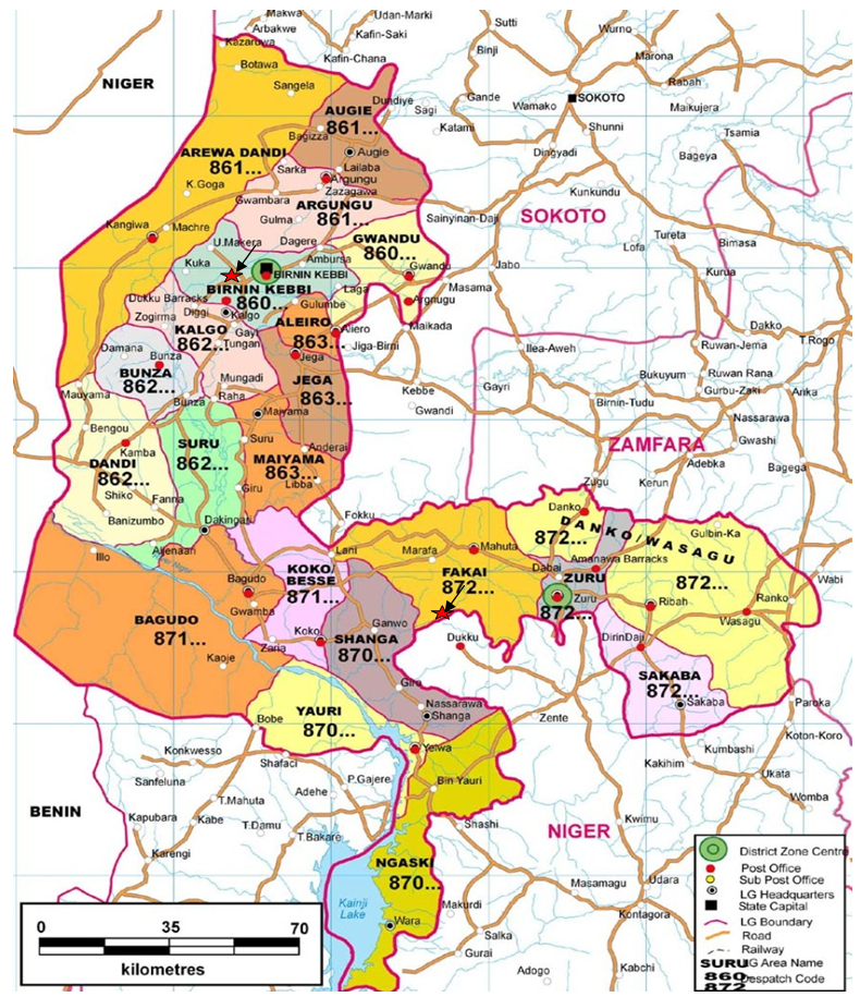 | Figure 3. Geologic Map of the studied area: Source (Google maps) |
2.2. Procedures
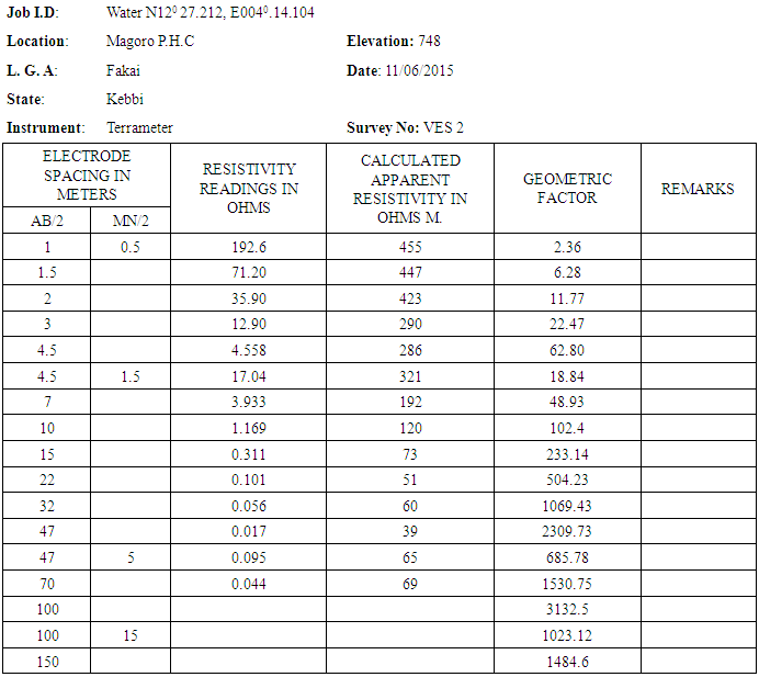
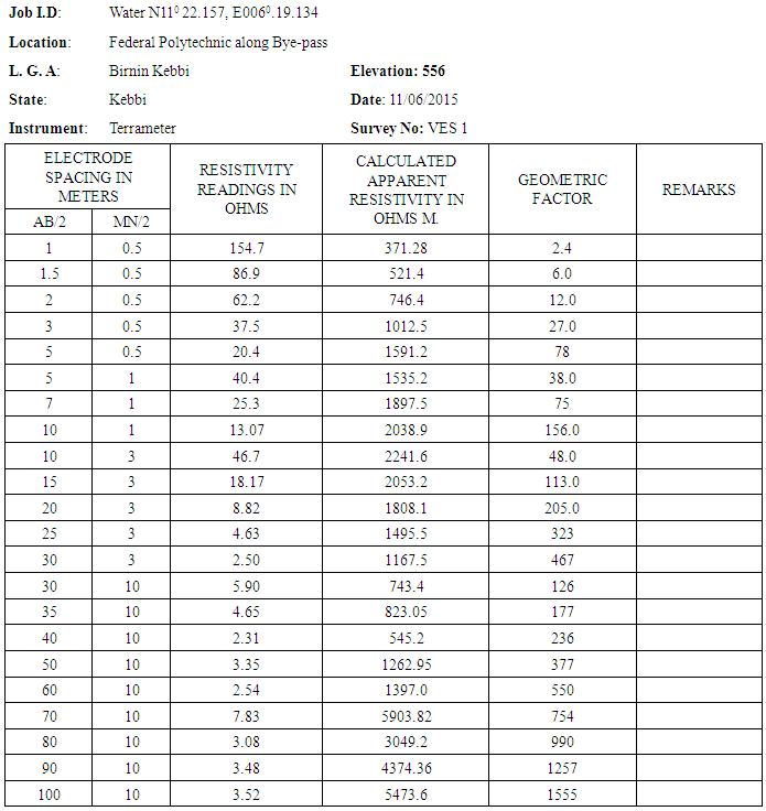
- 1. A leveled terrain in the VES station was located and the Schlumberger array was used for the present study.2. The four electrodes were positioned symmetrically along a straight line i.e. the current electrodes (C1 and C2) on the outside and the potential electrodes (P1 and P2) which are also the inner electrodes place in between C1 and C2.3. The Terra-meter was powered by DC source and further adjustments on the terra-meter were made such as: setting the number of circle to 4, automatic reading of values in ohms and sending a 50mA of current into the ground.4. To change the depth range of penetration, the current electrodes were displaced outwards while the potential electrodes remained fixed.5. When the ratio of the distance between the current electrodes to that of the potential electrodes became too large, the potential electrodes were displaced outwards otherwise the potential difference becomes too small to measure with sufficient accuracy.6. The configuration used is given in the VES table.7. The maximum current electrode spacing (AB/2) was 100m and the terrameter was used to measured and record the resistance of the subsurface.8. The values of the resistance obtained in the field were multiplied with their respective Geometric factor (k) which gave the required apparent resistivity results.9. The required data was plotted on a log-log graph sheet and the resultant curve was quantitatively interpreted.10. The GPS was used in locating the longitude and latitude of each VES station. 11. These steps were repeated at subsequent VES12. The sounding was done on 11/06/2015
2.3. Calculation
- The data were calculated using the equation below. For calculating of Geometric factor (G), the following formulae was used.
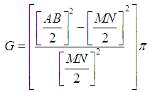 AB is the distance (m) between the two current electrodesThe distance from the midpoint to the electrode A and the distance between the electrodes B is the AB.MN is the potential electrodesMN electrodes spacing between MN from the midpointThe midpoint is a constant point for the current electrode and the potential electrodes.Π is a constant= 3.142Apparent resistivity is calculated using ohms lawApparent resistivity = Resistance reading × geometric constant
3. Result and Interpretation
3.1. Result
|
|
3.2. Graph
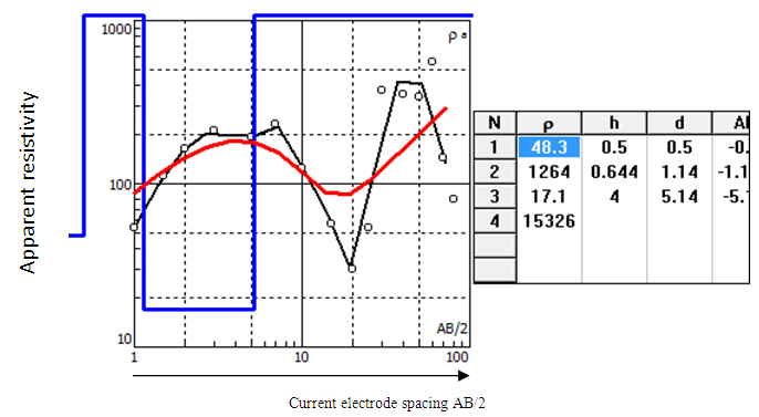 | Figure 4. Graph of apparent resistivity versus electrode spacing: Source (IPI2WIN Software) |
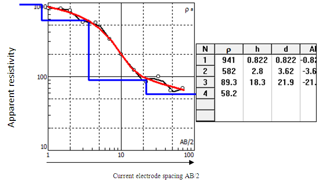 | Figure 5. Graph of apparent resistivity versus electrode spacing: Source (IPI2WIN Software) |
3.3. Interpretation
- The first step in the interpretation of a resistivity sounding survey is to plot on log-log sheet a graph of apparent resistivity against the current electrode spacing (AB/2). The interpretation of a resistivity sounding survey is to classify the observed apparent resistivity curves into types. This classification is based on the basis of the shapes of the curves, but at the same time it is related to the geological situation in the subsurface. The shape of the VES curve depends on the number of layers in the subsurface and thickness of each layer.
|
|
4. Discussion
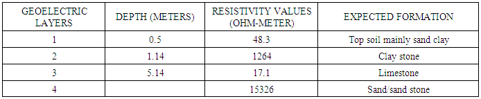
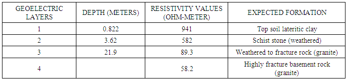
- The interpretation of field resistivity data are in terms of resistivity’s and depth to the bedrock and interfaces across which a strong electrical anomalies exists. The analysis and the interpretation of the surveyed data shows the presence of multi- layers in the sedimentary formation, having a maximum of four Geoelectrical layers, consisting mainly of various form of clay and sand, also a maximum of four Geoelectrical layers under the basement complex terrain was delineated. These layers are; (i) Top soil which consists of clayed sand and lateritic clay (ii) The second is the fresh/ highly resistive basement. The fresh basement is characterized by high and infinite resistivity value and could not be contended on/for groundwater, (iii) the weathered zone consisting of decompose schist, (iv) fracture basement which has lower resistivity value constitute good water zone and highly decompose schist or granite. The resistivity values and ranges for each of the mentioned formations are given in the above tables. Profile (VES 1) shows a potential ground water body at a depth after 5.14 meters from the top of the ground surface. While second profile (VES 2) indicates potential ground water body after 21.9 meters of the depth below the ground surface.However, the second place at federal Polytechnic bye pass has no concrete evidence of the ground water pressure apart from it general geological inference of fractured subsurface basement rocks.
5. Conclusions
- The method of investigation adopted in this study has helped in the identification of the aquiferous units and has provided an understanding of aquifer dimension especially the thickness of the weathered basement, the depth to bed rock and fractured zones which are required for locating points with high potentials for groundwater occurrence. The geophysical investigation survey and the local geology of the study area, reveal the geo-electric parameters established through the computer analysis that the sounding points is hydro logically prolific especially in VES 2. From the analysis, the thickness of fractured and weathered basement in magoro and part of fakai L.G.A is small and can only accommodate shallow aquifer which shows that the area has poor groundwater potential, but VES 2 in part of Fakai L.G.A has very thick layer of weathered/fractured basement and therefore promising good quantity of groundwater source. The underground water condition of the study areas shows that water could be seen in region of weathered/fractured basement that were delineated.
6. Recommendations
- The investigation will serve as an avenue to update groundwater data bank of the study area for those whose responsibility is the provision of safe drinking water to the entire populace around the area. It will also help in planning agricultural practices in advising the farmers on choosing the appropriate crops to be cultivated around the study area.
ACKNOWLEDGEMENTS
- With much gratitude to God Almighty for given us the opportunity to complete our research work. I will like to acknowledge all our reviewers and those who supported and encouraged us throughout the success of this research work.