Rakesh Kumar Yadav, Swami Saran, Daya Shanker
Department of Earthquake Engineering, Indian Institute of Technology Roorkee, Roorkee, India
Correspondence to: Daya Shanker, Department of Earthquake Engineering, Indian Institute of Technology Roorkee, Roorkee, India.
| Email: |  |
Copyright © 2017 Scientific & Academic Publishing. All Rights Reserved.
This work is licensed under the Creative Commons Attribution International License (CC BY).
http://creativecommons.org/licenses/by/4.0/

Abstract
In this paper the interference and interaction of footings among themselves is studied. This included: factors affecting bearing capacity, settlement and tilt of shallow foundations in static as well as dynamic conditions and evaluation of ultimate bearing capacity, settlement and tilt by non-linear constitutive law. Further interference between two parallel shallow footings based on spacing between them is studied and variation of bearing capacity ratio with height of the applied load to width ratio of footing is plotted.
Keywords:
Interference, Tilt, Maximum settlement
Cite this paper: Rakesh Kumar Yadav, Swami Saran, Daya Shanker, Interference between Two Adjacent Footings Located in Seismic Region, Geosciences, Vol. 7 No. 4, 2017, pp. 129-140. doi: 10.5923/j.geo.20170704.03.
1. Introduction
The phenomenon of interference of adjacent footings is of greater practical significance as footings in field are rarely isolated and they interfere with each other to some extent. Due to interference, unequal stress concentrations occur below a footing which causes tilting and it changes the behavior of the footings. In frictional soils, numerous investigators have used model tests or theoretical methods to study the interference effect for two/three strip footings. The interference effect on the ultimate bearing capacity of two nearby strip footings was studied theoretically by STUART (1962) considering limit equilibrium method, which could be considered as the pioneering work in this area. He reported that, as the two adjacent footings were placed closer to each other, the ultimate bearing capacity of each individual footing was increased relative to that of an isolated footing. He explained this response as the development of an inverted arch within the soil between the two footings. The foundations are basically designed based on two criterion namely Bearing Capacity and Settlement criterion. Many classical theories have been postulated for the isolated foundations by many pioneers like TERZAGHI (1943), MEYERHOFF (1963), HANSEN (1970) and VESIC (1973). In general as per the TERZAGHI (1943), when an isolated shallow foundation is loaded, the stress or the failure zone in the foundation soil extends in horizontal direction on either side of the footing to about twice the width of the footing and in vertical downward direction to about thrice times the width of the footing. Many theories are available to find ultimate bearing capacity of two and three interfering strip footings loaded simultaneously with equal loads (STUART, 1962; MANDEL, 1963; WEST and STUART, 1965; AMIR, 1967; SIVA REDDY and MOGALIAH, 1976).DASH (1981) investigated the problem of determining the ultimate bearing capacity of two strip footings, when one of the footing carrying certain load located nearby. No method has been reported to find settlement and tilt of interfering footings except finite element method and finite difference technique.Many investigators have experimentally studied the problem of two and three interfering footings loaded simultaneously (STUART, 1962; WEST AND STUART, 1965; DEMBICKI et. al. 1971; SARAN AND AGRAWAL, 1974). The effect of footing carrying certain load on the behavior of adjacent footing has also been studied experimentally by few investors (MURTHI, 1970; and DASH, 1990). KOUZER AND KUMAR (2010) have created investigative procedure to decide an ultimate load of a footing by observing the interference of an existing footing on sand. SAIBABA et al. (2012) evaluated the results of series to study the effect of spacing between footing on settlement also described by considering two same size footing placed adjacently to each other which were loaded with same load intensities. In past AMIR (1992) has studied the effect of two and three interfering footings on ultimate bearing capacity, settlement and tilt of footing for clay and sand both. He has found that ultimate bearing capacity of interfering footing is almost same as of isolated footing in case of clay, while it is higher in case of sand. He has concluded that magnitude of settlement and tilt of the interfering footings is affected by S/B ratios.In all above mentioned investigations, footings were subjected only vertical loads, i.e. interference studies were limited to static case. In the knowledge of authors, no work has been carried out considering footing located in seismic region. In the present investigation interference study between two footings have been carried out when these are located in seismic region. For this purpose pseudo-static analysis has been carried out.
2. Statement of the Problem
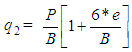
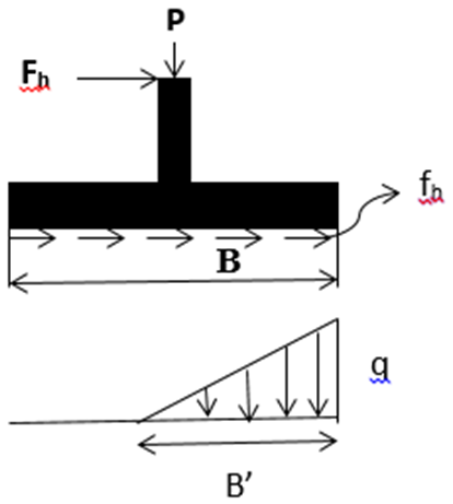
Figure 1 shows two adjacent footings having clear spacing ‘S’ and subjected by equal amounts of load ‘P’.Since the footings are located in seismic region each of these will be subjected to seismic force ‘Fh’ acting at a height ‘h’ from the base footing as shown in Fig. 1.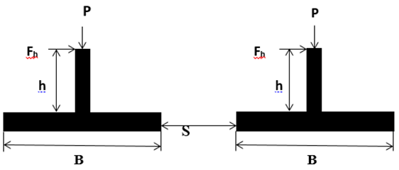 | Figure 1. Shows two adjacent footings of equal width B located in seismic region and resting on saturated clay |
Due to unequal concentration of stresses below the base of each footing, both footings tilt in inward direction as shown in Fig. 2, because settlement at the inner edge of the footing is greater as stresses increased at inner edge due to new placed footing. Each footing is assumed to have equal amount of the load say ‘P’. S represents the amount of clear spacing between footings.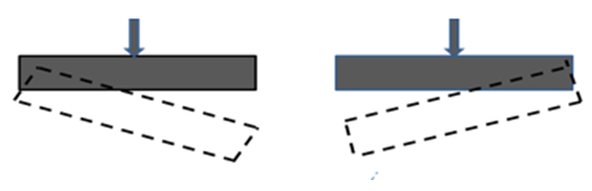 | Figure 2. Tilting of footing in inward direction |
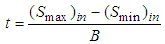
Pseudo-static analysis has been carried out to solve the problem, i.e. it is based on the concept of seismic coefficients, and only horizontal seismic coefficient is considered keeping in view the fact that the effect of vertical seismic coefficient is marginal. Purpose of the analysis is to obtain the pressure-maximum settlement and pressure-tilt curves of an interfering footing using non-linear constitutive law of soil.The base of an interfering footing will be subjected to a vertical load P, a horizontal load (Fh= P.Ah) and a moment (M=P.Ah.h) as shown in Fig.3 (a). These loads may be summed up as shown in Fig. 3 (b), where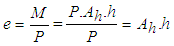 | (1) |
Where,e = eccentricity of applied loadP = vertical load applied on footingAh = horizontal seismic coefficienth = height of applied horizontal load from base of the footingM = bending moment generated on footing due to horizontal loading 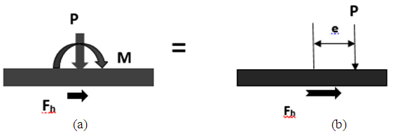 | Figure 3. (a): All loads applied on strip footing (b) Eccentricity of vertical load |
Due to this, base contact pressures will be as shown in Figs. 4(a) and 4(b).(i) Pressure distribution when e ≤ B/6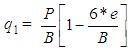 | (2) |
 | (3) |
 | (4) |
 | Figure 4(a). Pressure distribution when e ≤ B/6 |
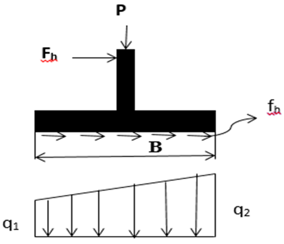
(ii) Pressure distribution when e > B/6 | (5) |
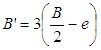 | (6) |
 | (7) |
 | Figure 4(b). Pressure distribution when e > B/6 |
Constitutive law of a soil define stress-strain behavior. Constitutive law of a soil defines stress-strain behavior. The behavior of soil over a wide range of stresses is nonlinear. Many constitutive relationships are available in the literature. Description of these is beyond the scope of the paper. KONDNER (1963) hyperbolic function as given in Eq (8a) or Eq (8b) has been used in the analysis.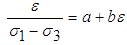 | (8a) |
Or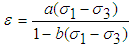 | (8b) |
Where, ε = Axial straina, b = Constant of hyperbolaσ1, σ3 = Major and minor principal stresses
3. Analyses
3.1. Assumptions
The analysis is based on the following assumptions:1) The soil mass is semi-infinite and isotropic medium.2) In the first instance, interference is considered between two fully flexible strip footings of equal width. Further both the footings are considered to have equal loads. 3) The contact pressure distribution is considered as shown in Fig. 4(a) and Fig. 4(b).4) The stresses in each layer have been computed using Boussinesq’s theory as the stress equations for various types of loads are available.5) The strains have been computed from the known stress condition using constitutive law of soil.6) The whole soil mass supporting the footings has been divided into a large number of thin horizontal strips up to a depth as shown in Fig.5. | Figure 5. Two same size and same loaded footing in seismic region |
3.2. Procedure
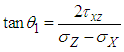
The procedure adopted for the evaluation of the settlement and tilt of an interfering footing, is described in the following steps:Step 1:Due to the contact pressure distribution (q1, q2 or q from Eqs. 2, 3 or 7) and horizontal stresses (fh from Eq. 4) at the interface of footing bases and supporting soil media induces stresses in the soil. Step 2:Evaluation of stresses (σz, σx, τxz) in each layer of the soil mass (as shown in Fig .5) at vertical sections due to existing and interfering footing stresses have been obtained separately using theories of elasticity and then added. Superimposing of stresses due to the two footings have been done to get the total stresses. After calculating these stresses principal stresses were calculated using Mohar’s Coulomb equations and their directions with respect to the vertical are determined, using following equations: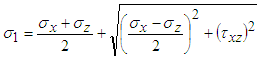 | (9) |
 | (10) |
 | (11) |
 | (12) |
Where, σx = Normal stress in x-direction σ z = Normal stress in x-directionτxz = Shear stress in xz plane Where θ1 and θ3 are the directions of the principal strains with respect to the vertical axis.Step 3:Strip footings representing the plane strain condition, after simplifying the expressions for principal strains, are given by: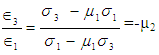 | (13) |
Where  = Major and minor principal strains respectively.
 | (14) |
 = Poison’s ratioStep 4:The strain in the direction of major principal stress is computed from constitutive relations as given below:
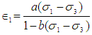 | (15) |
The strain in the minor principal stress direction is given by, | (16) |
Step 5:Soil stratum below footing base is considered up to 4 times width of footing. This depth is divided into equal parts of B/8 depth to calculate settlement at a point below footings. Strains have to be calculated at these 32 points as shown in fig (5). After knowing strain at each point these were added to find the values of total strain at the base of footing. The strain in the vertical direction (εz) for each layer was computed using the following expression: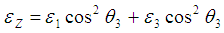 | (17) |
Step 6:The vertical settlement (Se) of any layer is computed by multiplying the strain  with the thickness of each layer δz:
 | (18) |
The total settlement (St) along any vertical section is computed by numerically integrating the expression: | (19) |
Step 7: Settlement pattern of a flexible interfering footing will be as shown in Fig. 6(a). Interfering rigid footing will settle as shown in Fig. (b).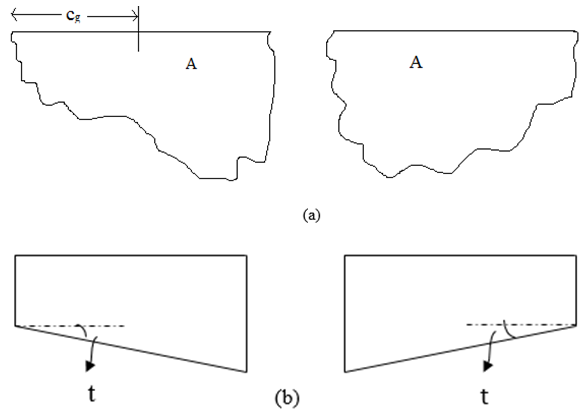 | Figure 6. Settlement patterns of interfering (a) flexible footing (b) rigid footing |
Following concept has been utilized for obtaining Smax, Smin and tilt of an interfering footing. Formulas for relation between settlement of rigid and flexible footing-: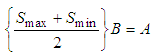 | (20) |
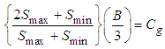 | (21) |
 | (22) |
A =Area of settlement diagram of flexible footing Fig. 6(a)Cg = Distance of resultant settlement diagram from left edge the footing Since the values of A and Cg may be obtained by numerical procedures, values of Smax, Smin and t were obtained by solving Eqs. 20, 21 and 22.Step 8:In seismic case baring pressure vs tilt, bearing pressure vs smax are drawn for different combination for interfering footing by repeating step 1 to 8.Bearing capacity ratio (BCR) is defined as below: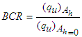 | (23) |
Where, (qu)Ah = Ultimate bearing capacity for seismic load (qu)Ah=0 = Ultimate bearing capacity for static load
4. Results and Discussion
4.1. Interfering Footing for Static Loading
Using the above analysis, section distance-settlement and pressure-maximum settlement characteristics of a strip footing have been obtained for the following parameters:Hyperbolic Constitutive laws parameters: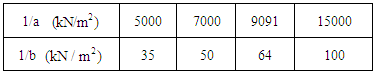 Section distance varies from -0.5m to 0.5m with interval of 0.1m.Pressure Intensity, q: 5 to 120 (Depending on the values of 1/a and 1/b).For illustration, for 1/a =15000; 1/b =100 and B=1.0m, stresses of equally spaced nine points of the base were obtained by using Boussinesq’s equation at each point for given pressure intensities. Stresses were first calculated due to existing footing and then stresses calculated due to interfering footing placed near to existing footing were also obtained for different pressure intensities and added them to found the settlement at these equally spaced points. Typical plots showing the settlement patterns for pressure intensities 25 and 50 are shown in Figs. 7(a) and 7(b) respectively. It is evident that these settlements of interfering (group) footing decreases with the increase in spacing up to a spacing of 3B and becomes almost equal to the settlement of an isolated footing. The increase in the settlement may be due to: (a) interfering footing acts as a surcharge for the existing footing and (b) at wider spacing no interference takes place and each footing acts as an individual (isolated) footing. It is also found from the Figs. 7(a) and 7(b) that if pressure intensity increases from 25kN/m2 to 50kN/m2 then the settlement of footing also increases because when load increases stresses generated below footing also increased hence results into more settlement.
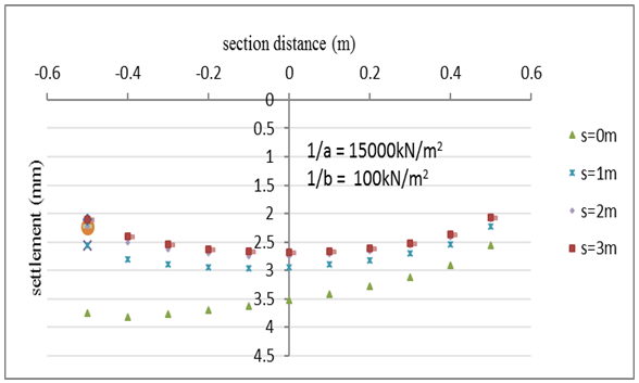 | Figure 7(a). Settlement pattern for p=25 kN/m2 due to interference |
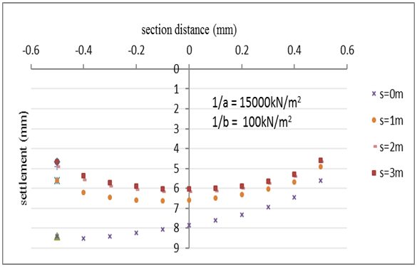 | Figure 7(b). Settlement pattern for p=50 kN/m2 due to interference |
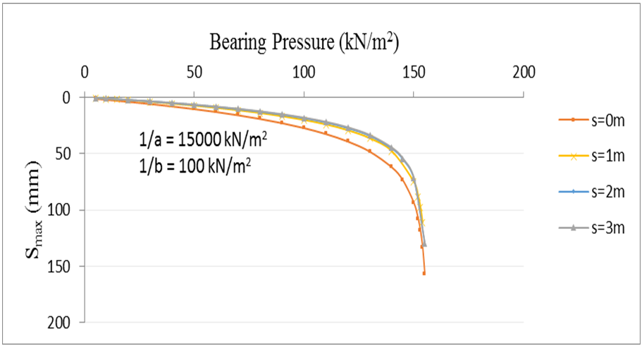
Typical bearing pressure versus maximum settlement curves for different combinations of 1/a and 1/b values are given in Figs 8(a), 8(b), 8(c) and 8(d) considering B=1.0m. It is evident from these figures that pressure- maximum settlement characteristics improves with the increase in 1/a and 1/b values. It was also concluded from these curves that maximum settlement of interfering (group) footing decreases with the increase in spacing up to a spacing of 3B and becomes almost equal to the average settlement of an isolated footing at spacing 3B. Where, average settlement is calculated by dividing the area of the settlement diagram of isolated footing with the width of footing.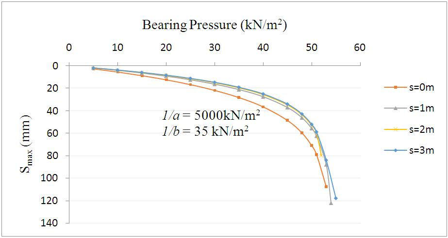 | Figure 8(a). Bearing Pressure vs Smax due to interference |
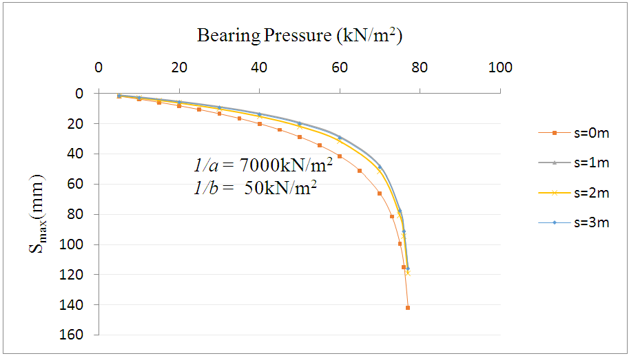 | Figure 8(b). Bearing Pressure vs Smax due to interference |
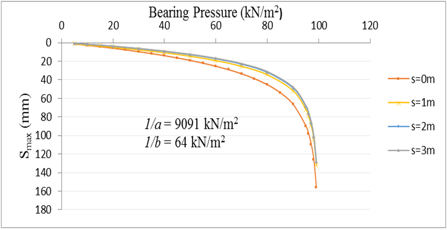 | Figure 8(c). Bearing Pressure vs Smax due to interference |
 | Figure 8(d). Bearing Pressure vs Smax due to interference |
4.2. Interfering Footing for Seismic Loading
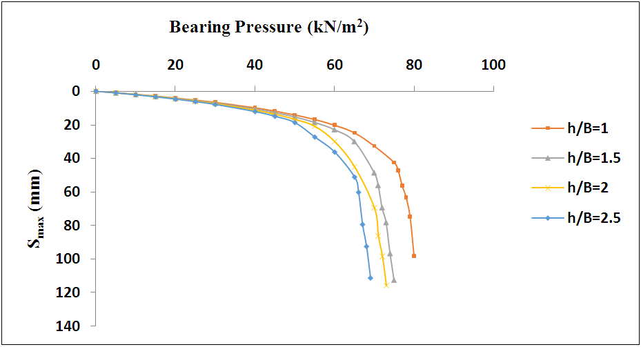
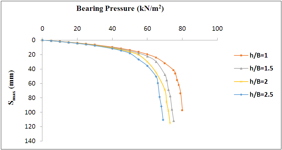
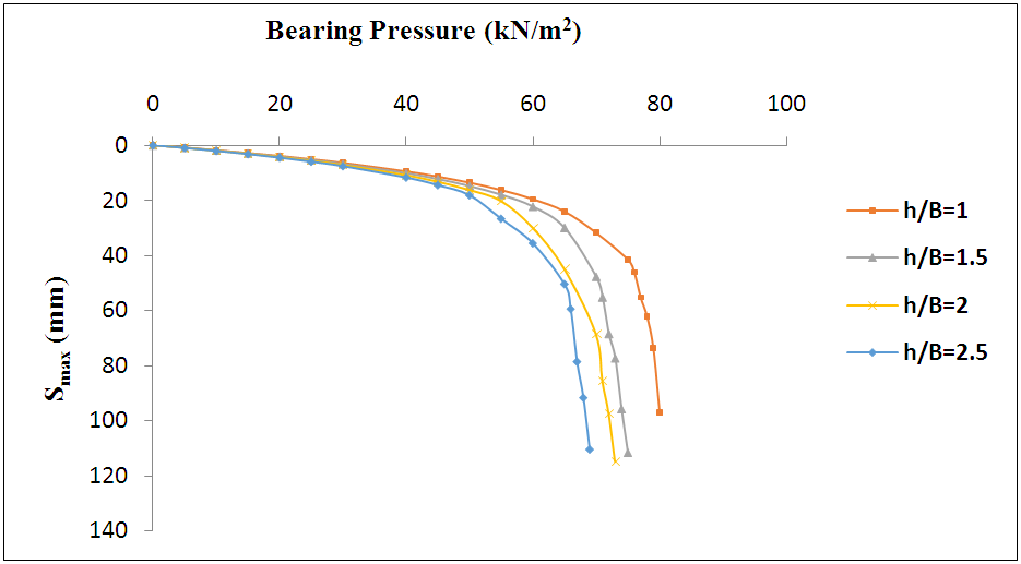
Using the above analysis, bearing pressure- maximum settlement, bearing pressure-tilt and bearing capacity ratio-height characteristics of a strip footing have been obtained for the following parameters:Spacing between two footings: 0 m, 1 m, 2 m, 3 mHeight, h (m): 1 m, 1.5 m, 2.0 m, 2.5 mHorizontal seismic coefficient (Ah): 0, 0.05, 0.1, 0.15The case of Ah =0 has discussed in previous section i.e. when seismic coefficient is zero the case becomes of static loading which has discussed.Figure 9(a) shows the variation of bearing pressure-maximum settlement curve for closely spaced 1 m footing on the saturated clay deposit with different values of h/B, S=0 m and Ah=0.05. To plot curve first stresses were found using different section loading as discussed in steps given above then whole procedure is same as static loading to find out maximum settlement. For different values of h/B stresses changed hence settlement also has changed. It can be seen that, the ultimate failure load becomes maximum at h/B = 2.5; irrespective of the magnitude of S/B. From Fig. 9(a) it can be also seen that settlement increases with bearing pressure.Similarly an investigation of Figures 9(c)-(d) indicates a significant effect on Smax of footing when the end to end spacing is varied from 0 to 3B, in the case of strip footing, 1 m for value of Ah=0.05. In Figures 9(a)-(d) Smax of interfering (group) footing increase with the increase in spacing up to a spacing of 3B and becomes almost equal to the maximum settlement of an isolated footing at spacing of 3B. These parameters of footing also changing with height as h increases Smax also increase.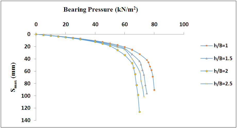 | Figure 9(a). Smax vs bearing pressure for Ah=.05, S=0 m |
 | Figure 9(b). Smax vs bearing pressure for Ah=.05, S=1 m |
 | Figure 9(c). Smax vs bearing pressure for Ah=.05, S=2 m |
 | Figure 9(d). Smax vs bearing pressure for Ah=.05, S=3 m |
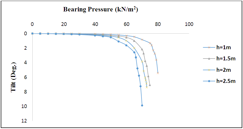
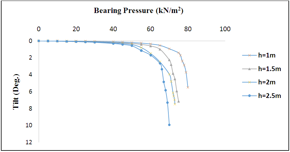
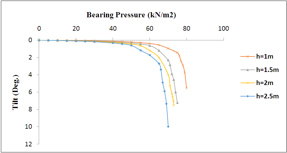
Figure 10(a) shows the variation of bearing pressure-tilt curve for closely spaced 1 m footing on the saturated clay deposit with different values of h, S=0 m and Ah=0.05. To find out tilt first maximum and minimum settlements were calculated using step 7 as given above. It can be seen that, the ultimate failure load becomes maximum at h = 2.5m; irrespective of the magnitude of S/B. From Fig. 10(a) it can be also seen that tilt increases with bearing pressure.Similarly an investigation of Figures 10(c)-(d) indicates a significant effect on tilt of footing when the end to end spacing is varied from 0 to 3B, in the case of strip footing, 1 m for value of Ah=0.05.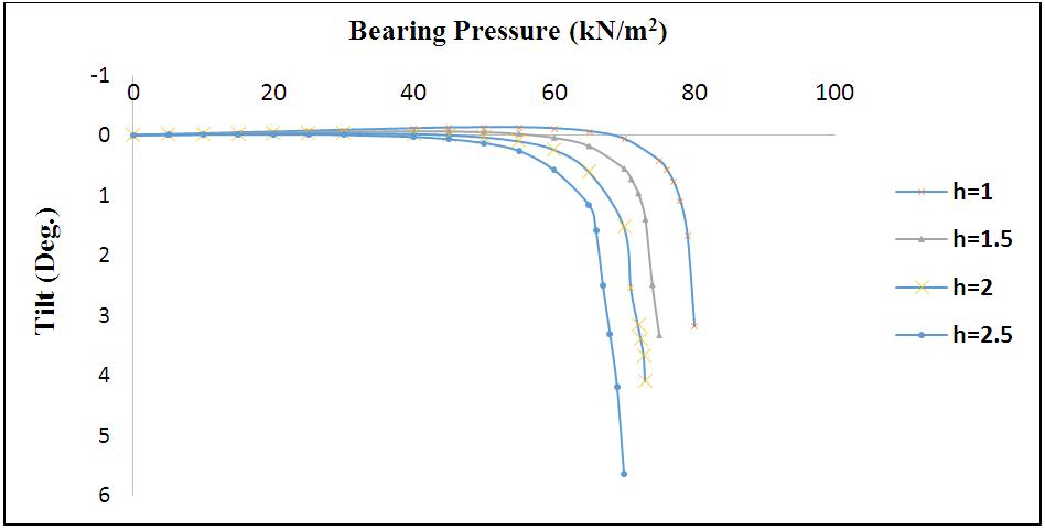 | Figure 10(a). Tilt vs bearing pressure for Ah=.05, S=0 m |
 | Figure 10(b). Tilt vs bearing pressure for Ah=.05, S=1 m |
 | Figure 10(c). Tilt vs bearing pressure for Ah=.05, S=2 m |
 | Figure 10(d). Tilt vs bearing pressure for Ah=.05, S=2 m |
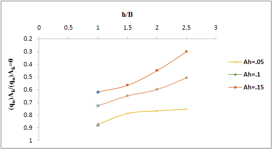
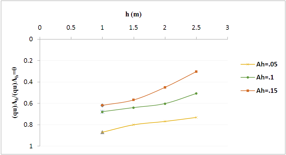
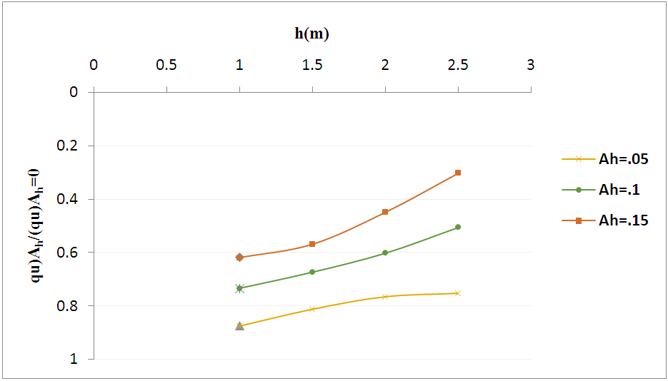
The results show that the value of horizontal coefficient (Ah) has the most effect on improvement of bearing capacity in respect to the other parameters. In this respect Figures 11(a), (b), (c) and (d) show the variation of BCR (ξ) versus h/B for different values of Ah and spacing.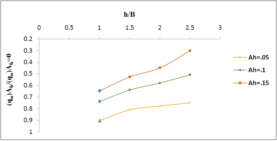 | Figure 11(a). Ultimate bearing capacities ratio vs h (m) for S=0 m |
 | Figure 11(b). Ultimate bearing capacities ratio vs h (m) for s=1 m |
 | Figure 11(c). Ultimate bearing capacities ratio vs h (m) for s=2 m |
 | Figure 11(d). Ultimate bearing capacities ratio vs h (m) for S=3 m |
The results indicate that the BCR (ξ) increases with decrease in the value of the Ah, And BCR (ξ) also increases with decrement in height of load applied.
4.3. Comparison of Analytical Results
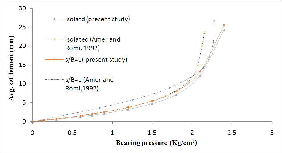 | Figure 12 |
5. Conclusions
5.1. Static Case
I. As spacing between footing increases, maximum settlement and tilt of an interfering decrease.II. Pressure-settlement characteristic of a footing improves with the decrease in the values of Kondner’s hyperbola parameters for static load case.III. Beyond the spacing equal to three times width of footing interference effect is insignificant.
5.2. Seismic Case
I. Maximum settlement and tilt of an interfering footing increases with increase in value of height (h) of seismic load (Fh).II. Bearing capacity ratio decreases with increase in value of horizontal seismic coefficient (Ah).
ACKNOWLEDGEMENTS
This is a part of the thesis work. The first author (RKY) is indebted to head, department of earthquake engineering, IIT Roorkee, for excellent computational facilities to carry out the work. Thanks to Mr. Tinku Biswas for his help during the work.
References
| [1] | Amir, A.A., (1992). "Interference effect on the behaviour of footings," thesis presented to the University of Roorkee, India, at Roorkee, in fulfilment of the requirements for the degree of Doctor of philosophy. |
| [2] | Amir, J.M. (1967). “Interaction of adjacent footing”. Proceedings 3rd Asian Regional Conference on soil Mechanics and Foundation Engg., Haifa, 1(5), 189-192. |
| [3] | Biswas T., Saran S., Shanker D. (2016). “Analysis of a Strip Footing Using Constitutive Law”, Geosciences p-ISSN: 2163-1697. |
| [4] | Dash, P.K. (1981). “Interference between surface footings on purely cohesive soil.” Indian geotechnical Journal, 11(4), 397-402. |
| [5] | Dembicki, E., Odrobinski, W., and Morzek, W. (1982). “Bearing capacity of sub soil under strip foundation”. Proceeding 10th International Conference on Soil Mechanics and foundation Engineering, Stockholm, 2, 91-94. |
| [6] | Hansen, J.B. (1963). “Discussion of hyperbolic stress-strain response of cohesive soil”. Geotech. Engrg., ASCE, (4), 241-242. |
| [7] | Konder, R.L. (1963). “Hyperbolic stress-strain response of cohesive soils”. J.Soil Mechanics and Foundation Engrg., ASCE, 89(1), 115-143. |
| [8] | Kouzer K. M., Kumar J. (2010). “Ultimate Bearing Capacity of a Footing Considering the Interference of an Existing Footing on Sand”, Geotech Geol Eng (2010) 28:457–470. |
| [9] | Mandel, J. (1965). “Plastic interference of continuous footing”. Proceedings 6th international conference on soil mechanics and foundation engineering, Montreal, 2, 127-131. |
| [10] | Meyerhof, G.G. (1963). ‘’Some Recent Research on the Bearing Capacity of Foundations”, Canadian Geotech. J. 1(1), 16-26. |
| [11] | Murthy, S.S.N. (1970). “Interference in surface footings on clear sand”. Proceeding Symposium on Shallow Foundations, Bombay, 1, 109-115. |
| [12] | Reddy Saibaba E., Borzooei Sina, Reddy Narasimha G. V (2012). “Interference between Adjacent Footings on Sand”, IJAERS/Vol. I/ Issue IV/July-Sept., 2012/95 98. |
| [13] | Saran, S. and Agarwal, V.C. (1974). “Interference of surface footings in sand”. Indian geotechnical Journal, 4(2), 129-139. |
| [14] | Shiba Reddy, A. and Mogaliah, G. (1976). “Interference between surface strip foundation on exhibiting anisotropy and non-homogeneity in cohesion”. J. Inst. of Engrs., 57, Part– CII, 7-31. |
| [15] | Stuart, J.G., (1962). ‘’Interference between Foundations with Special Reference to Surface Footings”, Geotechnique, 12(1), pp 15-23. |
| [16] | Terzaghi, K. (1943). “Theoretical Soil Mechanics”, John Wiley and Sons Inc. |
| [17] | Vesic, A.S. (1973). “Analysis of Ultimate Loads of Shallow Foundations”, J. Soil Mech. Found. Div., 99(1), 53. |
| [18] | West, J.M., and Stuart, J.G. (1965). “Oblique loading resulting from interference between surface footings on sand.” Proc. 6th Int. Conf. on Soil Mechanics and Foundation Engrg., Montreal, 2, 214-217. |

 Abstract
 Reference
 Full-Text PDF
 Full-text HTML