S. A. A Hosseini 1, M. Mohammadnejad 2, S. M Hoseini 2, R. Mikaeil 3, A. Tolooiyan 4
1Azad Islamic University of Shahrood, Iran
2School of Mining Engineering, Petroleum and Geophysics, Shahrood University of Technology, Iran
3Department of Mining and Metallurgical Engineering, Urmia University ofTechnology, Iran
4Geotechnical and Hydrogeological Engineering Research Group (GHERG), Monash University,Australia
Correspondence to: M. Mohammadnejad , School of Mining Engineering, Petroleum and Geophysics, Shahrood University of Technology, Iran.
| Email: |  |
Copyright © 2012 Scientific & Academic Publishing. All Rights Reserved.
Abstract
In the congested urban areas, tunnelling close to existing structures often occurs due to the lack of space. Consequently, tunnelling-induced ground movements may cause serious damage to the adjacent structures. Ground surface settlement caused by tunnel excavation varies in magnitude and trend depending on several factors such as tunnel geometry, ground conditions, etc. There are several empirical, semi-empirical equations and numerical methods available to estimateground surface settlement associated with excavation activities, however among these methods most of empirical and semi-empirical based methods do not simultaneously take all the relevant factors in the complex condition into account. In complex conditions, numerical methods can be used for resulting accurate predictions. In this paper, ground movement in a highly populated region of Iran’s capital city, Tehran, induced by excavation and construction of 7th line of Tehran subway has been investigated. It was aimed to analyse the ground displacements and surface settlement which hasbeen induced by tunnelling using Earth Pressure Balance-Shield Tunnel Boring Machine. The analysis was performed by Finite difference Method (FDM) using FLAC3D FDM package. Results from performed numerical analysis show good agreement with obtained results from analytical and empirical methods. In addition, effect of some important factors such as tunnel geometry and ground properties on ground surface settlement has been investigated. Obtained results indicate that ground surface settlement is more sensitive to tunnel geometry rather than height of tunnel placement.
Keywords:
Ground surface Settlement, Tehran Subway, Finite Difference Method, FLAC3D
Cite this paper:
S. A. A Hosseini , M. Mohammadnejad , S. M Hoseini , R. Mikaeil , A. Tolooiyan , "Numerical and Analytical Investigation of Ground Surface Settlement Due to Subway Excavation", Geosciences, Vol. 2 No. 6, 2012, pp. 185-191. doi: 10.5923/j.geo.20120206.06.
1. Introduction
Today one of the main issues of tunnelling activities in congested urban areas is interaction between tunnels and pre-existed urban structures. Ground surface settlement due to the subway excavation can simply affect sustainability and durability of pre-existed structures nearby the excavated area and hence it is one of the most important concerns in subway excavation process.Surface settlement caused by shallow underground excavation creates a concave shape subsidence basin which is typically shown in Figure 1[1]. As shown in this figure the coordinate system is defined where y denotes the distance from the tunnel centre line in the transverse direction, x is the coordinate in the longitudinal direction and z is the depth below ground level (bgl).Review of case history shows that the factors causing settlements can be categorised into four major categories (Figure 2): (1) tunnel geometry; (2) geological conditions; (3) shield operation factors; and (4) loading conditions. Loading condition consists of two type of load; 1) dead load and 2) live load. Dead loads are such as weight of overhead structures and overburden materials and live load are dynamic stresses due to crossing cars. Though, the live load can be ignored to simplify analysis in a reasonable way.Building damage due to settlements arising from tunnelling is predictable with a reasonable accuracy subject to the employed calculation technique. As a consequence the side-effects of settlement can be controlled through either variation of vertical/horizontal tunnel alignment, or partly by site specific measures such as underpinning, compensation grouting etc. Prediction of the magnitude and distribution of these movements is critically important in design process, as these predictions are used to estimate the tolerance of the neighbouring structures to the induced deformations. Several approaches have been presented by different researchers with the purpose of estimating maximum ground surface displacements along the tunnel axis and the surface area extension affected by deformation phenomena. The surface settlements can be estimated by using empirical or semi-empirical methods[2–8], analytical methods[9–15], and numerical methods[16–18]. Most of performed studies on this subject have been essentially performed based on geotechnical soil features and working peculiarities (e.g., excavation geometry and methodology). Also there are a number of uncertainties associated with predictions based on available methods, such as soilproperties variations, support system details and construction sequences. In practice, the observational method is commonly used to compare predicted performance with observed responses.In this paper, in addition to numerical investigation of ground surface settlement due to the excavation of 7th line of Tehran subway and associated station (O7 station), effect of neighbouring building weight on settlement has been evaluated. | Figure 1. Subsidence basin induced by a shallow tunnel excavation[1] |
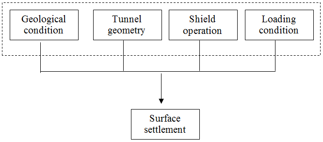 | Figure 2. Main factors which cause ground surface settlement(Modified from Suwansawat and Einstein, 2006) |
2. Technical Background
The 7th subway line is extended from North-West of Tehran towards the South-East of Tehran. Associated tunnels for this line are fully designed and planned to be excavated using Earth Pressure Balance Tunnel Boring Machine (EPB-TBM). The outer diameter of tunnel is 9.16m. The subsurface material in site area is formed from the quaternary aged alluvial fan deposits, which known as the Tehran Alluvial Formation. The thickness of these deposits has been reported as 60 m in the project area. The particle size of the alluvial deposits in the site area varies from clay to cobbles, with variable distribution, both in depth and horizontal extents. In this formation, there are alternated layers of coarse and fine grained soils, which could influence the design and construction of the proposed project. According to performed geotechnical and hydrogeological field investigations, the groundwater level is under the designed tunnel and the groundwater level variation has no considerable role in design and construction of the proposed subway line and associated station structures. The O7 station is one of the 7th line important underground stations which are located under a complex urban area. There are several buildings and slums in this region. Therefore, considering the underground works, environmental impact is an important issue in this excavation. To construct the subway station, a 60 m long narrow trench is vertically excavated to 18m bgl. This trench is used to transfer the workers, portable machinery and excavation devices to underground. From the base of the excavated trench, a 19.7 m length horizontal worker access tunnel is excavated normal to the trench axis and extended toward both sides (see Figure 3).Vertical boreholes are excavated from the end of horizontal access tunnel and lateral concrete bored piles are constructed inside the excavated boreholes, finally reinforced concrete pads connect each two bored pile together. Having both reinforced lateral concrete piles (as the wall) and a concrete pad (as the roof) will prepare a safe area for mass excavation which is required to construct the subway station. The mass excavation is performed layer by layer and total excavated depth consists of four layers of different materials as shown in Figure 3. Properties of these materials are presented in Table 1. | Figure 3. Geometry of O7 station and tunnel |
The tunnel will be supported by concrete segments. Mechanical characteristic of segment and shied is shown in Table 2.Furthermore, in tunnel construction by EPB machines the front pressure, injection pressure behind segments and pressure of jacks which pushes the shield forward are the main factors. Value of this pressure is shown in Table 3.| Table 1. Mechanical properties of soil |
| | Formation | Dry density | Cohesion | Friction angle | Elasticity modulus | Poisson’s ratio | | g/cm3 | kg/cm2 | Degree | MPa | - | | L1 | 1.9 | 0.2 | 38 | 100 | 0.27 | | L2 | 1.9 | 0.3 | 35 | 80 | 0.27 | | L3 | 1.9 | 0.3 | 30 | 50 | 0.3 | | L4 | 1.9 | 0.4 | 27 | 30 | 0.35 |
|
|
| Table 2. Mechanical characteristics of segment |
| | | Density | Elasticity modulus | Poisson’s ratio | | | kg/m3 | GPa | - | | Concrete segment | 2500 | 20 | 0.2 |
|
|
| Table 3. Different amounts of pressures witch effect excavation induced displacements |
| | Parameters | truest force | Face pressure | Grouting pressure | | Unit | kN | kN/m2 | kN/m2 | | Average pressure | 9000 | 55 | 150 |
|
|
In this paper, the ground surface settlement due to the construction of the subway tunnel and station, also effect of settlement on neighbouring building has been investigated using both empirical methods and numerical analysis.
3. Empirical and Analytical Methods to Estimate the Settlements
Several empirical, semi-empirical and analytical methods are developed to estimate the ground surface movements due to the underground excavation activities. These empirical and analytical methods are briefly described below.
3.1. The Peck Method
One of the most well-known empirical methods in this field is Peck method. This method is developed by Peck[2] and Schmidt[20] and well-being used in engineering practices. Using this method the vertical ground surface settlement along the tunnel axis can be estimated using a Gaussian distribution function shown as Eq. 1. | (1) |
Where w is magnitude of settlement at distance y from the tunnel centreline, wmax is maximum value of w over the tunnel centreline and iis distance from tunnel centreline to the point of inflexion on the settlement trough. The value of wmax can be calculated using volume of settlement trough per unit length of tunnel (Vs) where wmax=Vs/i√(2π)[3,5,21–23].
3.2. The Sagaseta Method
Sagaseta developed a closed form solution based method that evaluates the strain field in an initially isotropic and homogeneous incompressible soil[9,10,24]. In this solution the virtual-image technique is used to consider the presence of the top free surface. In this case, using the following equations, the vertical soil movement in the orthogonal plane to the tunnel axis w(y) and in the longitudinal plan w(x) are computable. | (2-1) |
 | (2-2) |
Where VS is the volume loss and Z0 is the tunnel-axis depth.This method simultaneously considers the effect from the ground loss,ε0, the ovalisation (ratio of the maximum value of the radial displacement of the tunnel wall, u, and the tunnel radius),ρ, and the volumetric compressibility,α[25]. The general expression of the vertical surface displacement field is given by: | (3) |
Where ε is the radial contraction equal to u0/a0, Z0the tunnel depth, u0 the uniform radial displacement, a0 the tunnel radius, y/ the distance from the tunnel centre scaled by the tunnel depth, α the exponent for volumetric compressibility and ρ the relative ovalisation that is equal toδ/ε, whereδis the ovalisation.
3.3. The Verruijt–Booker Method
Verruijt and Booker[11] develop an analytical solution for evaluating the ground movements dueto the tunnel excavation in a compressible soil. In fact, their method is a general form of Sagaseta’s solution and itcomputes the deep and surface vertical displacements and the horizontal displacements along a cross-section to the excavation direction. The Eq. (4) presents the closed form solution to estimate the vertical displacements: | (4) |
Whereεandδare parameters indicating the relative displacement of the tunnel surface, for uniform radial displacement case (ε) and the ovalisation case (δ), z1 = z - z0, z2 = z + z0,  ,
,  , m = (1 - 2v)-1, k = v(1 - v).Also, v is the soil Poisson’s ratio; a0and z0 are the tunnel radius and depth, respectively.The vertical field displacement at the ground surface estimates using the Eq. (5)
 | (5) |
By integrating Eq. (5) from -∞ to +∞, the uniform radial ground-loss value can be estimated.Also, total area of the settlement is obtained from Eq. (6): | (6) |
From which; | (7) |
Where,VS is the volume loss defined as the ratio of the settlement volume trough per meter and the excavated volume per unit advance.
3.4. The Loganathan–Poulos Method
This method is developed by improving the Verruijt and Booker method[12]. The improved method can takes the ground loss into account, considering it uniformly distributed along the tunnel wall.To consider the soil parameters, tunnelling method and support system, the authors introduced the gap parameter, g, which estimates the ground-loss value[26]. In particular, the equivalent un-drained ground loss,ε0, is defined as: | (8) |
Where g (the gap parameter) is the equivalent of a two-dimensional (2D) void formed around the tunnel. The parameter, g, can be estimated as the sum of three components[27]: | (9) |
Where,Gp is a physical gap representing the geometric clearance between the shield and the lining. For a circular tunnel, Gp=2λ+δ, where λ is the thickness of the tailpiece andδ is the clearance for erecting the lining[28]. The authors developed Eq. (10) to estimation the vertical surface displacement. The proposed equation considers only a short -term, un-drained condition and the ground deformation resulting from the long-term ovalisation of the tunnel lining is neglected. | (10) |
3.5. The Oteo Method
A semi-empirical method suggested by Oteo and et al. to estimation of the vertical surface displacements along the cross section of the tunnel axis. In this method the displacement is calculated by applying a modified Peck’s error curve to consider some additional tunnel and ground parameters: | (11) |
Where, i is the position of the inflexion point that estimated asi=a0η(1.05z0/2a0 – 0.42), ψ is an empirical parameter, E is the soil Young’s modulus, a0 is the tunnel radius, and v is the Poisson’s ratio
3.6. The Romo–Diaz Method
Using the finite element analysis Romo and Diaz[30] proposed an empirical equation to estimate the settlements along the tunnel axis as Eq. (12). | (12) |
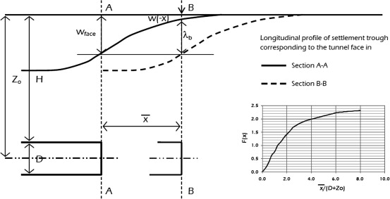 | Figure 4. Geometrical condition and values of the function F used in Romo–Diaz method[1] |
In this equationλb is the settlement at the section B–B (Figure 4) due to the passage of the tunnel face from the section A–A to the section B–B, Z0 is the tunnel-axis depth, H and D are tunnel overburden and tunnel diameter, respectively,  is the horizontal stress at the tunnel axis, p is the pressure acting at the excavation face, σfis the strength average value from the ground surface and the tunnel invert, εf is the average value of strain at the failure from the ground surface and the tunnel invert and ζa function related to the distance between the sections A–A and B–B (Figure 4). The value of w(-x) represents the settlements at a distance x from the tunnel face and it can be estimated as Eq. (13).
 | (13) |
4. Finite Difference Method
In this section, ground surface settlement has been simulated using FDM, with the use of Flac3D package. The FDM is perhaps the oldest numerical technique used to solve sets of differential equations, given initial values and/or boundary conditions. In FDM, every derivative in the set of governing equations is replaced directly by an algebraic expression written in terms of the field variables (e.g., stress or displacement) at discrete points in space; these variables are undefined within elements[31].This program simulates the behaviour of structures built of soil, rock or other materials that may undergo plastic flow when their yield limits are reached. Materials are represented by elements, or zones, which form a grid that is adjusted by the user to fit the shape of the object to be modelled.[32]. | Figure 5. Applied uniform pressure in model |
In this paper, the model geometry dimensions of 100 m × 90× 70 m were chosen. This model is constituted of 220950 zones and 227194 grid points, and it is confined by appropriate boundaries along the x, y and z, whereas the upper surface in z direction is free to move, as it corresponds to the effective ground surface and other side in x and y directions are fixed to prevention of any movement. Also, bottom boundary in z direction is fixed too. To model the weight of over-ground neighbouring structures, two 50000 KN uniform pressures have been applied on the two side of geometry surface (see Figure 5). Also, face and grouting pressures are imported to model. Figure 6 shows the designed FDM model.The mechanical behaviour of the soils is adopted to be elastic-plastic according to the Mohr-Coulomb yield criterion. The used mechanical properties are given in Table1. Also, the material properties that are used for modelling the shield and segments, as the elastic materials, are given in Table 2. 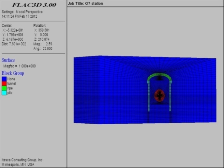 | Figure 6. Finite difference model of O7 station and tunnel |
5. Results and Discussion
As explained before, the objective of presented research work in this paper is simulation of ground surface settlement due to the construction of underground subway tunnel and station. Hence, first settlement due to the tunnelling is assessed using the numerical, empirical and analytical methods, then simulation of underground station construction is performed and associated ground settlement is calculated.Estimated maximum surface settlement due to the excavation of tunnel is shown in Table 4. Also the calculated settlement profile is show in Figure 7. As shown in this figure, the maximum settlement occurs just over the tunnel axis and vertical displacement decreases by increasing the horizontal distance from the tunnel axis. Moreover this figure shows that the Peck method predicts the upper value of ground surface settlement compare to other methods. Results of FDM analysis show excellent agreement with results from empirical methods especially Loganathan–Poulos method which shows only 9.5% difference.| Table 4. Maximum surface settlement assessment using different methods |
| | Method | FDM | Peck | Loganthan&Poulos | Verruijt& Booker | Sagaseta& Gonzales | | Settlement (cm) | 2.1 | 3.5 | 1.9 | 1.7 | 1.4 |
|
|
 | Figure 7. Predicted ground settlement due to tunnelling using various methods |
 | Figure 8. Numerically measured ground settlementdue to O7 station excavation |
In the next step, ground settlement due to station construction is investigated using numerical method. As explained in the prior section, the O7 station is constructed using underground construction method. The excavation process is modelled layer by layer downward. Figure 8 shows the ground settlement due to the excavation steps of the station. In step 1 the access trench is excavated, in step 2 the pile and concrete pad is located, in step 3 top head of station is excavated and finally in step 4 total remaining soil volume is excavated. As shown in Figure 7, the maximum settlement due to station excavation is 22 mm.Considering the threshold of building damage that has been developed by Rankin and shown in Table 5, the underground construction of the O7 station has no considerable effect on the existing over-ground buildings.| Table 5. Building damage category due to settlement |
| | Maximum building settlement (cm) | Damage type | Damage level | | 1 | Shallow damage is not probable | Neglect able | | 1-5 | Shallow damage has not structure effect | Low | | 5-7.5 | Shallow damage to building | Medium | | 7.5< | Structural damage to building | High |
|
|
6. Conclusions
Numerical and analytical modelling of Tehran 7th line subway tunnel has been performed using distinct element method in a commercial FDM package and four different empirical methods. Results of analysis revealed that predictions using both numerical and empirical solutions are in excellent agreement. Considering the marginal difference (9.5%) between calculated settlement using FDM and Loganthan-Poulos method and also serious difficulties and required skills which is associated with FDM analysis, empirical methods such as Loganthan-Poulos method is preferred than numerical analysis since they are cheaper and easier to use.To simulate the excavation of subway station, there is no available empirical method which can be used to model such a complicated geometry as designed for Tehran O7 subway station. In this case FDM is a great tool which can be used to simulate complicated underground excavation as presented in this paper. Also using FDM, it is possible to take the overburden stress due to the weight of over-ground neighbouring structures into account. Result of simulation of underground O7 station, confirmed that ground settlement due to excavation of the station, do not impose structural damage of over-ground buildings since the maximum ground settlement is less than 5 cm which is allowable range of ground displacement based on Rankin’s theory.
References
| [1] | M. Migliazza, M. Chiorboli, G.P. Giani, Comparison of analytical method, 3D finite element model with experimental subsidence measurements resulting from the extension of the Milan underground. Computers and Geotechnics 36, 2009. 113–124 |
| [2] | Peck RB. Deep excavation and tunneling in soft ground.State-of-the-art report. In Proc 7th intconf soil mechanics and found engineering, Mexico, 1969. pp 225–90. |
| [3] | Atkinson JH, Potts DM. Subsidence above shallow tunnels in soft ground. J. Geotech. Eng. Div. ASCE 1977; 103(GT4): 307–25. |
| [4] | Attewell PB, Woodman JP. Predicting the dynamics of ground settlements and its derivatives by tunneling in soil. Ground Eng. 1982; 15(8):13–22. |
| [5] | Mair RJ, Gunn MJ, O’Reilly MP. Ground movements around shallow tunnel in soft clay. 10th intconf on soil mechanics and foundation engineering, Stockholm, 1983. pp 323–8. |
| [6] | New BM, O’Reilly MP. Tunneling induced ground movements, predicting their magnitude and effects. Proc 4th conf on ground movements and structure, Cardiff, 1991. pp 671–97. |
| [7] | Einstein Z, El-Nahhas F, Thomson S. Strain field around a tunnel in stiff soil. Proc 10th intconf on soil mechanics and foundation engineering, vol. I, Balkema, 1981. pp 283–8. |
| [8] | Oteo C, Moya, JF. Estimation of the soil parameters of Madrid in relation to the tunnel construction. Proc 7th Euro conf. on soil mechanics and foundation engineering, vol. 3, Brighton, 1979. pp 239–47. |
| [9] | Sagaseta C. Analysis of undrained soil deformation due to ground loss. Géotechnique 1987;37(3):301–20. |
| [10] | Sagaseta C. Discussion on: Sagaseta C.: ‘‘Analysis of undrained soil deformation due to ground loss”. Author’s replay to B. Smhmidt. Géotechnique 1988;38(4):647–9. |
| [11] | Verruijt A, Booker JR. Surface settlements due to deformation of a tunnel in an elastic half plane. Géotechnique 1996;46(4):753–6. |
| [12] | Loganathan N, Poulos HG. Analytical prediction for tunneling-induced ground movements in clays. J. Geotech. Geoenviron. Eng. ASCE 1998;124(9):846–56. |
| [13] | Bobet A. Analytical solutions for shallow tunnels in saturated ground. J. Eng. Mech. ASCE 2001;127(12):1258–66. |
| [14] | Chou WI, Bobet A. Prediction of round deformations in shallow tunnels in clay. Tunnell. Underground Space Technol. 2002;17:3–19. |
| [15] | Park KH. Analytical solution for tunneling-induced ground movements in clays. Tunnell. Underground Space Technol. 2005; 20:249–61. |
| [16] | Suwansawat S, Einstein HH. Artificial neural network for predicting the maximum surface settlements caused by EPB shield tunneling. Tunnell. Underground Space Technol. 2006; 21:133–55. |
| [17] | Mroueh H, Shahrour I. A simplified 3D model for tunnel construction using tunnel boring machines. Tunnell Underground Space Technol, in press, doi: 10.1016/ j.tust. 2006.11.008. |
| [18] | Melis M, Medina L, Rodriguez JM. Prediction and analysis of subsidence induced by shield tunneling in the Madrid Metro extension. Can. Geotech. J. 2002;39:1273–87 |
| [19] | Schmidt B. Prediction of settlements due to tunneling in soil: three case histories. In: Proc 2nd rapid excavation tunneling conference, San Francisco, CA, 1969. pp 801–12. |
| [20] | Attewell PB, Farmer IW. Ground deformations resulting from shield tunneling in London Clay. Can. Geotech. J. 1974;11:380–95. |
| [21] | Clough GW, Schmidt B. Design and performance of excavation and tunnels in soft clay. In: Soft clay engineering. Amsterdam: Elsevier; 1981. p. 569–634. |
| [22] | O’Reilly MP, New BM. Settlements above tunnels in U.K. – their magnitude and prediction, Tunneling ’82, 1982. pp 173–181. |
| [23] | Uriel AO, Sagaseta C. Selection on design parameters for underground construction. Proc. of the 12th international congress on soil mechanics, Rio de Janeiro, vol. 9. Rotterdam: A.A. Balkema; 1989. p. 2521–51. |
| [24] | Gonzales C, Sagaseta C. Patterns of soil deformations around tunnels. Application to the extension of Madrid Metro. Comput. Geotech. 2001;28:445–68. |
| [25] | Rowe RK, Kack GJ. A theoretical examination of the settlements induced by tunneling: four case histories. Can. Geotech. J. 1982;20:299–314. |
| [26] | Lee K, Rowe RK, Lo KJ. Subsidence owing to tunneling. I: Estimating the gap parameter. Can. Geotech. J. 1992;29: 929–40. |
| [27] | Lo KY, Ng RMC, Rowe RK. Predicting settlement due to tunnelling in clays. In: Proc tunnelling in soil and rock, geotech III conference, ASCE, Reston, Va, 1984. pp 48–76. |
| [28] | Sagaseta C, Moya JF, Oteo C. Estimation of ground subsidence over urban tunnels. In: Proc 2nd conference on ground movement and structure, Cardiff, 1980. pp 331–44. |
| [29] | Romo MP, Diaz CM. Face stability and ground settlements in shield tunneling. In: Proc 10th intconf on soil mechanics and foundation engineering, vol. 1, Stockholm, 1981. pp 357–60. |
| [30] | Desai, C. S., and J. T. Christian. Numerical Methods in Geomechanics. New York: McGraw-Hill, 1977. |
| [31] | Itasca Consulting group. (2001). FLAC2D version4 user manual Lined Tunnel Construction in Saturated Ground. |
| [32] | SuchatveeSuwansawata, Herbert H. Einstein (2006). Artificial neural networks for predicting the maximum surface settlement caused by EPB shield tunneling, Tunnelling and Underground Space Technology 21, 133–150. |
 Abstract
 Reference
 Full-Text PDF
 Full-Text HTML