Odoh B. I 1, Onyeji Johnbosco 2, Utom A. U 2
1Department of Geological Sciences, Nnamdi Azikiwe University, Awka, Anambra State, Nigeria
2Onyeji, Johnbosco, Ebute-Metta, Lagos, P. O. Box 1369, Nigeria
Correspondence to: Utom A. U , Onyeji, Johnbosco, Ebute-Metta, Lagos, P. O. Box 1369, Nigeria.
| Email: |  |
Copyright © 2012 Scientific & Academic Publishing. All Rights Reserved.
Abstract
ISRC procedures were used to extrapolate petrophysical parameters away from the existing wells to other parts of the Amboy field. Two formations (Benin and Agbada Formations) are underlain in the study area. The massive Benin Sands outcrop at the surface with the base of fresh water sands at -7440ft., and the Agbada Formation was down to the total depth (-12975ft,). Four reservoir sand packages (C01, D01, D06 and D07) were mapped within the Agbada reservoir unit, but C01, D01 and D07 formed reservoirs of interest. The three sands (C01, D01 and D07) are of Miocene age, and formed a 3-way dip structural closure trapped against the up-thrown side of the NE - SW antithetic fault. The sands are relatively clean and well developed. Reservoir characterization specifics show; - porosity = 24 - 29.8%; hydrocarbon saturation. = 69 - 89%; permeability = 379 – 613 md and oil gravity ranges from 23 to 35 API (Normal Oil). The structural style of this area consists of growth faulting alongside other crestal relief faults. The D07 sand package is the largest reservoir observed in Amboy Field. Also, an increase in porosity, net/gross and hydrocarbon saturation were observed to lower the reservoir acoustic impedance of D07 sand package compared to the shallow reservoir sands.
Keywords:
Reservoir Characterization, Petrophysical Properties, Structural Map, Porosity, Permeability
1. Introduction
The Amboy field is one of the Niger Delta Oil fields, located on the north- eastern onshore part of the Nigerian’s Oil concessions. The field was discovered in April 1974 by AMB_1X exploratory well. The Field is down thrown to the E-W trending structure building fault. Hydrocarbon trapping mechanism is a 3-way up-dip structural closure against NE-SW striking antithetic fault. The Niger Delta area of Nigeria is situated in the Gulf of Guinea (Figure 1) and extends throughout the Niger Delta Province as defined by Klett et al. (1997). Doust and Omatsola (1990) noted that from the Eocene to the present, the delta has prograded southwestwards, forming depobelts of most active portion of each stage of the delta’ development. According to Kulke (1995), the Niger Delta contains only one identified petroleum system referred to as the Tertiary Niger Delta (Akata-Agbada) petroleum system. The maximum extent of the petroleum system coincides with the boundaries of the province (Opafunso, 2007) while the maximum extent of the system is defined by the area extent of the fields that contain known resources of 34.5 Billion Barrel of Oil (BBO) and 93.8 Trillion Cubic Feet of Gas Barrels of Oil (TCFG) (Petroconsultants, 1996b). | Figure 1. Index map of Nigeria and Cameroon. Map of the Niger Delta showing Province outline (maximum petroleum system); bounding structural features; minimum petroleum system as defined by oil and gas field centre points (data from Petroconsultants, 1996a); 200, 2000, 3000, and 4000 m bathymetric contours; and 2 and 4 km sediment thickness |
The Niger Delta province is ranked the twelfth richest petroleum resources with 2.2% of the world’s discovered oil and 1.4% of world’s discovered gas by the US Geological Survey’s World Energy Assessment (Klett et al., 1977). The province covers 300,000 km2 and includes the geologic extent of the Tertiary Niger Delta (Akata - Agbada) petroleum system. The tectonic framework of the continental margin along the West Coast of equatorial Africa is controlled by Cretaceous fracture zones expressed as trenches and ridges in the deep Atlantic. The fracture zone ridges subdivide the margin into individual basins and in Nigeria, form the boundary faults of the Cretaceous Benue-Abakaliki trough, which cuts far into the West African shield. Lehner and De Ruiter (1997) also noted that rifting started starting in the Late Jurassic and persisted into the Middle Cretaceous. After rifting ceased, gravity tectonism became the primary deformational process. Shale mobility induced internal deformational and occurred in response to two processes (Kulke, 1995): (1). Shale diapirs formed from loading of poorly compacted, over pressure, prodelta and delta-slope clay (Akata Formation) by the highest density delta front sands (Agbada Formation) and (2). Slope instability which occurred due to lack of lateral, basinward, support for the undercompacted delta-slope clays (Akata Formation). For any given depobelt, gravity tectonics, were completed before the deposition of the Benin Formation and are expressed in complex structures, including shale diapirs, roll-over anticlines, collapsed growth fault crest, back – to – back features and steeply dipping, closely spaced flank faults (Evamy et al 1978; Xiao and Suppe, 1992). These faults mostly of offset different parts of the Agbada Formation flatten into detachment planes near the top of the Agbada Formation.Three main formations have been recognized in the subsurface of the Niger Delta (Frankl and Cordy, 1967; Short and Stauble, 1967; Weber and Daukoro, 1975; Avbovbo, 1978; Tuttle et al., 1999). These Formations were deposited in the continental transitional and marine environments, respectively; together they form a thick, overall progradational passive margin wedge. The Akata Formation is the basal unit composed of marine shales believed to be the source rock within the basin. The Agbada Formation is made up of alternating sandstone, siltstone and shale sequences that constitute the petroleum reservoir of the basin. On the other hand, the Benin Formation largely consists of non-marine sands with a few shaly intercalations.In this study, Integrated Seismic Reservoir Characteristization (ISRC) approach to seismic and wireline data was adopted for the prediction of lateral extent of the reservoir, mapping of some reservoir sands, determination of petrophysical parameters and the study of the structural style of the subsurface. Various methods have been developed for the application of seismic data to broader hydrocarbon exploration and development as well as decision making (Brown, 2004). It has also been noted that structural stratigraphic integration in seismic data interpretation can allow for the spatial correlation of the tectonostratigraphic sequences. According to Jon and Richard (2004), sometimes the estimates of reserves may be dependent on structural interpretation when fluid contacts located on depth structure maps are needed as inputs in volumetric analysis. The high-resolution data provided by ISRC processing allowed for the interpretation of the lithostratigraphical units (Benin and Agbada Formations) encountered in the field, and four reservoir sand packages (C01, D01 and D07) within the Agbada reservoir body.
2. Methodology
Migrated 3-D seismic data were used to delineate geophysical structure evidenced by continuous lateral reflection events. Surface seismic data with high-lateral resolution, but of low vertical- resolution, provided acoustic impedance data. The acoustic impedance and seismic wavelet were estimated from wireline data acquired in the existing well. Amplitude variation of the same reflections was interpreted in terms of lateral and vertical changes in petrophysical properties and lithologies for reservoir characterization. Well log data with higher-vertical resolution with respect to that of seismic data, but of very shallow lateral penetration provided petrophysical parameters in the rock formations adjacent to the borehole. The ISRC method provides processing steps which bring the two sets of measurements to common physical base and to a common time/depth domain. The first step involved delineating the reservoir sands and saturating fluids in terms of standard petrophysical parameters (well log interpretation). This step aided in the interpretation of vertical - resolution of the field. The interpretation and correlation of different lithologies from the well logs were carefully carried out, noting and picking areas of sand and shale development from gamma ray and resistivity logs. The depth boundaries of such compartments were transformed into time domain to provide reference markers to the seismic data. Subsequently, seismic time horizons were tied to the markers and laterally followed across the complete seismic cube to reconstruct the local structural traps and stratigraphic embedding. Petrophysical parameters were also determined from individual logs. The values obtained were slotted into the appropriate Archie’s equation to obtain the required petrophysical data, using computer logic. Fluid types and contacts were determined based on resistivity and porosity logs (Tables 1 - 3). The second step involved the application of seismic, structural and stratigraphic interpretation techniques, after tying the log markers (formation tops) to the seismic time section. This method involves, the identification of prominent features such as major faults (i.e., fault interpretation), and the delineation / mapping of continuous seismic reflection events (i.e. horizon interpretation). To integrate the two sets of the measurements, velocity model were built with a combination of check shots of the control well and stacking velocity of the area for the conversion of Time-Depth using TDQ software. The model was used to generate the depth structure map of the interpreted horizons, contoured at 50ft interval using ZMAP application.
2.1. Data Set
The Amboy oilfield where the data set for the study was collected is owned and managed by Chevron Nigeria Limited. The precise location was not disclosed in line with current practices by petroleum industries in Nigeria. Nonetheless, the graphic description of the data set used for the study reported in this paper is shown in Figure 2. 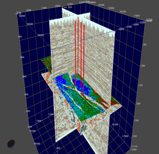 | Figure 2. 3D graphic view of the data set used for the ISRC processing reported in this paper. Wells are shown in red lines and an amplitude RMS extraction on top of a colour-coded time slice illustrating local structural embedding and areas of hydrocarbon prospects. Two oblique seismic cross-sections showing lateral and time extent of the seismic cube |
The seismic time horizon and the well locations shown in that Figure 2 define an approximately 550 km seismic cube acquired in an active hydrocarbon producing field. The cross-section of the migrated 3-D seismic data (dip and strike lines) that shows three mapped horizons, faults and the interpolated GR and RES logs are shown in Figure 3.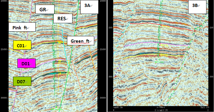 | Figure 3. A: - Seismic Dip line (L5944) cross- section showing displayed well log curves (gamma ray & resistivity), mapped horizons and interpreted faults and formation tops. 4B: - Strike line (T1608) cross-section illustrating lateral - resolution of 3D seismic data, fault intersections and horizon makers |
The correlated stratigraphic cross-section of the study area was illustrated in Figure 4 (well ABM_ 01 in the figure lacks some data and was not studied in detail). 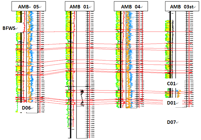 | Figure 4. Correlated Stratigraphic cross-section showing formation tops and bases, reservoir sands and fault cut in well 05 (D01) |
Figure 5 is time slice sampled at 2.5 ms showing the embedded structure in the study area. While figures 6A and 6B are the depth map of D07 sand superimposed on its RMS extracted amplitude to show structural conformity and the base map of the study area that illustrates well locations, fault polygons and an interpreted time horizon respectively. 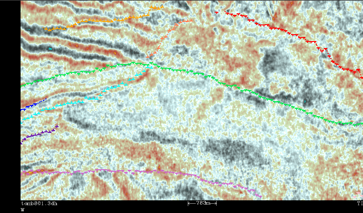 | Figure 5. Seismic time slice sampled at 2.5 ms showing the embedding structure in the study area |
3. Results and Discussion
3.1. Stratigraphy
Lithostratigraphic interpretation of the Amboy Field was done by the use of well logs; correlation of sandstone and shale bodies; and construction of subsurface cross-sections. Two lithostratigraphic units; - Benin and Agbada Formations were recognized in the wells studied (AMB_05, 01, 04, 03st). From the analysis of the well logs, the Benin Formation was recognized by low gamma ray count and high resisitivity reading of fresh water. The massive Benin Sands were encountered at the surface, with the base of fresh water sands (BFWS) at about -7440ft. It was observed that the upper part of the formation is sandier than the lower part. The base of this formation was determined in all the wells by the first remarkable changes in the well logs responses. These changes include; increase in the number of intervals with high gamma ray readings and high resistivity readings; the sand on the top of the first thick shale bed interval was identified as the BFWS based on the above mentioned changes (Figure 4). The sands were unconsolidated, fine to medium grained with interbedded clay to shale bed and lignite beds. The Benin Formation has been interpreted to have been deposited in shallow water depositional environment (Short and Stauble, 1967; Ekweozor and Daukoru, 1984). The base of Benin Formation was determined in wells 05, 01, 04 and 03 as -7440ft. Agbada Formation was down to the total depth. An increase in the alternations of sandstone and shale were recognized on the formation; suggesting a decrease in the sand/shale ratio; and mark the appearance of the paralic Agbada Formation. Also, at the upper part of the Agbada Formation, distinctive shaly bodies were identified below the BFWS (Figure 4). These shaly bodies were delineated by peculiar log signatures and they are present in all the wells. The shale was correlated across the entire field from E-W. The thickness of the shale ranges from 64 to 96 ft. This transitional paralic interval represents part of the Agbada Formation; and a transition from continental Benin Formation to Agbada Formation. Four reservoirs sands (C01, D01, D06 and D07) were also recognized (Table 1). The presence of interbedded shales provided the top seals against vertical migration of hydrocarbon. Hydrocarbon bearing sands are mainly found within the Miocene package in the Amboy field.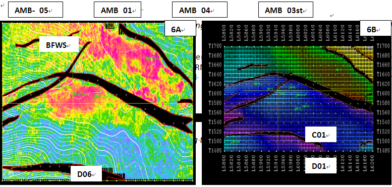 | Figure 6. A: - Depth map of D07 reservoir superimposed on its RMS extracted amplitude to show structural conformity. 6B: - Base map of the study area showing well locations, fault polygons, interpreted time horizon (C01; shallow horizon) and displayed Dip line 5944 and Strike line 1608 |
3.2. Structure
Amboy Field is a simple faulted anticlinal structure. The structural style in this area consists of growth faulting alongside with other crustal relief faults (Figures 3 and 5). The synsedimentary growth faults activated at the delta front retards the advancement of the sandy Benin Formation. The down thrown part becomes the new focus of Agbada paralic facies deposition until subsidence stabilizes; by then a maximum thickness of Agbada Formation has been deposited (Ekweozor and Daukoru, 1984). The prominent structural features recognized in this field include: rollover anticlinal ridges (C01, D01 and D07) and the associated synclinal features (Figures 7A – 7C). C01/AMB_04; - Well developed hydrocarbon reservoir with clean sand, coarsing upwards; It has good correlative and lateral continuity across the field (Figure 7A). D01/AMB_04: - Lacks good correlative and lateral continuity across the field, since it is faulted out in AMB_05; well-developed reservoir with clean sand and some shaly matrix, fairly consolidated and the sand is fine to medium grained (Figure 7B). D07/AMB_05: - Deposited in a wave dominated deltaic front marine environment. It has very good correlative and continuity across the field. It is the largest known reservoir in the field (Figure 7C); well developed hydrocarbon reservoir with clean sand at the upper part and some shale matrix intercalations at the lower interval. The sand is fine to medium grained and fairly to poorly consolidated. The three sands (C01, D01 and D07), all lie within the Miocene and are all 3-way up-dip structural closure trapped against the up thrown side of the NE-SW trending antithetic fault.| Table 1. Identified Gross Sand, Net Sand and Pay within the Amboy reservoir bodies |
| | Well Nos. | Sand Bodies | Zone Top | Zone Base | Gross Sand | Net Sand | Net Pay | Net/Gross | | AMB_05 | D06 | 10851 | 10889 | 38 | 32 | 30 | 0.84 | | | D07 | 10956 | 11067 | 102 | 90 | 87 | 0.75 | | AMB_04 | C01 | 9516 | 9552 | 36 | 32 | 26 | 0.88 | | | D01 | 10498 | 10588 | 90 | 32 | 26 | 0.82 | | | D07 | 11076 | 11202 | 126 | 88 | 62 | 0.69 | | AMB_03st | D07 | 1150.1 | 11566.5 | 65.4 | 53.4 | 26.7 | 0.81 |
|
|
| Table 2. Average porosity distribution in Amboy Field |
| | Zone Name | | Well Nos. | | | | AMB_05 | AMB_04 | AMB_03ST | | C01 | Nil | 29.80% | Nil | | D01 | FT cut | 26.10% | Nil | | D06 | 24.00% | Nil | Nil | | D07 | 25.00% | 25.10% | 15.30% |
|
|
Table 3. The hydrocarbon saturation distribution in the Amboy Field
 |
| |
|
 | Figure 7. A: - Depth Structure map of Yellow_Horizon (near C01 top) showing C01 reservoir sand with its fluid contents & contacts; Oil (red) and Water (blue). 7B:- Depth Structure map of Pink_Horizon (near D01 top) showing D01 reservoir sand with its fluid contents &contacts; gas (top), oil (middle) and Water (base). 7C:- Depth Structure map of Green _sand_Horizon (near D07 top) showing D07 reservoir sand with its fluid contents & contacts; oil (middle) and Water (base) |
3.3. Reservoir Characteristics
Three out of the four potential reservoirs recognized in the field were an area of interest; among them are C01_sand, D01_sand, and D07_sand. Wireline petrophysical parameters were laterally extrapolated from the existing control wells (AMB_ 05, 04, 03st) to other parts of the field using migrated 3-D seismic data. This process provides a very good result on reservoir properties necessary for reservoir characterizations. The porosities of the reservoirs range from 25-29.8%, Vertical and slight lateral variations were observed in the porosity values of the field (Table 2). This was suggested to be as a result of sedimentation processes and the age of the sediments. Hydrocarbon saturation values changes slightly from E-W and decreases down the depth; depicting that at greater depth hydrocarbon saturations declines (Tables 3). Also, increase in porosity, net/gross and hydrocarbon saturation were observed to lower the reservoir acoustic impedance of D07 reservoir sand in well AMB_05 compared to the shallow reservoir sands tested by the same well; this could be attributed to the lithology. Production depth varies from 9516 ft to 11200 ft in the field. C01 / AMB_04: - Gross thickness = 36 ft; Net thickness = 27 -32 ft; Average porosity = 29.8 %; Average Hydrocarbon Saturation = 82 %; Average Permeability = 379md; Oil Gravity = 23 API; 3 Reserves = 4.6 Million Barrel of Oil. D01 / AMB_04: - Gross thickness = 90ft; Net thickness = 32-74 ft; Average porosity = 26.1%; Average Hydrocarbon Saturation. Sat. – 69.2%; Average Permeability = 232 md; Oil Gravity = 33 API; 3 Reserves = 3.9 Million Barrels of Oil. D07 / AMB_05: - Gross thickness = 90 ft; Net Pay = 87ft; Average porosity = 25%; Average Hydrocarbon Saturation = 89.1%; Average Permeability = 613 md; Oil Gravity = 35 API; 2 Reserves = 16.5 Million Barrel of Oil.
4. Conclusions
ISRC method provides an excellent process of integrating well log data with the high –lateral resolution of seismic data needed for reservoir development and management. This procedure worked very well by estimating a joint Probability Density Function (PDF) that defines the physical relationship between seismic measurements and petrophysical parameters. Three Miocene horizons have been mapped and better correlated across the major faults and well locations. The three main reservoirs recognized in the field have very good porosities (25 - 29.8 %), very good hydrocarbon saturation (69 – 89 %), good permeability (379 – 613 md) and good oil gravity (23 - 35 API). The oil gravity range of this field show that the oil has undergone less biodegradation as a result of microbial influence; therefore, the oil is referred to as Normal Oil. This study may have a significant impact on the reservoir characterization of the Amboy oilfield. Moreover, migrated 4-D seismic data is recommended to enhance the reservoir characterization of this field.
ACKNOWLEDGEMENTS
We would like to express our gratitude to Tad Schirmer, the manager Earth Science Services Division CNL and Udegbunam Felix for giving us the opportunity to work with his wonderful group. Also our warmest thanks go to the management of ChevronTexaco Nigeria Limited for permission to use their 3-D seismic and well-log data set from exploration workstation Lekki-Lagos. Many thanks to Femi Esan and Mrs. T.O. Ogun for their moral support.
References
| [1] | Avbovbo, A.A. 1978. Tertiary lithostratigraphy of the Niger Delta. American Association of Petroleum Geologists Bulletin. 62, 295-307 |
| [2] | Brown, A. R. 2004. Interpretation of three-dimensional seismic data. American Association of |
| [3] | Petroleum Geologists, Memoir 42 SEG Investigations in Geophysics. 9, 12-99 |
| [4] | Doust, D.M. and Omatsola, E. 1990. Niger Delta. In Divergent/Passive Margin Basins, J.D. Edwards and P.A. Santogrossi, editors. AAPG Memoir 48. American Association of Petroleum Geologists, Tulsa, USA, pp. 239 – 248 |
| [5] | Ekweozor, C.M. and Daukoru, E.M. 1984. Petroleum source bed evaluation of Tertiary Niger Delta – reply. American Association of Petroleum Geologists Bulletin. 68, 390 – 394 |
| [6] | Evamy, B.D., Haremboure, J., Kamerling, P., Knaap, W.A., Molloy, F.A. and Rowlands, P.H. 1978. Hydrocarbon habitat of Tertiary Niger Delta. American Association of Petroleum Geologists Bulletin. 62, 277-298 |
| [7] | Frankl, E. J. and Cordy, E. A. 1967. The Niger Delta oil province recent development onshore and offshore: Proceedings of the 7th World Petroleum Congress, Mexico City, 1967, 195-209 |
| [8] | Jon G. and Richard S. 2004. Petroleum Geoscience. Blackwell Publishing, USA. pp. 54 – 112 |
| [9] | Klett, T.R., Ahlbrandt, T.S., Schmoker, J.W. and Dolton, J.L. 1997. Ranking of the world’s oil and gas provinces by known petroleum volumes. U.S. Geological Survey Open-file Report-97-463, CD-ROM. pp. 56 – 58 |
| [10] | Kulke, H. 1995. Nigeria. In Regional Petroleum Geology of the World. Part II: Africa, America, Australia and Antarctica, H. Kulke, editor. Gebrüder Borntraeger, Berlin, Germany, pp. 143-172 |
| [11] | Lehner, P. and De Ruiter, P.A.C. 1977. Structural history of Atlantic Margin of Africa. American Association of Petroleum Geologists Bulletin. 61, 961 – 981 |
| [12] | afunso, Z.O. 2007. 3D formation evaluation of an oilfield in the Niger Delta area of Nigeria using Schlumberger Petrel Workflow Tool. Journal of Engineering and Applied Sciences. 2, 1611 – 1660 |
| [13] | Petroconsultants, 1996b. PetroWorld 21: Houston, Texas, Petroconsultants, Inc., [database available from Petroconsultants, Inc., P.O. Box 740619, Houston, TX 77274-0619] |
| [14] | Short, K.C. and Stauble, A.I. 1967. Outline of Geology of Niger Delta. American Association of Petroleum Geologists Bulletin. 51, 761-779 |
| [15] | Tuttle, L. W. M., Charpentier, R. R. and Brownfield, E. M. 1999. The Niger Delta petroleum system: Niger Delta Province, Nigeria, Cameroon and Equatorial Guinea, Africa. U.S. Geological Survey Open-File Report 99-50-H, Denver, Colorado, p.70 |
| [16] | Weber, K. J. and Daukoru, E.M. 1975. Petroleum geology of the Niger Delta. Proceedings of the 9th World Petroleum Congress, volume 2, Geology. Applied Science Publishers Ltd., London, pp. 210-221 |
| [17] | Xiao, H. and Suppe, J. 1992. Origin of rollover. American Association of Petroleum Geologists Bulletin. 76, 509 – 529 |
 Abstract
 Reference
 Full-Text PDF
 Full-Text HTML