-
Paper Information
- Next Paper
- Previous Paper
- Paper Submission
-
Journal Information
- About This Journal
- Editorial Board
- Current Issue
- Archive
- Author Guidelines
- Contact Us
Frontiers in Science
p-ISSN: 2166-6083 e-ISSN: 2166-6113
2012; 2(6): 187-191
doi: 10.5923/j.fs.20120206.09
MREHS: Implementaion of MPPT-based RF Energy Harvesting System for Electrical Appliances
 Abstract
 Reference
 Full-Text PDF
 Full-Text HTML
E. Jebamalar Leavline1, D. Asir Antony Gnana Singh2
1Department of Electronics and Communication Engineering, Anna University of Technology, Tiruchirappalli, 620024, India
2Department of Computer Science and Engineering, M.I.E.T. Engineering College, Tiruchirappalli, 620 007, India
Correspondence to: E. Jebamalar Leavline, Department of Electronics and Communication Engineering, Anna University of Technology, Tiruchirappalli, 620024, India.
| Email: |  |
Copyright © 2012 Scientific & Academic Publishing. All Rights Reserved.
Power crisis is a major hurdle to the progress of the industrial world. Many new approaches for energy harvesting are under consideration, but their success in different environments is still to be seen. Among others, RF energy has gained tremendous attention as eco-friendly power source. In this work, we present a model of RF energy harvesting system based on RFID technology with maximum power point tracking (MPPT). Using the MPPT principle of Perturbation and Observation (P&O), an MPPT-based RF energy harvesting system (MREHS) was constructed for energy harvesting. In this approach, the controller adjusts the voltage by a small amount from the array and measures power; if the power increases, further adjustments in that direction are made until power no longer increases. This approach, also referred to as hill-climbing method, depends on the rise of the curve of power against voltage below the maximum power point and the fall above that point. This MPPT-based power model is remarkable because of its ease of implementation and improvement of top-level efficiency. Several functional units and circuitries are implemented to stimulate the system. An outstanding feature of this system is non-linear, scalable implementation with consistent operating conditions and improved output gained by optimized design. The performance of the model is evaluated by experimenting with light loads, whose results are very close to simulation results.
Keywords: RF Energy Harvesting, Maximum Power Point Tracking, Energy Storage
Cite this paper: E. Jebamalar Leavline, D. Asir Antony Gnana Singh, "MREHS: Implementaion of MPPT-based RF Energy Harvesting System for Electrical Appliances", Frontiers in Science, Vol. 2 No. 6, 2012, pp. 187-191. doi: 10.5923/j.fs.20120206.09.
Article Outline
1. Introduction
- Wireless power transmission via RF radiation, both near- and far-field, has invited great interest for over a decade. In near-field, the powering device is small in relation to the wavelength and is coupled with the source by inductive or capacitive coupling, making the device sensitive to its relative position. Far-field powering involves plane wave propagation between antennas at longer range without line of sight and is less sensitive to the orientation and position of the transmitting antenna[1-5].Far-field powering at low incident power densities (<10 W/cm) is addressed in[6]. Unlike in radio frequency identification (RFID) devices, the powering is independent of signal transmission and is done at different time scales, power levels and ranges. Few applications use this technique for harvesting energy at sub-milliwatt power levels. By optimizing the interface between the rectifying antenna and typical low-power sensor loads, high overall efficiency could be achieved[6].The primary application areas of RF energy harvesting are based on the RF field power density, total rectifier and filter output power and by the dynamic nature (both spatial and temporal) of the RF energy being harvested[7]. The main aim of our work was to develop a system that harvests RF power effectively andstores it for driving light loads. That is, our system acts as one of the member of the cellular network to harvest the RF power.The reminder of the paper is organized as follows. In section 2, a review of previous related works is presented. In section 3, MMPT is described. In section 4, the proposed experimental setup for RF energy harvesting is discussed. In section 5, the experimental results are provided. The concluding remarks are presented in section 6.
2. Related work
- In recent years, RFID technology has been widely employed in high-speed assemblage of finished goods and materials. Unlike barcode technology, RFID enables identification from a distance, and it does so without requiring a line of sight. RFID tags support a larger set of UIDs than do barcodes, and additional information including manufacturer details, product type, and even measurement of environmental factors such as temperature are possible to be incorporated in them[8]. RFID systems with different combinations of tags, readers, frequencies and levels of tagging are realizable. The cost and potential benefits of each system vary widely. RFID, which is an automatic identification and data capture technology, is composed of three elements: a tag formed by a chip connected with an antenna, a reader that emits radio signals and receives responses from tags, and a middleware that bridges RFID hardware with applications[9].The categories of RFID tags are: 1) active tag, which has a battery that supplies power to all functions; 2) semi-passive tag, which has a battery used only to power the tag IC but not for communication; and 3) passive tag, which has no battery on it. The fact that passive tags need no power supply makes it much cost-effective and long-lasting than active tags[10].RFID devices provide a real-time communication with numerous distant objects at a time through radio waves, with increased accuracy, efficiency and processing speed. These can help save on storage, handling and distribution costs and improve revenues[8, 9]. The application of RFID technology in data processing and microelectronics has paved way for remarkable developments. Components produced with this technology are becoming smaller and smaller, less costly, but are highly effective. The energy needed to power the tag IC is obtained during reader interrogation periods. Maximum power transfer efficiency from the reader to the tag has to be ensured for maximum read range. Mutual coupling between the reader and the tag decides the amount of power harvested at the tag. Mutual coupling can be considered as a variable load at the reader. This load may, however, lead to mismatch and poor power transfer efficiency if a fixed impedance matching circuit was implemented at the reader. Matching networks have been proposed to overcome this challenge[10].
3. Maximum Power Point Tracking
- Tracking the maximum power point (MPP) of a photovoltaic (PV) array in a PV system is a necessity. Several methods have been proposed that vary in complexity, sensors required, convergence speed, cost, range of effectiveness, implementation hardware, popularity, and in other respects[11–15]. Among others, the following five techniques are widely used for MMPT.
3.1. Perturbation and Observation (P&O) Method
- It has a simple feedback structure and hence widely used. It functions by introducing increment or decrement in the output voltage and comparing the output power of PV with the previous perturbation. The operating voltage of the PV array is perturbed in a given direction, and the power drawn from the PV array is observed. An increment in power drawn indicates the operating point has moved toward the MPP. The operating voltage is further perturbed in the same direction. In contrast, a decrease in power drawn from the PV array indicates the operating point has moved away from the MPP, and therefore, the direction of the operating voltage perturbation must be reversed. At steady state, the operating point oscillates around the MPP, causing a loss in available energy[12–14].
3.2. Incremental Conduction Method
- This method is based on the incremental conduction algorithm and relies on monitoring the output voltage (V) and current (I) from the source and making a decision on the ratio of output (I/V) based on the calculation of incremental conduction. In this method, one will know the exact time when MPP has occurred and hence decide when to stop the perturbation. The incremental conduction algorithm is, however, more complex than the P&O method[12,14,15].
3.3. Current Control MPPT
- To track MPP, a partial differential equation (PDE) may be formulated subject to P = VI. The partial derivative of power under different illumination conditions is then derived. The solution for this PDE represents the value of current that ensures maximum power. The identification of optimum point is described in[14–16].
3.4. Voltage Control MPPT
- This method uses a similar approach as current control MPPT. The optimum voltage corresponding to the maximum power is expressed as a function of cell voltage at open circuit condition[14,15].
3.5. Fuzzy System-based MPPT
- Fuzzy systems can solve complex mathematical problems and are simple to design. The formulation of MPPT using fuzzy systems is described elsewhere[14,15].
4. Implementation of MREHS
- The construction of an MREHS, with different functional units such as RFID tag, receiver, amplifier, rectifier, regulator, storage device and load, is illustrated in Figure 1.
4.1. Functional Units in an MREHS
4.1.1. RFID Tag
- The RFID tag can operate in four different modes: (1) power-up mode, (2) addressing mode, (3) reading mode, and (iv) quiet mode[9, 17, 18].Power-up mode: A reader radiates RF power (866 MHz) in the direction of one (or many) transponder(s)/tag(s). The power captured by the transponders’ antenna is rectified, which then energizes the circuits. At the same time, power-on-reset (POR) occurs and that turns the transponders to the addressing mode.
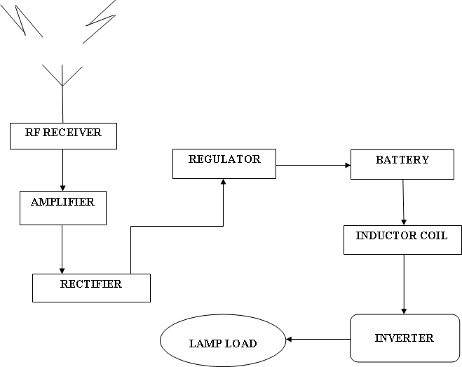 | Figure 1. Construction of an MREHS |
4.1.2. RF Transmitter and Receiver
- A complete RF transmitter module without any external components is used and hence no tuning is required. It is interfaced directly with encoders and microcontrollers. A complete super-regenerative compact RF module operating at 433.92 MHz is used as RF receiver.
4.1.3. Power Amplifier
- Darlington transistors and the shunt voltage feedback are used for power amplification. Such amplifiers provide increased output voltage on small resistance load.
4.1.4. Rectifier and Regulator
- A full-wave bridge rectifier is used to derive pulsating DC signal besides a capacitive filter and regulator (Figure 2). An IC 7805 fixed voltage regulator is used here.
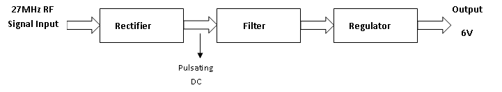 | Figure 2. Rectifier and regulator stage |
4.1.5. Storage Device
- The energy storage device may be a battery or a super-capacitor depending on the application. Lead-acid batteries are ideal to store harvested energy. These render greater lifetimes than expected in stand-alone PV systems than conventional batteries[19,20].
4.2. Functions of MREHS
- In our work, the RFID tag serves as the source and the transmitter. The distance between the transmitter and the receiver is approximately 1 m, assuming near-field energy harvesting. When activated, the RFID tag emits the RF signal, which is received by the receiver and kept at a specified distance from the transmitter. The received RF signal is then boosted by the amplifier.
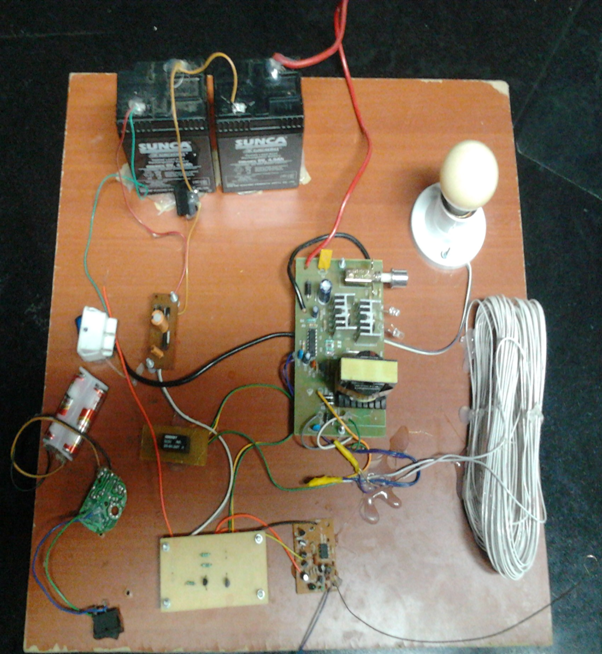 | Figure 3. Experimental setup for RF energy harvesting |
5. Experimental Results
- The schematic of the antenna and rectifier model developed is shown in Figure 4. Figure 5 depicts the input RF signal used for simulation. The rectified and filtered output is shown in Figure 6. By trial and error method, the source voltage for simulation was determined as 700 mV.
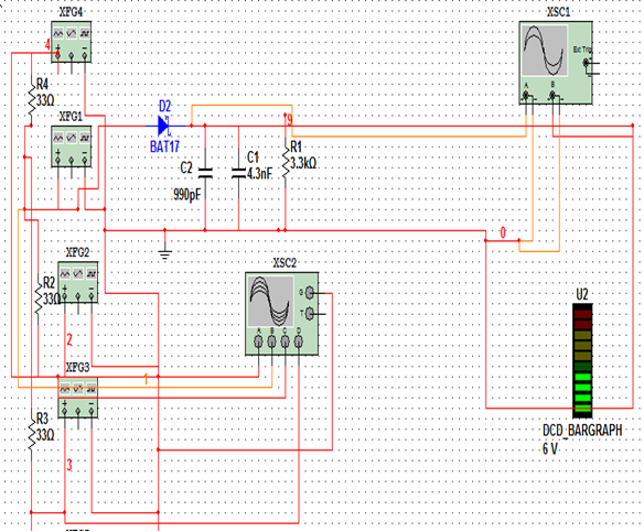 | Figure 4. Schematic of antenna and rectifier using Multisim |
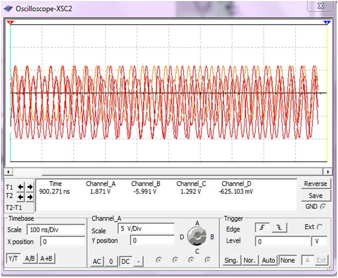 | Figure 5. Input RF signal |
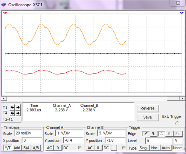 | Figure 6. Rectified and filtered output signal |
|
6. Conclusions
- In this paper, we present the experimental results of harvesting RF power using a RFID tag. The model could be easily scaled to different power levels by changing the distance of RFID tag from the receiver. High conversion efficiency will be maintained due to the adaptive optimization algorithms in use for MPPT. In addition, simulations to show how the RF energy has been received, amplified and then harvested were performed using Multisim software. The design is highly optimized and can be effectively adapted at larger scales with suitable drivers and increased storage capacity to energize significant loads for various applications. We welcome inputs from other researchers to further optimize the circuit design to maximize peak efficiency, efficiency range and frequency range.