-
Paper Information
- Paper Submission
-
Journal Information
- About This Journal
- Editorial Board
- Current Issue
- Archive
- Author Guidelines
- Contact Us
Energy and Power
p-ISSN: 2163-159X e-ISSN: 2163-1603
2026; 15(1): 1-3
doi:10.5923/j.ep.20261501.01
Received: Dec. 6, 2025; Accepted: Jan. 2, 2026; Published: Jan. 28, 2026

DC Motor Starting Current
 Abstract
 Reference
 Full-Text PDF
 Full-text HTML
Sarhan Hasan1, Aref M. Alkelani2, Ahmed Altaher Zuglem2, Abdelhamid Elgzil3, Osama Ali Elhenshiri4, Reda Elbahi5
1University of Denver, Colorado, USA
2Om Alrrabea Faculty of Sciences and Technology, Surman, Libya
3University of Colorado at Colorado Springs, USA
4Colorado Technical University, USA
5Rochester Institute of Technology, USA
Correspondence to: Sarhan Hasan, University of Denver, Colorado, USA.
| Email: |  |
Copyright © 2026 The Author(s). Published by Scientific & Academic Publishing.
This work is licensed under the Creative Commons Attribution International License (CC BY).
http://creativecommons.org/licenses/by/4.0/

The main purpose of this paper is to determine the behavior of a shunt DC motor during the starting period and to analyze how the motor line current changes compared to its rated current. At the time of starting, the armature of the shunt DC motor is stationary, and no back electromotive force (EMF) is generated to limit the current. Consequently, the motor draws a very high inrush current, often several times greater than its rated current. This study focuses on observing this starting behavior, examining how the current gradually decreases as the motor gains speed and back EMF builds up, and comparing these variations with the rated conditions. The findings aim to highlight the importance of current control methods and protective measures to ensure efficient and safe operation of shunt DC motors.
Keywords: DC motor, Starting current, Shunt motor
Cite this paper: Sarhan Hasan, Aref M. Alkelani, Ahmed Altaher Zuglem, Abdelhamid Elgzil, Osama Ali Elhenshiri, Reda Elbahi, DC Motor Starting Current, Energy and Power, Vol. 15 No. 1, 2026, pp. 1-3. doi: 10.5923/j.ep.20261501.01.
1. Methodolgy
- DC motors can be classified according to the way their field winding is connected to the armature winding. Based on this field connection, DC motors are mainly divided into three types: shunt-wound like in Fig. 1, series-wound, and compound-wound motors. In a shunt DC motor, the field winding is connected in parallel (shunt) with the armature, resulting in nearly constant speed under varying loads because the field current remains almost constant. In a series DC motor, the field winding is connected in series with the armature, so the same current flows through both. This gives the motor high starting torque but causes the speed to vary widely with load, making it suitable for applications like traction or cranes. The compound DC motor combines features of both shunt and series motors by having two field windings—one in series and the other in parallel with the armature—providing a balance between good starting torque and stable speed regulation. Compound motors can be further classified as cumulatively compounded or differentially compounded depending on how the series and shunt fields assist or oppose each other [1].
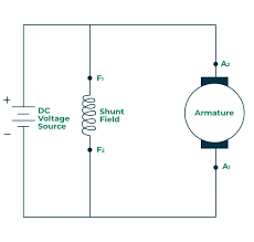 | Figure 1. Shunt DC motor [1] |
|

 | (1) |
 | (2) |
 | (3) |
 | (4) |
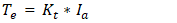
 : torque constant -N.m/A•
  : armature current -A•
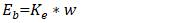
  is back MMF- V•
  : Back EMF constant V.s/rad•
  : angular speed in Rad/s•
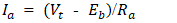
  : armature current A•
  : motor terminal voltage-V•
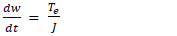
  : armature resistance - Ω• J: Moment of Inertia
  Euler’s Method:Euler’s Method is a numerical technique for approximating solutions to first-order ordinary differential equations (ODEs) of the form:
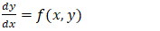 | (5) |
 is given by the differential equation
  .So we take a small step
  (step size) in the
  -direction and move in the direction of the slope.
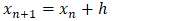 | (6) |
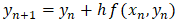 | (7) |
 approximates the true solution at
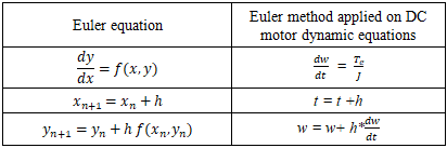
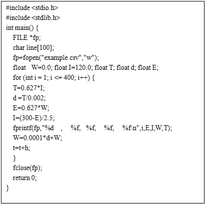
  .Euler’s method is simple, efficient, and easy to implement in real-time simulation codes were written in C language programming for this paper problem topic based on motor dynamic equations 1-4. Table 2 shows and illustrates the applied Euler method equation on DC dynamic equations, and Table 3 shows C codes solution for the same equations.
|
|
2. Results and Discussion
- Figure 2 illustrates the exponential decay of the motor’s starting current over time. At the moment of startup, the motor experiences a very high inrush current, reaching nearly nine to ten times the rated value—approximately 120 A compared to the nominal 15 A. This surge occurs because the back EMF is initially zero, allowing maximum current to flow through the armature. Although this high current gradually decreases as the motor accelerates, its presence can place significant stress on the winding insulation. Repeated exposure to such large current spikes can lead to excessive heating, insulation degradation, and eventual weakening of the motor’s electrical integrity, potentially reducing the motor’s lifespan or increasing the likelihood of insulation failure if not properly managed.
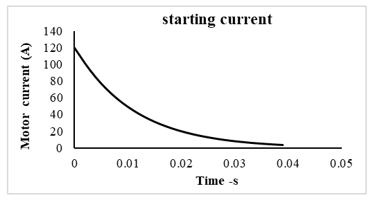 | Figure 2. Starting motor current variations |
3. Conclusions
- The analysis of the shunt DC motor’s starting behavior confirms that the motor draws a significantly high inrush current at the moment of startup due to the absence of back electromotive force (EMF). When the armature is stationary, no back EMF is generated to oppose the applied voltage, causing the armature current to reach values several times higher than the rated current. As the motor begins to accelerate, the back EMF gradually increases in proportion to speed, effectively reducing the armature current. This results in a smooth transition from high initial current to the normal operating current once steady-state speed is achieved. Numerical simulation using Euler’s method and the motor’s dynamic equations validates this characteristic behavior, showing a rapid current drop during the transient period as torque balance is established. The findings highlight the importance of incorporating current-limiting measures—such as starting resistors, soft starters, or electronic drives—to protect the motor against excessive electrical and thermal stress. Ultimately, understanding the starting current profile is essential for ensuring reliable operation, optimizing motor performance, and extending system lifespan.