R. Ouambo1, T. Djiako2, M. T. Tchawe3, T. Tchinda2, F. X. Ngagoum2
1Department of Energy and Process Engineering, UCAC-ICAM Institute, Douala, Cameroon
2Department of Energy and Mechanical Engineering, ISTA, University Institute of the Gulf of Guinea, Douala, Cameroon
3Department of Mechanical Engineering, ENSAI, University of Ngaoundere, Ngaoundere, Cameroon
Correspondence to: T. Djiako, Department of Energy and Mechanical Engineering, ISTA, University Institute of the Gulf of Guinea, Douala, Cameroon.
| Email: |  |
Copyright © 2023 The Author(s). Published by Scientific & Academic Publishing.
This work is licensed under the Creative Commons Attribution International License (CC BY).
http://creativecommons.org/licenses/by/4.0/

Abstract
Africa is generally witnessing a strong demographic expansion, with its population expected to almost doubled by 2100. This fact is the same in Cameroon, and will lead to a profound re-design of the electricity energy sources and distribution infrastructures over the coming years. However, and despite the government 2035 master plan to tackle that issue, we are currently facing a situation where lot of stresses are put on the electrical distribution system, from both the components aging and the continuous increase in the energy demand. This leads to serious grid reliability issues with a high rate of power outages, well known locally as “Delestages”. The traditional way of handling those power outages is by using thermal engine generators. However, the highly evolving renewable energy industry nowadays brings alternatives greener solutions in line with the worldwide decarbonization objectives. The presented work is a capitalization of 6 years of field experience in designing and installing green power backup solutions across Cameroon. The existing technologies are presented, both technically and economically. This led to a direct comparison with the thermal generator solutions, clearly demonstrating the superiority of the green power backup solutions financially and ergonomically wise. We have then presented a workflow for the design and selection of the green power backup technologies, based on the level of grid reliability, the type of activity and financial constraints. Some examples from the field were presented at the end, along with some critical operating and maintenance aspects.
Keywords:
Power outages, Alternatives greener solutions, Worldwide decarbonization objectives
Cite this paper: R. Ouambo, T. Djiako, M. T. Tchawe, T. Tchinda, F. X. Ngagoum, Green Power Backup Solutions: Technologies Overview and Selection Workflow in the Cameroonian Context, Energy and Power, Vol. 13 No. 1, 2023, pp. 1-9. doi: 10.5923/j.ep.20231301.01.
Article Outline
- 1. Introduction
- 2. Green Power Backup Technologies
- 2.1. Power Backup Based on Offline Inverters
- 2.2. Power Backup Based on Online Inverters
- 2.3. Power Backup with Hybrid Grid/PV Source
- 2.4. Comparison of the Different Solutions
- 2.5. Current Inverter and Batteries Technologies
- 2.5.1. Inverters Technology
- 2.5.2. Batteries Technology
- 3. Design Workflow and Examples
- 3.1. Design Workflow Batteries Only Based Solutions
- 3.1.1. Step 1: Location Characterization
- 3.1.2. Step 2: Power Balance of the Essential Equipment
- 3.1.3. Step 3: Electrical Installation Assessment
- 3.1.4. Step 4: Installation Room Localization and Assessment
- 3.1.5. Step 5: Inverter Selection
- 3.1.6. Step 6: Batteries Sizing
- 3.1.7. Step 7: Protective Devices Sizing
- 3.1.8. Step 8: Installation and Commissioning
- 3.2. Workflow for Grid/PV Hybrid Solutions
- 3.3. Field Examples
- 3.3.1. Example 1: Inverter 40 kVA Offline Low Frequency, 72 kWh of GEL Batteries, Yaoundé – Cameroon
- 3.3.2. Example 2: Inverter 15 kVA Online Low Frequency, 36 kWh of GEL Batteries, Yaoundé – Cameroon
- 3.3.3. Example 3: Inverter 5 kVA Offline Low Frequency, 10 kWh of Lithium Battery, Dschang - Cameroon
- 3.3.4. Example 4: Inverter 2 x 10 kVA Hybrid Offline Low Frequency, 58kWh of GEL Battery, 18kW of PV Panels, with Remote Monitoring, Douala - Cameroon
- 3.4. Critical Maintenance Steps
- 4. Comparison with Thermal Generators
- 5. Conclusions
- ACKNOWLEDGEMENTS
1. Introduction
Africa is generally witnessing a strong demographic expansion, with its population expected to almost doubled by 2100 [17]. New urban centers are being created, and existing ones have expanded tremendously over the past decades. However, the existing grid structures did not cope with that rapid energy demand from the demographic expansion. Adding to that the ageing of the grip equipment, some African countries are nowadays facing huge reliability issues with the electricity power generation and distribution.In Cameroon, the government 2035 master plan [15] is in place, trying to cope with the situation. But despite the work being done, the country is facing large scale grid instabilities and we can expect the situation to still last for several years. Power outages, locally called “Delestages” is hence more or less frequent, depending on locations and seasons. The traditional way of coping with the outages is by installing thermal generators and a power transfer switch, either automatic or manual one.The 2050 worldwide decarbonization objectives have led to rapid development of renewable energy technologies, including power backup solutions [3]. In this work we will present the current power backup technologies from the Cameroonian market from our past 6 years experience of designing and installing those solutions. We will then present a workflow for designing [1] and installing [5] green power backup technologies, followed by some field examples. We will end by performing a comparison with the thermal generator solution on a given case.
2. Green Power Backup Technologies
Power backup technologies are intended for areas covered by the electrical grid, and provide energy continuity in case of power outages that can last up to several hours. The basic principle is to store the energy from the grid into deep cycle batteries, and then use that stored energy to supply the needs in case of power outage [2]. There are currently two main family of green power backup solutions on the Cameroonian market:- Power backup based on offline inverters;- Power backup based on online inverters.
2.1. Power Backup Based on Offline Inverters
In this solution, the sequence of operations inside the inverter is the following:- When the grid is present:- Grid power is connected to the load via a transfer switch;- Battery is charged via an AC-DC charger;- When the grid is absent:- AC power is generated via an DC-AC converter;- The generated AC power is connected to the load via a transfer switch.Most of the manufacturers are nowadays providing at low cost options for remote monitoring and supervision once an internet network is available. Figure 1 shows an example of backup solution based on offline inverter. 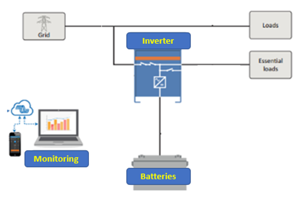 | Figure 1. Power backup based on offline inverter structure [18] |
2.2. Power Backup Based on Online Inverters
This solution is based on the double conversion principle, as shown in the Figure 2. Here there is no transfer switch and the grid power is never directly connected to the load.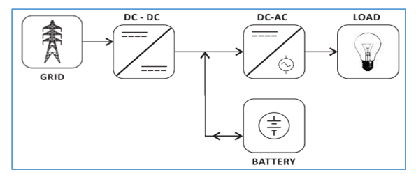 | Figure 2. Power backup based on online inverter structure [18] |
2.3. Power Backup with Hybrid Grid/PV Source
On the each of the two solutions above, there is the possibility of having an additional battery PV charge controller, either integrated in the inverter or external. This can help two purposes:- Increasing the autonomy of the system in case of power outage;- Reducing the system life cycle cost by feeding in the solar PV energy [6].Figure 3 shows an example on online inverter with integrated PV charge controller.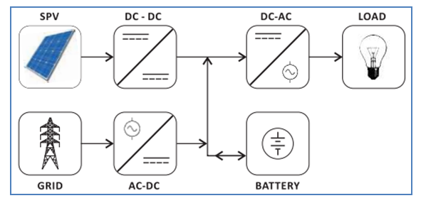 | Figure 3. Power backup based on online inverter with integrated solar PV charge controller [18] |
Looking at the PV panel prices evolution during the past years, the hybrid solution is very attractive economically as we will see later [7].In Figure 4 we can see the average evolution trend of the PV panels market prices in FCFA in Cameroon since 2016, from our local market observations in Douala city.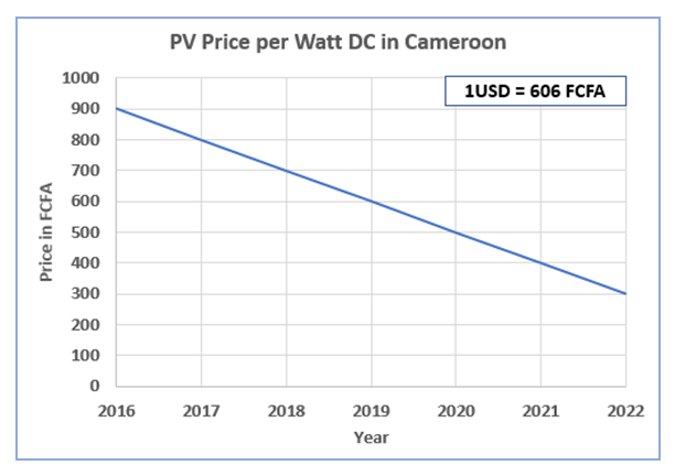 | Figure 4. Solar PV price evolution in Cameroon |
Let’s note here that some inverter on the market provide the ability to feed in the grid any excess energy produced. However, the current Cameroonian legislation does not cover yet such operations.
2.4. Comparison of the Different Solutions
Table 1 shows a comparison between the different technological solutions presented. | Table 1. Power Backup Technologies Comparison |
2.5. Current Inverter and Batteries Technologies
The table above shows a comparison between the different technological solutions presented.
2.5.1. Inverters Technology
Typically, there are three main inverter technologies nowadays on the market:- High frequency transformer less inverter;- Low frequency with toroidal core transformer;- Low frequency with cylindrical core transformer.Because of the transformers current damping effect, the low frequency inverters are recommended for load with high current surges such as air conditioning. Toroidal core transformers are typically more compact and more efficient than the cylindrical core ones. Figure 5 presents a comparison made of a 5kVA offline inverter for each technology [18].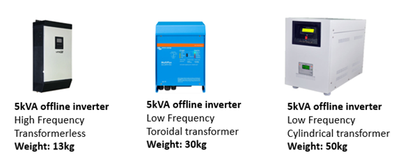 | Figure 5. Examples of 5kVA offline inverters of various technologies |
2.5.2. Batteries Technology
There are two main batteries type on the market: Lead and Lithium ones [4]. The Graph below shows the current existing technologies on the market and some number on their life cycle versus depth of discharge (DoD).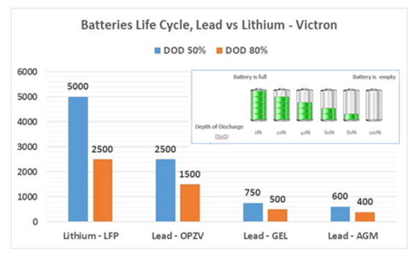 | Figure 6. Batteries technologies and typical life span [18] |
The worldwide costs reductions in Lithium battery are making them very attractive nowadays [13], are they becoming even cheaper than the Lead OPZV batteries [14].
3. Design Workflow and Examples
3.1. Design Workflow Batteries Only Based Solutions
In this section, we will present a workflow that has been used successfully over years for proper selection and sizing of the power backup solution only based on battery storage [8].That workflow is a sequential one, made of several steps (see Figure 7a)
3.1.1. Step 1: Location Characterization
Here will classify the location based on the duration and frequencies of the power outages, using the table and matrix in Figure 7b.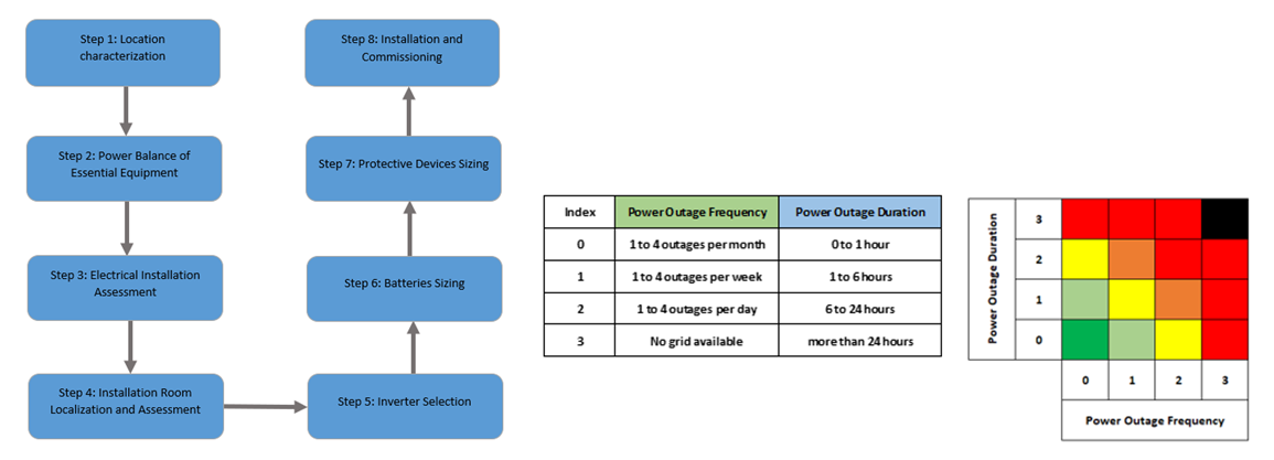 | Figure 7. a) Workflow for battery only based solution. b) Location characterization matrix |
3.1.2. Step 2: Power Balance of the Essential Equipment
- Design power outage time (DPOT): this is the desired time for which the backup system is expected to last during a power cut. It is fixed in conjunction with the end user, based on the classification from Step 1. An example of power balance is presented in Table 2.- Once the DPOT is known, a power balance of the essential equipment is made, taking into account each equipment power, working time and starting surge factor. Below is an example.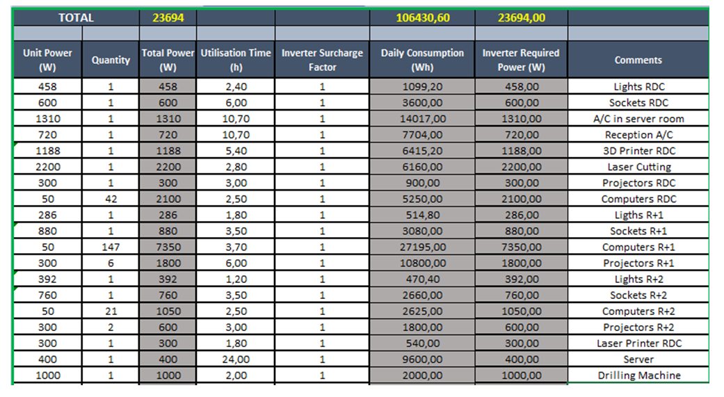 | Table 2. Essential loads power balance example |
From the power balance we can get:- The Total installed power (PTOT);- The consumed energy during a power outage (ETOT);- The effective power required from the inverter (PEFF), and taking into account starting surges.
3.1.3. Step 3: Electrical Installation Assessment
After the power balance, the existing electrical installation need to be accessed for the following:- Number of phases;- Grid power subscription details (meter caliber, …);- Distribution details: are the essential loads circuits well separated.
3.1.4. Step 4: Installation Room Localization and Assessment
The next phase is to know where the system will be located:- Proximity from the main electrical box;- Ventilation;- Water infiltrations;- Dusts infiltrations.
3.1.5. Step 5: Inverter Selection
The inverter is selected based on:- The effective required power PEFF;- The requirement for zero time power transfer (some sensitive equipment may not allow a transfer time of even few ms): online inverters in that case;- The requirement for high quality power output: online inverters in that case;- The presence of high surge equipment: low frequency inverters in that case;- The number of phases: for the three phases option, the solution is a three phases inverter or setting inverters in parallel.
3.1.6. Step 6: Batteries Sizing
Battery sizing is a compromise between operationality and economical aspects of the systematic battery replacement costs [9]. Hence the idea is to make simulations of many scenarios and at the end select the scenario that suits best the financial constraints [10]. The main parameters that will aid in battery sizing are:- Number of power outages per year, based on the classification matrix: POY- Discharged energy per power outage: | (1) |
(NREN being the system efficiency, 0.9 being a good estimation)- Discharged Energy per year from power outages: | (2) |
- Total installed capacity: CTOT- Depth of discharged at each power cut: DOD- Number of life cycles for DOD: NCYCLE- End of life discharged energy:  | (3) |
(NENV being an environmental correction factor, typically 0.75)- Number of years till end of life:  | (4) |
For recommended maximum DOD for lead batteries is 50% and 80% for Lithium batteries. The presented batteries life model is a simplified Ah-Throughput model. Figure 8 provides an example of scenarios simulations for sizing.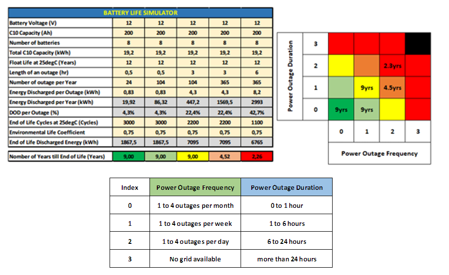 | Figure 8. Example of batteries scenarios simulations |
3.1.7. Step 7: Protective Devices Sizing
Next step will be the sizing of protecting devices:- Batteries short-circuit protection fuses;- Earthing regime verifications;- Surge protection devices.
3.1.8. Step 8: Installation and Commissioning
The final step is installing and commissioning the system. This phase is very important as in addition to verifying the functionality, it helps acquiring data which will be critical for continuous improvement processes. It is very important to document this phase with proper commissioning check lists.
3.2. Workflow for Grid/PV Hybrid Solutions
The workflow here requires more complex calculations and hence we have designed a software tool helping into it. The main difference with the previously presented workflow lies in the PV-Batteries couple sizing. In Figure 9 we present how this sizing is achieved using our software tool.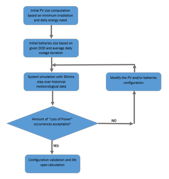 | Figure 9. Workflow for PV-Batteries sizing |
3.3. Field Examples
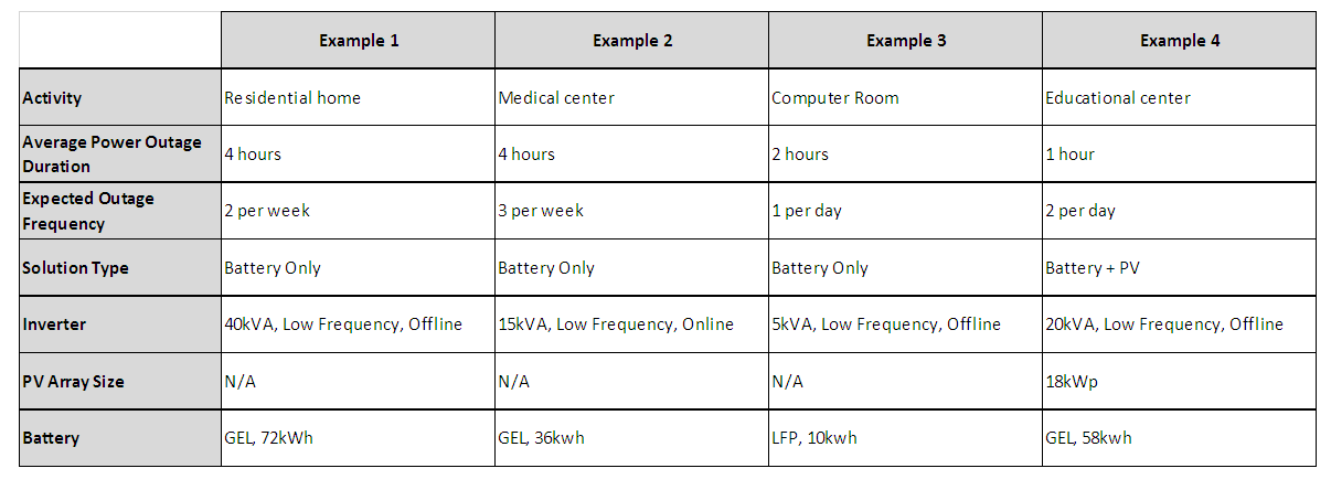
We will present here couple of field examples from the technologies outlined. Each presented example was designed using the presented workflows, with the objective of coping with the power outages based on activity, essential loads and financial constraints. The comparison is presented only on a financial point of view.
3.3.1. Example 1: Inverter 40 kVA Offline Low Frequency, 72 kWh of GEL Batteries, Yaoundé – Cameroon
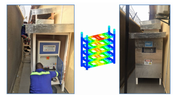 | Figure 10. Example 1 picture |
3.3.2. Example 2: Inverter 15 kVA Online Low Frequency, 36 kWh of GEL Batteries, Yaoundé – Cameroon
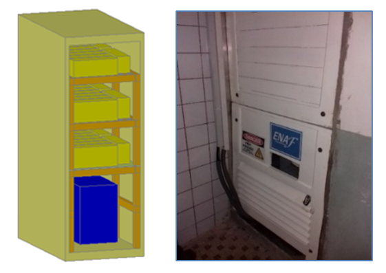 | Figure 11. Example 2 picture |
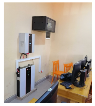
3.3.3. Example 3: Inverter 5 kVA Offline Low Frequency, 10 kWh of Lithium Battery, Dschang - Cameroon
 | Figure 12. Example 3 picture |
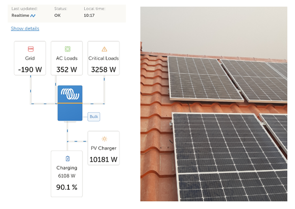
3.3.4. Example 4: Inverter 2 x 10 kVA Hybrid Offline Low Frequency, 58kWh of GEL Battery, 18kW of PV Panels, with Remote Monitoring, Douala - Cameroon
 | Figure 13. Example 4 picture |
3.4. Critical Maintenance Steps
Once installed, the main requirements for systematic maintenance will be:- Dust cleaning;- Bolts tightening;- Voltages measurements to ensure good batteries bank balancing;- Batteries conditions check (cracks, overheating, …);- Solar panels cleaning;- Solar panels check for hot spots;- Protectives devices condition checks;- Wirings conditions checks;- Inverters alarms log review.
4. Comparison with Thermal Generators
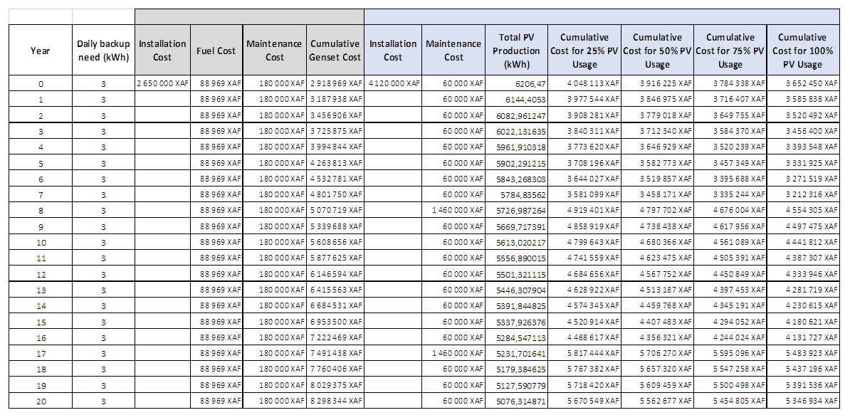
In this section we will perform a comparison between an hybrid power backup with online inverter and the thermal generator solution. The comparison will be based only on a financial point of view,The architecture the system is as below: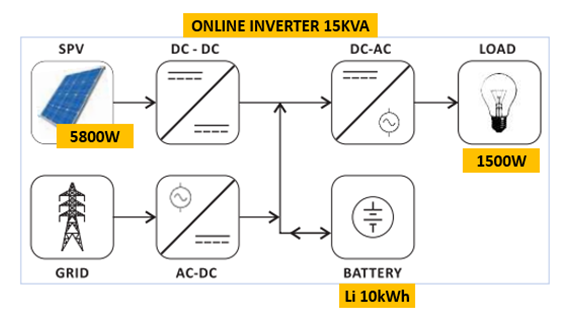 | Figure 14. Architecture of the system used for comparison |
- Inverter: hybrid online 15kVa;- PV panels: 5800Wp (rooftop with 50% installed on east side and 50% on west side);- Batteries: Lithium 10kWh (replacement frequency: 8 years);- Daily average outage duration: 02 hours.The equivalent generator installed is:- 10kVA genset;- ATS switch 100A.We have then made a cost simulation with the following assumptions:- Grid Energy cost per kwh: 0.85;- Generator consumption per kwh: 8liters;- Diesel cost per liter: 650 XAF (1USD = 606 XAF);- PV panel power degradation year to year: 1%;- Li Battery replacement frequency: 8 years;- Currency actualization or depreciation: not accounted for;- Genset maintenance costs: assumed constant over years (no ageing accounted for);- Actual Cameroonian standard market prices are used for both presented solutions.Below are the resulting table and graph.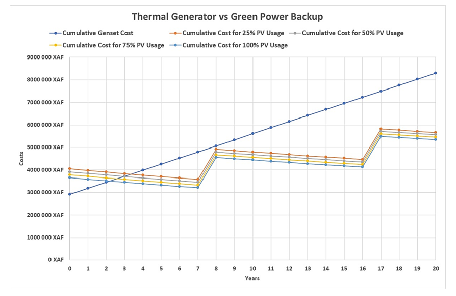 | Figure 15. Comparison table and graph results |
 | Table 3. Comparison table and graph results |
 | Table 4 |
As we can see:- Initial costs are well in favor of the thermal generator solution;- However, before the 4th year the green backup solution is already more rentable;- The more the PV panels energy is used, the more economies are paid, leading to a cumulative cost of the green power solution decreasing in time, right after a batterie replacement. The PV energy almost pays off the battery replacement costs.
5. Conclusions
This work capitalizes the authors experience over 6 years of installing nearly 100 power backup systems across Cameroon. We have started by presenting the different technologies available nowadays that can be used as green alternative to the traditional use of thermal generators. Here it was interesting to note the sharp decrease of the PV panel price over the past years, making the PV energy generation very attractive economically.We have then presented a selection, sizing and installation workflow that currently being used in the field with very good results, followed by few maintenance tips. The last part of this work concerned the comparison between a green power backup solution and the thermal generator one for a particular case and with very conservative assumptions. This showed the superior rentability of the green power backup solution, with in addition the eventual energy produced by the PV panels slowly compensating the battery replacement costs.
ACKNOWLEDGEMENTS
We greatly thank the IUG for the partnership with the actors of the socio-economic sector who participate actively in the development of our country.
References
| [1] | H. Yuan, H. Ye, Y. Chen, W. Deng, Research on the optimal configuration of photovoltaic and energy storage in rural microgrid, The 5th International Conference on Electrical Engineering and Green Energy, CEEGE 2022, 8-11 June, Berlin, Germany, Energy Reports, Volume 8, Supplement 13, November 2022, Pages 1285-1293. |
| [2] | A. Chakir, M. Tabaa, F. Moutaouakkil, H. Medromi, M. Julien-Salame, A. Dandache. Optimal energy management for a grid connected PV-battery system, Science Direct, Energy Rep, 6, 2020, pp. 218-231. |
| [3] | S. J. Chiang, K. T. Chang, C. Y. Yen, Residential photovoltaic energy storage system, IEEE, Institute of Electrical and Electronics Engineers, Transactions on Industrial Electronics, Vol. 45, Issue 3, 1998, pp. 385-394. |
| [4] | S. P. Ayeng'o, T. Schirmer, D. U. Sauer, Comparison of off-grid power supply systems using lead-acid and lithium-ion batteries, Solar Energy1, 2018. |
| [5] | J. Royer, T. Djiako, E. Schiller, B. Sada Sy, Le Pompage Photovoltaique, IEPF/Université d’Ottawa/EIER/CREPA, ISBN 2-89481-006-7, 1998. |
| [6] | A. Mermoud, “PVsyst: Software for the Study and Simulation of Photovoltaic Systems”, ISE, University of Geneva, www.pvsyst.com. |
| [7] | H. Akbari, M.C. Browne, A. Ortega, M. J. Huang, N. J. Hewitt, B. Norton, S. J. McCormack, Efficient energy storage technologies for photovoltaic systems, Solar Energy, 2018. |
| [8] | X.G. Wu, Z.Q. Liu, L.T. Tian, Optimized capacity configuration of photovoltaic generation and energy storage device for stand-alone photovoltaic generation system, Power Syst. Technol., 38-05, 2014, pp. 1271-1276. |
| [9] | S. Freitas, C. Reinhart, M. C. Brito, Minimizing storage needs for large scale photovoltaic in the urban environment, Solar Energy1, 2018. |
| [10] | S. Agnew, P. Dargusch, Effect of residential solar and storage on centralized electricity supply systems, Nature Climate Change volume 5, pages 315-318, 2015. |
| [11] | A. Zahedi, Maximizing solar PV energy penetration using energy storage technology, Renewable and Sustainable energy Reviews, Vol. 15, Issue 1, January 2011, Pages 866-870. |
| [12] | F. M. Vieira, A. T. de Almeida, Energy storage system for self-consumption of photovoltaic energy in residential zero energy buildings, Renewable Energy, Volume 103, 2017, pp. 308-320. |
| [13] | V. Vega-Garita, L. Ramirez-Elizondo, N. Narayan, P. Bauer, Integrating a photovoltaic storage system in one device: A critical review, Progress in Photovoltaics: Research and Applications, 2019, Wiley Online Library. |
| [14] | M. Upasani, S. Patil, Grid connected solar photovoltaic system with battery storage for energy management, IEEE, Institute of Electrical and Electronics Engineers, 2nd International Conference on Inventive Systems and Control (ICISC), 19-20 January 2018, Coimbatore, India. |
| [15] | Ministry of Economy, Planning and Regional Development, Cameroon 2035 Viision, 2009. |
| [16] | United State Agency for International Development, Off-Grid Solar Market Assessment for Cameroon, Power Africa, October 2019. |
| [17] | UN Department of Economics and Social Affairs, World Population Prospect 2022, United Nations, New York, 2022. |
| [18] | R. Ouambo, Photovoltaic Systems Course, Gulf of Guinea University Institute, 2021. |


 Abstract
 Reference
 Full-Text PDF
 Full-text HTML


