M. Marouf Wani
Mechanical Engineering Department, National Institute of Technology, J&K, Srinagar, India
Correspondence to: M. Marouf Wani, Mechanical Engineering Department, National Institute of Technology, J&K, Srinagar, India.
| Email: |  |
Copyright © 2021 The Author(s). Published by Scientific & Academic Publishing.
This work is licensed under the Creative Commons Attribution International License (CC BY).
http://creativecommons.org/licenses/by/4.0/

Abstract
This paper presents the results on the CFD investigations on the digital valve mechanism of a single cylinder spark ignition engine using the numerical finite volume method. The investigations were done by replacing the conventional valves by the digital valves with an aim to improve the volumetric efficiency and therefore the performance parameters and emissions characteristics. The thermodynamic simulation software AVL BOOST was used for computational investigations for both the cases. The software is based on the solution of thermodynamic conservation equations of mass, momentum, energy and the equation of state for an ideal gas. The engine performance and emissions parameters were computed for both the conventional cam and follower based valve mechanism and the proposed digital valve mechanism. The digital valve system was designed for a constant valve lift for all crank angles involved during gas exchange process whereas the conventional cam and follower type valve system design has a variable valve lift from crank angle to crank angle during gas exchange period. The results showed that with proposed digital valve system the performance parameters like volumetric efficiency and therefore power, torque, brake specific fuel consumption were better as compared to the conventional cam and follower type valve system design. The engine designed with digital valves produces less CO and HC emissions. Also the specific weight of the engine designed with digital valve system is likely to be lesser than the conventional engine.
Keywords:
Engine, Spark Ignition, Digital Valves, Valve Lift, CFD, Volumetric Efficiency, Numerical Method, Performance and Emissions
Cite this paper: M. Marouf Wani, CFD Investigations of a Single Cylinder Spark Ignition Engine Using Digital Valve Mechanism, Energy and Power, Vol. 11 No. 1, 2021, pp. 26-32. doi: 10.5923/j.ep.20211101.03.
1. Introduction
Computational fluid dynamic investigations can be used to improve the thermodynamic and gas dynamic design of the intake and exhaust gas manifolds of an internal combustion engine. Intake manifold design affects the engine performance parameters like volumetric efficiency, power, torque, brake specific fuel consumption and its emissions characteristics. The exhaust gas manifold design involves the catalytic convertors used for emission control, mufflers used to control noise, EGR system introduced to reduce the NOX emissions from engine. Turbocharger design and matching, used for power boosting or engine downsizing, can be optimized using the CFD involving numerical finite volume method. The amplitude of the reflected waves with changing crank angles has to be minimized to maximize volumetric efficiency of the engine. The proposed digital valve system will decrease the amplitude of the reflected waves on a crank angle to crank angle basis as compared to the conventional cam and follower based valve operating system. This is turn will improve engine performance parameters and also minimize the emissions.
2. Literature Survey
Two basic types of models have been developed for the processes that govern the performance and emissions of I C engines. The models are categorized as thermodynamic or fluid dynamic in nature. It depends whether the equations which give the model are based on energy conservation or on a full analysis of the fluid motion. Thermodynamic energy conservation based models are: Zero – dimensional, since in absence of any flow modeling, geometric features of the fluid motion cannot be predicted; Phenomenological, additional detail beyond the energy conservation equations is added for each phenomenon in turn; Quasi-dimensional, specific geometric features, e.g., the spark-ignition engine flame or the diesel fuel spray shapes, are added to the basic thermodynamic approach; Fluid-dynamic based models or multidimensional models, these have inherent ability to provide detailed geometric information on the flow field based on solution of the governing flow equations of conservation of mass, energy and momentum. In gas exchange processes in internal combustion engines, volumetric efficiency is used as an overall measure of the effectiveness of a four stroke cycle engine and its intake and exhaust systems as an air pumping device. Air flow constrains maximizing the engine power. lesser air flow in SI engines are obtained by restricting the intake system flow area with the throttle valve. Volumetric efficiency is affected by the fuel, engine design, and engine operating variables like fuel type, fuel/air ratio, fraction of fuel vaporized in the intake system, heat of vaporization of the fuel, mixture temperature as influenced by heat transfer, ratio of exhaust to inlet manifold pressures, compression ratio, engine speed, intake and exhaust manifold design, port design and intake and exhaust valve geometry, size, lift, and timings. [1]Wayland A. Tenkku writes in his technical paper that small solenoid operated cartridge valves provide flexibility to supply many functions in hydraulic systems. A line of solenoid operated two way, two position cartridge directional control valves has been developed in conjunction with a series of solenoid coils with different terminations. The coils are completely interchangeable with any of the valves. Additional development in solenoid operated cartridge valves has resulted in a co-axial solenoid cartridge relief valve which can also utilize the same solenoid coils as the other valves. [2]Cole C., et.al., conducted experimental investigations on the application of digital valve technology to diesel fuel injection. The design and advantages of the digital valve were presented. Further the versatility of the digital hydraulic operating system injector were presented. The main advantage of the digital valve over a conventional solenoid include high speed, increased energy efficiency, inherent feedback, and small package size. The digital valve consists of a spool, two electromagnetic coils, and the valve housing. The spool is pulled towards the open or closed position by attractive magnetic forces produced by the open or closed coil respectively. The valve is faster than a typical solenoid primarily because it does not have to work against a mechanical spring. Furthermore once in position, the valve requires no additional energy but instead uses residual magnetism to stay latched in position. In addition, the digital valve’s two-coil design allows for the monitoring of back-EMF signals which can be used for position sensing. The DHOS injector can electronically control the start, duration, and rate of injection events. [3]Asano, M. et. al., writes in his technical paper that an electronic engine control system that uses a microcomputer has been developed. It combines four control systems – fuel injection, ignition timing, EGR and idle speed control – utilizing the engine speed and intake air quantity for its main parameters. The control circuit is composed of an 8-bit microcomputer combining an 8k byte ROM, RAM, a custom designed input/output LSI, and two hybrid integrated circuits, one has voltage regulators and other has input/output interface circuits. [4]Morel, T., et al., conducted one-dimensional fluid dynamic simulations of the flow in the engine manifolds, exhaust and intake elements with an objective to design it both for engine performance as well as for engine acoustics. The experimental investigations that followed verified the prediction of the good results based on simulation. [5]Maftouni, N., et al conducted 3-D simulations on the intake manifold of a XU7 Engine under steady state and unsteady state operation using 3-D CFD code. The simulations were carried out with three different runner lengths of 110, 120 and 130% of the original to see its effects on the volumetric efficiency of the engine under variable speed operation. The steady state results were compared with the flow bench rig based data for validation. 1-D WAVE code was used for generating the boundary condition for unsteady state simulation. The results showed that the volumetric efficiency of the engine increases with 120% runner length. [6]Pal, D., et al., conducted simulation studies on the design of intake manifolds in order to achieve a required level of engine performance. First of all the simulations were done using 1-D CFD code to optimize various parameters of the intake manifold. A few shortlisted designs were tested experimentally which showed strong correlation with simulated results. The second series of investigations was done by using a 3D CFD code for the intake manifolds to analyze the 3D effects of the manifold geometry. The third set of simulations was carried out to tune the manifold geometry further for possible optimum dimensions by using a coupled 1D and 3D CFD code. The results showed that the simulation studies lead to a better prediction of the engine performance. The 3D CFD simulations can give the detailed information about fluid and flow properties in complex 3D domains while 1D CFD simulation can provide important information at a system level, i.e about the performance of the entire engine. The drawbacks of the two simulation methods are that the former requires high computational cost while the latter is not able to capture complex local 3D features. [7]Testa, F., et al conducted computational analysis of the unsteady flow in a single cylinder two stroke gasoline engine using advanced numerical tools. The results were validated by the experimental measurements. A STAR-CD code based 3D model was used for the entire engine. Also a GT-POWER 1D and Converge-LITE 3D codes based 1D-3D integrated fluid dynamics model was used for predicting the performance and gas-dynamics in the whole intake and exhaust systems. The results showed that the methodology accurately predicted the phenomena in whole engine. Further it was observed that the wave motion based analysis strongly affects 3D design of muffler in small two stroke engines. [8] Fortunate, F., et al conducted transient CFD investigations of the exhaust gas manifold fitted with a catalyst. The new European driving cycle, NEDC, was adopted for these transient simulations to evaluate the vehicle fuel economy and its emissions characteristics. Further the effect of the exhaust gas temperature on the catalyst light-off time were also simulated by designing manifolds with different configurations and materials. The computed results were reasonably validated by the experimental investigations. The results showed that a thin exhaust gas manifold made of steel improves the thermal light-off of the catalytic convertor as compared to a similar manifold made of thicker cast iron. [9]Nanni, D. et al., conducted experimental investigations on the silencer of a motorcycle engine to validate the CFD model simulated to predict the performance of the same. The experiments were conducted on a test bench where the mass flow rate of the exhaust gas through the silencer was measured for several inlet-outlet pressure gradients. The finite volume method based numerical data for mass flow rate was computed for the same with several mesh sizes and computational settings. The results showed that the finite-volume model is a promising method for analyzing the performance of silencers with different designs. Further the FVM model does not give 100% accurate results to predict the absolute performance of the silencers. [10]
3. Theoretical Basis [11,12]
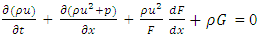
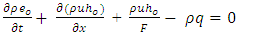
Conservation Equations for mass, momentum and energy in the following form are used for solving the research problems related to 1-Dimensional compressible flow of gas in a pipe.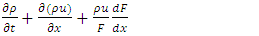 | (1) |
 | (2) |
 | (3) |
where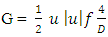 | (4) |
The term  is used to ensure that the pipe wall friction always opposes the fluid motionThe above three equations written in conservation law form can be written in symbolic vector form as
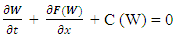 | (5) |
Computation of thermodynamic and gas dynamic properties of the gas throughout the pipe length is done by solving the conservation equations for getting the numerical values of various properties by integration as follows: The equations are integrated with respect to time step and length step limits. The integral form of the governing equations can be written as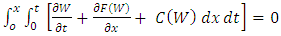 | (6) |
where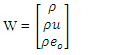 | (7) |
 | (8) |
and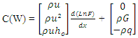 | (9) |
Equation (6) on integration, gives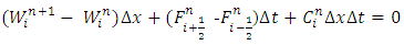 | (10) |
In this equation, W represents the average of dependent variables for the cell given by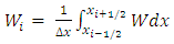 | (11) |
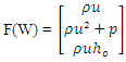
And F is the average flux across cell boundaries over an interval of time  , given by
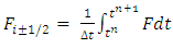 | (12) |
Equation (10) is the fully discrete, integral form of the one-dimensional system of conservation laws defined already.When the vector of source terms, C, is omitted, equation (10) reduces to the form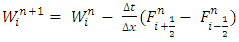 | (13) |
The left-hand side of the equation represents the solution at the new time level n+1, and the first term on the right-hand side represents the solution at time level n. Summing this equation with respect to the spatial index, i, and omitting source terms gives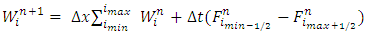 | (14) |
The equations were applied to fluid flow through a pipe of constant cross-sectional area, where  and
and  are the fluxes through the extreme ends of the pipe, all internal fluxes cancel out. This guarantees the integral form of the conservation equations, thereby ensuring, for example, the conservation of mass through a pipe.The finite difference methods used above when interpreted in the form of equations (10) to (12) are called conservative, finite volume schemes.
3.1. CFL Stability Criterion
During the course of numerical integration of the conservation laws defined in the Eq.1, Eq.2 and Eq.3, special attention should be focused on the control of the time step. In order to achieve a stable solution, the CFL criterion (stability criterion defined by Courant, Friedrichs and Lewy ) must be met: | (15) |
4. Results and Discussions
4.1. The Effect of Speed on the Volumetric Efficiency of the Engine with Digital and Cam Based Valve Mechanism Design
The Fig. 1 below shows the effect of engine speed on the volumetric efficiency with cam and follower and digital valve mechanisms. It is seen that the volumetric efficiency varies with respect to engine speed. The volumetric efficiency is maximum at the speed of 2000rpm and decreases on its either side.At the speed of 2000rpm the corresponding reciprocating piston speed suits the ingoing compression waves generated as a result of outgoing rarefaction wave resulting in maximum volumetric efficiency. This speed favors the superposition of the inward moving wave and the outward moving wave as per the application of D Alembert’s principle, thus maximizing the volumetric efficiency. The digital valves result in higher volumetric efficiency as compared to the cam and follower type valve mechanism. This is because of constant maximum lift with this valve which maximizes the effective flow area available for all crank angles of gas exchange and thus further simultaneously maintains a higher value for its coefficient of discharge.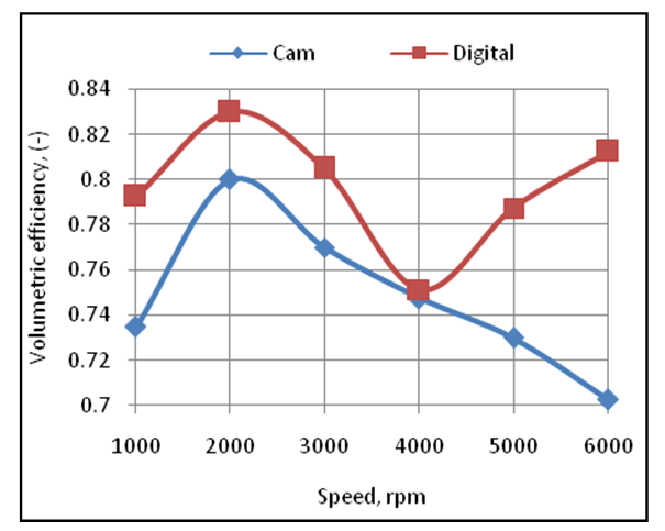 | Figure 1. Effect of Engine Speed on the Volumetric Efficiency of the Engine with Cam and Follower and Digital Valve Mechanism |
4.2. The Effect of Speed on the Power Developed by the Engine with Digital and Cam Based Valve Mechanism Design
The Fig. 2 below shows the effect of engine speed on the power developed by the engine. It is seen that the power developed by the engine varies with respect to engine speed. A higher power is obtained at higher speeds due to more number of power cycles per unit time.Further the engine develops more power with digital valves as compared to the cam and follower type of valves. This is because the volumetric efficiency of the engine is higher with digital valve mechanism which makes higher mass of air and therefore higher mass of fuel to enter the engine during each cycle. This in turn produces more power with digital valve mechanism.  | Figure 2. Effect of Speed on the Power Developed by the Engine with Cam and Follower and Digital Valve Activating Mechanism |
4.3. The Effect of Speed on the Torque Developed by the Engine with Digital and Cam Based Valve Mechanism Design
The Fig. 3 below shows the effect of speed on the torque developed by the engine. It is seen that the torque developed by the engine varies with engine speed. The engine develops maximum torque at the speed of 2000rpm. This is because at this speed the volumetric efficiency of the engine is maximum. More mass of charge per cycle produces more torque at this speed.Further the torque developed by the engine with digital valve mechanism is higher than the torque developed by the engine with cam and follower type valve mechanism. This is because the volumetric efficiency with digital valves is higher than the volumetric efficiency with cam and follower based valves. 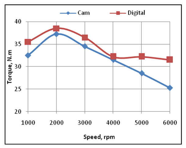 | Figure 3. Effect of Speed on the Torque Developed by the Engine with Cam and Follower and Digital Valve Activating Mechanisms |
4.4. The Effect of Speed on the Brake Specific Fuel Consumption of the Engine with Digital and Cam Based Valve Mechanism Design
The Fig. 4 below shows the effect of engine speed on the brake specific fuel consumption (BSFC) of the engine. It is seen that the BSFC of the engine varies with respect to the engine speed. The BSFC is minimum at the engine speed of 2000rpm. This is because the magnitude of the term power dominates first which decreases the magnitude of BSFC up to the engine speed of 2000rpm and beyond this speed the magnitude of the term mass flow rate of the fuel dominates which increases the magnitude of BSFC. Further the BSFC is lower with digital valve mechanism based engine as compared to the cam and follower valve mechanism based engine. This is because both the volumetric efficiency and power are higher with digital valve mechanism based engine design. 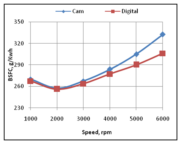 | Figure 4. Effect of Speed on the Brake Specific Fuel Consumption of the Engine with Cam and Follower and Digital Valve Activating Mechanisms |
4.5. The Effect of Speed on the CO Emissions Produced by the Engine with Digital and Cam Based Valve Mechanism Design
The CO emissions vary with respect to speed for both types of valve actuating mechanisms. The digital valve system engine produces less CO emissions due to higher volumetric efficiency, better mixture preparation and better combustion. With digital valves the concept of pressure wave supercharging helps to increase the air density further in the engine cylinder. With digital valves the magnitude of the stagnation parameters of pressure, density, velocity and temperature are higher as compared to the stagnation values of the corresponding terms for cam and follower type of valve operating system. With open digital valve the air behaves like an air spring and gets compressed to a higher density. The charge mixing and mixture preparation is better with digital valves due to higher pressure, higher temperature, higher velocity and higher Reynolds number based flow. This is in turn results in better combustion and lower CO emissions. 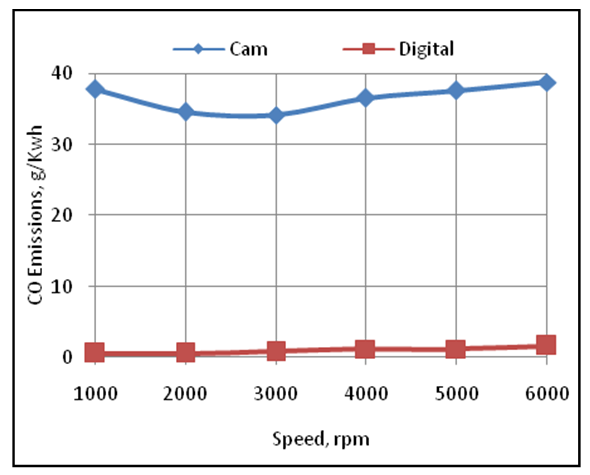 | Figure 5. Effect of Speed on the CO Emissions Produced by the Engine with Cam and Follower and Digital Valve Activating Mechanisms |
4.6. The Effect of Speed on the HC Emissions Produced by the Engine with Digital and Cam Based Valve Mechanism Design
The Fig. 6 below shows the effect of engine speed on the HC emissions produced by the engine.It is seen that the digital valve activating based engine produces lower HC emissions as compared to the cam and follower based engine design. This is because the charge motion, mixture preparation and therefore combustion is better with the digital valve type of engine design. 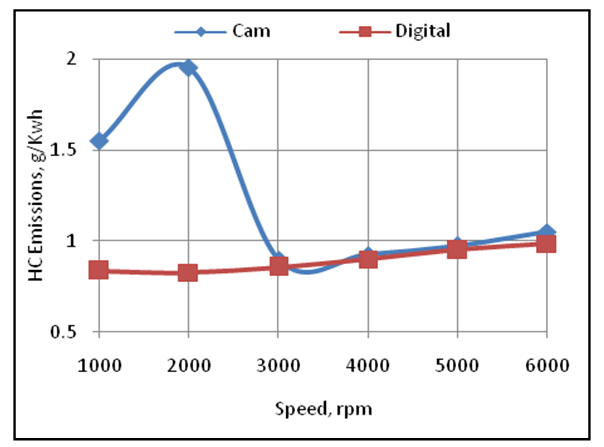 | Figure 6. Effect of Speed on the HC Emissions of the Engine with Cam and Follower and Digital Valve Activating Mechanisms |
4.7. The Effect of Speed on the NOX Emissions Produced by the Engine with Digital and Cam Based Valve Mechanism Design
The Fig. 7 below shows the effect of engine speed on the NOX emissions produced by the engine with digital valves design and cam and follower type of engine design. It is seen that the NOX emissions produced by the engine are higher at higher engine speeds. This is due to higher temperatures produced by the engine at higher engine speeds.Further the NOX emissions produced by the engine with digital valves are higher as compared to cam and follower type of engine design. This is because the volumetric efficiency and therefore the mass of air induced per cycle is higher with digital valve type of engine design. Moreover the temperatures produced with digital valve design are higher than the temperature produced with the cam and follower type of engine design which helps in the formation of NOX emissions.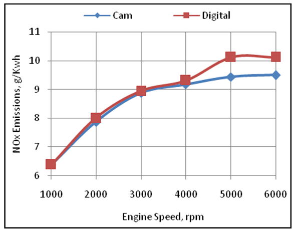 | Figure 7. Effect of Engine Speed on the NOx Emissions Produced by the Engine with Cam and Follower and Digital Valve Activating Mechanisms |
5. Conclusions
1. The digital valve mechanism improves the volumetric efficiency of the engine. the maximum improvement in the volumetric efficiency of the engine was 15.65% at the engine speed of 6000rpm.2. The digital valve mechanism improves the power, torque and reduces the fuel consumption of the engine. The maximum increase in power and torque was 25.39% and 24.75% respectively whereas the maximum fall in BSFC was 7.89% at the engine speed of 6000rpm. 3. The digital valve mechanism reduces the CO and HC emissions of the engine. The maximum reduction in CO and HC emissions were 95.7% and 57.69% respectively at the engine speed of 6000rpm.4. The digital valve mechanism design can further help in the design of VVT engines as it is controlled by micro-controllers.
ACKNOWLEDGEMENTS
Author is thankful to AVL Austria and its unit AVL India Ltd Gurgaon for providing BOOST thermodynamic engine simulation software with free license for academic research purposes.
Appendix-A
Nomenclaturea = speed of soundC = vector of source termscV = specific heat at constant volumecp = specific heat at constant pressureD = pipe diametereo = specific stagnation internal energyf = wall friction coefficientF = vector in x directionF = element in vector Fho = specific stagnation enthalpyk = ratio of specific heatsp = static pressureP0 = stagnation pressureq = wall heat flowt = time T = temperatureT0 = stagnation temperaturee = specific internal energyu = flow velocityV = cell volume (A.dx)W = vector of convective fluxesρ = densityΔt = time stepΔx= cell lengthTable 1. [13]
 |
| |
|
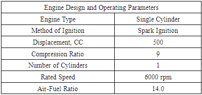
Table 2. [1]
 |
| |
|
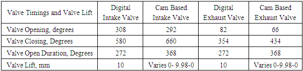
Table 3. Valve Timings and Valve Lift
 |
| |
|
References
| [1] | Heywood John B., “Fundamentals of internal combustion engines” McGraw Hill International, 1989. |
| [2] | Wayland A. Tenkku, “Solenoid Operated Cartridge Valves” SAE Technical Paper 770734, 1977. |
| [3] | Cole, C., Sturman, O., and Giordano, D., “Application of Digital Valve Technology to Diesel Fuel Injection” SAE Technical Paper 1999-01-0196, 1999. |
| [4] | Asano, M., Hosaka, A., Tominaga, T., and Ezoe, M., “Digital Engine Controller”, SAE Technical Paper 800825, 1980. |
| [5] | Morel, T., Silvestri, J., Goerg, K., and Jebasinski, R., "Modeling of Engine Exhaust Acoustics", SAE Technical Paper 1999-01-1665, 1999. |
| [6] | Maftouni, N., Ebrahimi, R., and Hossein pour, S., "The effect of Intake Manifold Runners Length on the Volumetric Efficiency by 3-D CFD Model" SAE Technical Paper 2006-32-0118, 2006. |
| [7] | Pai, D., Singh, H., and Muhammad, P., "Simulation Based Approach for Optimization of Intake Manifold", SAE Technical Paper 2011-26-0074, 2011. |
| [8] | Testa, F., Gagliardi, V., Ferrai, M., Fontanesi, S., et al., "Guidelines for the Optimization of a Muffler in a Small Two Stroke Engine", SAE Technical Paper 2016-32-0050, 2016. |
| [9] | Fortunato, F., Quadrini, F., and Bova, S., "Catalyst Light-off Evaluation Using CFD Simulation of the Exhaust Manifold", SAE Technical Paper 2005-01-3895, 2005. |
| [10] | Nanni, D., Rossi, R., Tarabusi, S., and Di Piazza, S., "Experimental Validation of a CFD Model to Predict Performance of a Motorcycle Silencer", SAE Technical Paper 2008-01-0897, 2008. |
| [11] | Winterbone DE and RJ Pearson,” Design Techniques for Engine Manifolds”, SAE International USA, 1999. |
| [12] | Winterbone DE and RJ Pearson,” Theory of Engine Manifold Design”, Professional Engineering Publishing Ltd, UK, 2000. |
| [13] | AVL LIST Gmbh, AVL BOOST Theory, Version 2009. 1. |

 Abstract
 Reference
 Full-Text PDF
 Full-text HTML