M. Marouf Wani
Mechanical Engineering Department, National Institute of Technology, J&K, Srinagar, India
Correspondence to: M. Marouf Wani, Mechanical Engineering Department, National Institute of Technology, J&K, Srinagar, India.
| Email: |  |
Copyright © 2020 The Author(s). Published by Scientific & Academic Publishing.
This work is licensed under the Creative Commons Attribution International License (CC BY).
http://creativecommons.org/licenses/by/4.0/

Abstract
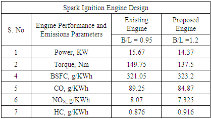
This Paper presents the computational investigations on the possible conversion of a high thermal efficiency engine into a low emissions engine by optimization using its bore to stroke ratio. The results were computed in a professional thermodynamic internal combustion engine simulation software, AVL BOOST. The software is designed using the conservations laws of mass, energy and momentum. The research investigations were done under variable bore to stroke ratio and results were computed for engine performance parameters like power, torque and brake specific fuel consumption. Results were also computed for the CO, HC, NOX emissions produced by the engine under same design and operating conditions.It was found that by varying the cylinder bore to stroke ratio the engine performance parameters as well as the emissions characteristics were changed. It was observed that the existing engine having a bore to stroke ratio of 0.95 has been designed on the basis of minimum fuel consumption or maximum thermal efficiency. The existing engine produces a reasonable output of power and torque. The CO and NOX emissions with the existing engine design are high however the HC emissions are almost minimum. It was finally observed that it is possible to design the same engine for minimum CO and NOX emissions, as needed by the demand in the market, by using a bore-stroke ratio of 1.2 at design and manufacturing level. However the HC emissions are higher with this bore to stroke ratio.
Keywords:
Engine, Spark Ignition, Bore to Stroke Ratio, Thermodynamic Design Performance and Emissions
Cite this paper: M. Marouf Wani, Research Investigations on the Conversion of a High Thermal Efficiency Engine into a Low Emissions Engine by Changing Its Bore to Stroke Ratio, Energy and Power, Vol. 10 No. 3, 2020, pp. 49-56. doi: 10.5923/j.ep.20201003.01.
1. Introduction
The research and development in the field of Internal Combustion Engines is nowadays governed by the emissions regulations revised by the authorities at regular intervals of time.The Bore to stroke ratio varies from 0.8 to 1.2 for small and medium size engines, decreases to about 0.5 for large slow speed CI engines. [1]For any given cylinder displacement volume a theoretically infinite number range of bore-to-stroke ratios could be chosen. For the same cylinder displacement, a larger bore, shorter stroke engine has a higher surface-to-volume ratio and thus greater heat rejection to the cooling system. Again for a given desired engine speed, as the stroke is made longer, the piston must travel further during each stroke and thus move faster. This increases friction, wear and inertia forces. A maximum mean piston speed is one of the structural limits imposed on any engine design. As bore diameter is increased, the intake and exhaust valves can be made larger and less restrictive. Engine breathing improves, providing a power output and thermal efficiency advantage. Again the combustion chambers of both diesel and spark ignition engines becomes more difficult to optimize as bore diameter increases. In the spark ignition engines, the challenge is one of flame travel length – the distance the flame must travel as it traverses from the spark plug across the cylinder increases with increasing bore diameter. In the diesel engine, the larger bore results in shallower combustion chamber and a greater possibility for fuel injection spray impingement on the piston surface. A larger bore also results in a greater crevice volume above top ring of the piston. The effect of increased crevice volume on hydrocarbon emissions is especially important in spark-ignition engines, but must be considered in diesel engines as well. [2]The bore-stroke ratios for petrol engines vary from square at 1.0 to over-square at 1.3, with some racing engines going above 2.0. The diesel engine on the other hand, has bore-stroke ratios that range in the opposite direction to under-square. [3]It is observed that the bore-stroke ratios for petrol engines vary from square at 1.0 to over-square at 1.3. The diesel engine on the other hand, has bore-stroke ratios which range in the opposite direction to under-square reflecting the necessity for suitable proportioning of the smaller combustion chamber of that higher compression ratio power unit. [4]The stroke to bore ratio for various engines can range from 0.6 to 1.4:1. Over square engines are more suitable for gasoline passenger cars, whereas under square engines are better utilized for large diesel engines. Thus a long-stroke to bore ratio produces a smaller surface-to-volume ratio than a short stroke-to-bore ratio engine. consequently, long-stroke engines are preferred to minimize heat losses and the formation of hydrocarbon, as opposed to short-stroke large-diameter cylinders. However peak cylinder pressure tends to decrease as the stroke-to-bore ratio becomes more under square. [5]Xiao Qin et.al., conducted a numerical investigation into the effect of stroke-to-bore (S/B) ratio on the combustion performance of a lean burn heavy-duty gaseous spark-ignited engine. The S/B ratio was varied from 0.94 to 1.32 by changing the stroke length for a fixed bore and connecting rod length. Identical cylinder head and valve events were used throughout the analysis. The compression ratio was kept unchanged by scaling the volume of the piston bowl while keeping the piston squish areas and head volume constant. FLUENT was used to conduct 3-dimensional transient flow analysis of the intake process. A Cummins modified version of KIVA-3V utilizing a G-Equation combustion model was employed to conduct simulation of the combustion process. The intake processes predicted by FLUENT were mapped to KIVA-3V at the time of intake valve closing. Both FLUENT and KIVA simulations were validated with experimental results at S/B ratio of 1.2. Simulations were also conducted at various engine speeds for different S/B ratios. The following were the observed conclusions: (1) The S/B ratio has a significant effect on turbulence intensity during the intake stroke and thus affects the in-cylinder peak pressure, heat release rates, power, and NOx emissions. (2) The gross indicated mean effective pressure and fuel specific NOx emission increase with increase of S/B ratio and decrease with increase of engine speed. (3) The gross indicated specific fuel consumption and burn duration (in crank angle) decrease with increasing S/B ratio and increase with increasing engine speed. (4) In general, a larger S/B ratio leads to higher thermal efficiency through faster combustion, and better fuel economy can be achieved for a long-stroke engine at low engine speeds. The primary influences with S/B ratio observed at constant spark timing are valid also when spark timing is modified to achieve the same centroid of heat release rates. [6]J.Benajes et.al., conducted CFD research investigations on a 4-cylinder 4-stroke High Speed Direct Injection (HSDI) CI engine to study the impact of bore-to-stroke on engine performance. The methodology involved the division of research investigations in two parts, the first part is focused on one operating point and presents a detailed description of the main effects of different B/S ratios configurations, and the second part compares the results with different engine operating conditions. For both parts the air management, injection settings and compression ratio were kept constant in order to isolate the impact of the B/S ratio.The results showed that the thermal efficiency increases with smaller B/S ratio due to lower heat losses, the NOx emissions were higher for lower B/S ratio mainly due to faster mixing and combustion, Lower B/S ratio decreases fuel rich pockets in squish region which resulted in the reduction of soot formation. [7]Elena Severi et.al., conducted CFD-3D research investigations on a V8 GDI turbocharged sporting engine as a reference in order to define the most suitable bore-to-stroke ratio for downsizing the engine while achieving the same peak power target. Both the engine boost and spark advance were adjusted until the knock safety margin of the original engine was met. On this basis, bore was reduced by 11% at constant stroke, thus obtaining a reduction of about 20% on the engine displacement. The results showed that with the beneficial effects of bore reduction on flame propagation and knock inception, the virtual engine is able to achieve the same peak power and low-end torque of the original one. [8] Jing Li et.al., conducted numerical research investigations on the effects of effective compression ratio in a gasoline and biodiesel fueled reactivity-controlled compression ignition (RCCI) engine. Simulations were conducted via coupled KIVA4-CHEMKIN code. A multi-component reaction mechanism was used to mimic the combustion process of gasoline and biodiesel. The effective compression ratios were kept at 13.71, 14.19, 14.62, 15.02 and 15.37 by varying either intake valve closing timing or stroke lengths. The combustion characteristics and NO emission were compared under different cases. The results reveal that increasing effective compression ratio contributes to larger stroke, shorter ignition delay and therefore a higher peak pressure as a result of enhanced energy release. This however results in more NO emissions. [9]K. J. Fleck conducted tests on two series of diesel engines. The first group, consisting of four engines, had the stroke changed only, while the second group had the stroke to bore ratio changed and the displacement held constant. Results of the tests indicate that the longer stroke engines had more power, higher torque, and lower fuel consumption. Friction was high for the short-stroke engines at low speeds and for the longest stroke engine at high speeds. Theoretical analysis indicates that the optimum stroke to bore ratio for best performance may vary as the compression ratio and bore diameter are changed. [10]Ziao Qin et.al., conducted numerical investigations into the effect of stroke-to-bore (S/B) ratio on the combustion performance of a lean burn heavy-duty gaseous spark-ignited engine. The S/B ratio was varied from 0.94 to 1.32 by changing the stroke length for a fixed bore and connecting rod length. Identical cylinder head and valve events were used throughout the analysis. The compression ratio was kept unchanged by scaling the volume of the piston bowl while keeping the piston squish areas and head volume constant. FLUENT was used to conduct 3-dimensional transient flow analysis of the intake process. A Cummins modified version of KIVA-3V utilizing a G-Equation combustion model was employed to conduct simulation of the combustion process. The intake processes predicted by FLUENT were mapped to KIVA-3V at the time of intake valve closing. Both FLUENT and KIVA simulations were validated with experimental results at S/B ratio of 1.2. Simulations were also conducted at various engine speeds for different S/B ratios. When ignited at the same spark timing, the most important observations are: (1) The S/B ratio has a significant effect on turbulence intensity during the intake stroke and thus affects the in-cylinder peak pressure, heat release rates, power, and NOx emissions. (2) The gross indicated mean effective pressure and fuel specific NOx emission increase with increase of S/B ratio and decrease with increase of engine speed. (3) The gross indicated specific fuel consumption and burn duration (in crank angle) decrease with increasing S/B ratio and increase with increasing engine speed. (4) In general, a larger S/B ratio leads to higher thermal efficiency through faster combustion, and better fuel economy can be achieved for a long-stroke engine at low engine speeds. [11]Jue Li et.al., investigated the effects of engine bore size on diesel engine performance and combustion characteristics, including in-cylinder pressure, ignition delay, burn duration, and fuel conversion efficiency, using experiments between two diesel engines of different bore sizes. Although most of this diagnosis is done with experimental results, a one-dimensional model is also used to calculate turbulence intensities with respect to geometric factors.The results show that the larger bore engine has a higher indicated efficiency than the smaller displaced engine. [12]
2. State of the Art Analysis
It is clear from the literature survey that most of the people have investigated the effect of bore to stroke ratio for engine power boosting, engine downsizing and improving the thermal efficiency of the engines. However the current demand in the field of commercial internal combustion engines is focused on minimizing the emissions. Most of the people have facilities to try external methods like a catalyst, exhaust gas recirculation, spark timing and micro-controller based air-fuel ratio control to minimize the emissions from the engines. Experimental facilities to carry out research with variable bore to stroke ratio is not available with most of the people at academic research level. The author has therefore tried to investigate the effect of variable bore to stroke ratio for emissions reduction using the thermodynamic simulation software.
3. Theoretical Basis [13]
3.1. The Cylinder, High Pressure Cycle, Basic Equation
The calculation of the high pressure cycle of an internal combustion engine is based on the first law of thermodynamics: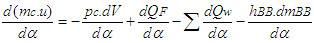 | (1) |
where = change of the internal energy in the cylinder.
 = piston work.
 = fuel heat input.
 = wall heat losses
 = enthalpy flow due to blow-by
 = blow-by mass flowIn order to solve the above equation, models for the combustion process and the wall heat transfer, as well as the gas properties as a function of pressure, temperature, and gas composition are required together with the gas equation
 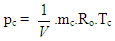 | (2) |
3.2. Combustion Model
Heat Release Approach - Vibe Two ZoneThe rate of heat release and mass fraction burned is specified by the Vibe function given by equation below.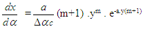 | (3) |
 | (4) |
 | (5) |
The integral of the vibe function gives the fraction of the fuel mass which was burned since the start of combustion: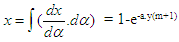 | (6) |
3.3. Heat Transfer
The heat transfer to the walls of the combustion chamber, i.e. the cylinder head, the piston, and the cylinder liner, is calculated from: | (7) |
For the calculation of the heat transfer coefficient, the Woschni 1978 heat transfer model is used.
3.4. Pipe Flow
The numerical FVM based one dimensional gas dynamics in a pipe are described by the continuity equation  | (8) |
the equation for the conservation of momentum | (9) |
and by the energy equation | (10) |
The wall friction force can be determined from the wall friction factor  :
: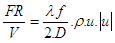 | (11) |
Using the Reynold’s analogy, the wall heat flow in the pipe can be calculated from the friction force and the difference between wall temperature and gas temperature: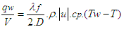 | (12) |
The parameter B/L ratio used to simulate the results suitable for minimizing the emissions from the spark ignition engine gets incorporated in the equations for the heat transfer model and therefore the first law of thermodynamics used in the full cycle simulation for the engine under consideration.
4. Results and Discussions
4.1. Engine Performance Parameters
4.1.1. Effect of Bore to Stroke Ratio on the Power Developed by the Engine
The Fig.1 below gives the effect of bore to stroke ratio on the power developed by the engine. It is seen from the graph that the power developed by the engine varies by changing the bore to stroke ratio of the engine cylinder.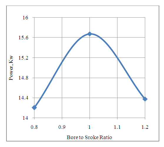 | Figure 1. Effect of Bore to Stroke Ratio on The Power Developed By The Engine |
The drop in the power developed by the engine by increasing the B/L ratio beyond 1.0 is due to a greater heat rejection to the cooling system. This is because a larger bore to stroke ratio increases the surface to volume ratio of the engine which makes a larger heat transfer area available for the heat transfer to the coolant. By using the B/L ratio of lesser than 1.0 the power developed by the engine decreases due to a drop in its combustion efficiency. This is because the deeper combustion chambers are less suitable for the flame propagation with larger axial dimension. It is seen from the graph that the engine produces a maximum power of 15.67KW with the bore to stroke ratio of 1.0.
4.1.2. Effect of Bore to Stroke Ratio on the Torque Developed by the Engine
The Fig.2 below gives the effect of bore to stroke ratio on the torque developed by the engine. It is seen from the graph that the torque developed by the engine varies by changing the bore to stroke ratio of the engine. 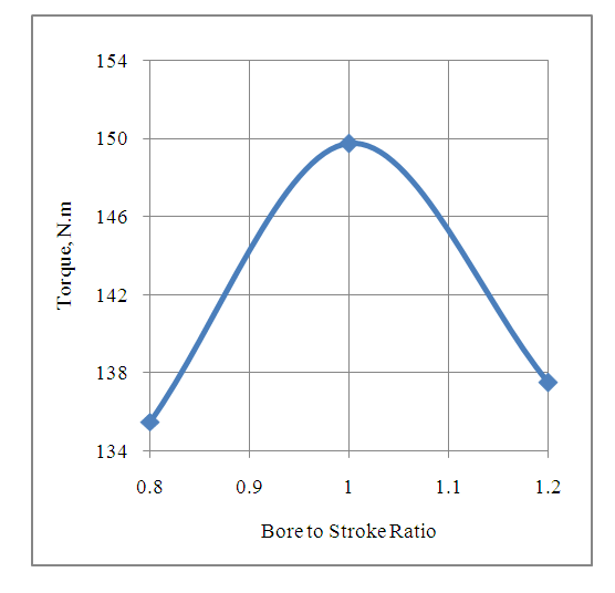 | Figure 2. Effect of Bore to Stroke Ratio on The Torque Developed by The Engine |
A B/L ratio of more than 1.0 increases the ratio of surface area to volume of the engine cylinder. A larger surface area in-turn increases the heat transfer across the engine combustion chamber. This decreases the peak cylinder pressure developed in the engine which decreases the torque developed by the engine.A B/L ratio of lesser than 1.0 reduces the torque developed by the engine due to lower combustion efficiency with deeper combustion chamber with cylindrical coordinates. This is verified by the higher HC emissions and lower CO emissions with B/L ratio equal to 0.8. Further it is seen that the engine produces a maximum torque of 149.75 Nm with the bore to stroke ratio of 1.0.
4.1.3. Effect of Bore to Stroke Ratio on the Brake Specific Fuel Consumption (BSFC) of the Engine
The Fig.3 below gives the effect of bore to stroke ratio on the brake specific fuel consumption of the engine. It is seen from the graph that the brake specific fuel consumption of the engine varies by changing the bore to stroke ratio of the engine cylinder.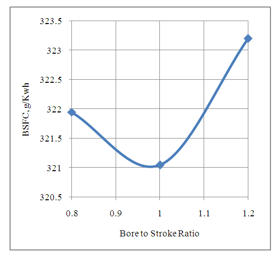 | Figure 3. Effect of Bore to Stroke Ratio on Brake Specific Fuel Consumption Of The Engine |
The increase in the brake specific fuel consumption of the engine by increasing the bore to stroke ratio of the cylinder beyond 0.98 is due to a greater heat loss from the engine combustion chamber. This is due to higher surface to volume ratio under these conditions. The increase in the brake specific fuel consumption of the engine with B/L ratio lower than 0.98 the combustion efficiency drops down. This is because the increased axial and decreased radial dimensions are less suitable for the flame propagation in the time interval for one complete cycle. This is further verified by the increased HC emissions and reduced CO emissions with this type of cylinder design.Further the engine achieves a least fuel consumption per unit energy output of 321.05 g/KWh with the bore to stroke ratio of 0.98.
4.2. Engine Emissions Characteristics
4.2.1. Effect of Bore to Stroke Ratio on the CO Emissions Produced by the Engine
The Fig.4 below gives the effect of bore to stroke ratio on the CO emissions produced by the engine. It is seen from the graph that the CO emissions produced by the engine vary by changing the bore to stroke ratio of the engine cylinder.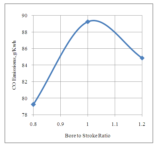 | Figure 4. Effect of Bore to Stroke Ratio on The CO Emissions Produced By the Engine |
An engine cylinder designed with a bore to stroke ratio of more than 1.02 results in an increase in the ratio of areas across the intake port of the engine. This decreases the magnitude of the reflected pressure wave at the intake port and increases the net magnitude of the forward moving wave after superposition. This in turn increases the volumetric efficiency of the engine. The increase in the volumetric efficiency of the engine improves the combustion efficiency which in turn decreases the CO emissions produced by the engine.Similarly an engine cylinder designed with the bore to stroke ratio of lesser than 1.02 decreases the CO emissions produced by the engine. This is due to a drop in combustion efficiency with reduced bore to stroke ratio. This is further clarified by an increase in the HC emissions from the engine with the reduced B/L ratio based cylindrical coordinates. It is further seen that the engine produces minimum CO emissions of 84.87 g/KWh with a bore to stroke ratio of 1.2.
4.2.2. Effect of Bore to Stroke Ratio on the HC Emissions Produced by the Engine
The Fig.5 below shows the effect of bore to stroke ratio on the HC emissions produced by the engine. It is seen from the graph that the HC emissions produced by the engine vary by changing the dimensions of the cylinders based on B/L ratio.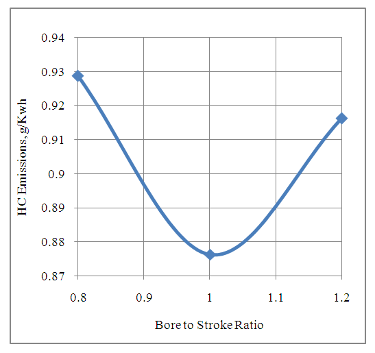 | Figure 5. Effect of Bore to Stroke Ratio on The HC Emissions Produced By The Engine |
By increasing the bore to stroke ratio beyond 1.0 the crevice volume above the piston ring for each engine cylinder increases. A larger B/L ratio based design creates larger crevice volume between the piston and cylinder. This crevice volume accommodates more hydrocarbon and air mixture. The flame front is not able to cover the crevice volume based hydrocarbons during combustion process under high pressure conditions. However during the low pressure exhaust process the gases in the crevice volumes expand and flow out of the engine cylinder under a push from the piston. Since a larger crevice volume accommodates more hydrocarbons so more HC emissions are produced with a larger bore to stroke ratio. By selecting the bore to stroke ratio lower than 1.0 the HC emissions increase because of lower combustion efficiency with cylindrical coordinate system based deeper combustion chambers.It is further observed that the engine produces least HC emissions with the bore to stroke ratio of 0.87 g/KWh with the bore to stroke ratio of 1.0.
4.2.3. Effect of Bore to Stroke Ratio on the NOX Emissions Produced by the Engine
The Fig.6 below shows the effect of bore to stroke ratio on the NOX emissions produced by the engine. It is seen from the graph that if the NOX emissions produced by the engine vary with bore to stroke ratio of the engine cylinder and is maximum at the B/L ratio of 1.0.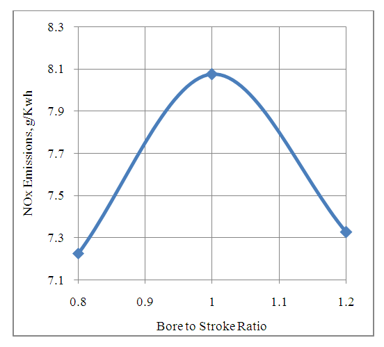 | Figure 6. Effect of Bore to Stroke Ratio on The NOx Emissions Produced By The Engine |
A B/L ratio of more than 1.0 increases the heat transfer from the engine cylinder to the coolant due to larger heat transfer area available. This decreases the peak temperatures developed in the engine cylinder which in turn decreases the NOX emissions produced by the engine.Similarly a B/L ratio of less than 1.0 decreases the combustion efficiency of the engine with deeper combustion chamber design. The resulting drop in the peak cylinder temperatures decreases the NOX emissions produced by the engine.
4.2.4. Table - Performance and Emissions Characteristics of the Engine
5. Conclusions
1. From the analysis of the computed results it is seen that the existing engine with the cylinder bore to stroke ratio of 0.95 has been designed on the basis of minimum fuel consumption or maximum thermal efficiency. It produces a reasonably high power and torque output. The CO and NOX emissions with the existing engine design are high. However its HC emissions are low.2. It is found from the computed results that by varying the cylinder bore to stroke ratio it is possible to change both the engine performance characteristics as well as its emissions characteristics. 3. Therefore as per the current demand in the market for engine design with reduced emissions, it is possible to bring down the CO emissions from 89.25 g/KWh to 84.87 g/KWh and NOX emissions from 8.07 g/KWh to 7.32 g/KWh if the engine cylinder bore to stroke ratio is changed from 0.95 to 1.2.4. However the HC emissions will increase from 0.876 g/KWh to 0.916 g/KWh by increasing the bore to stroke ratio from 0.95 to 1.2.
ACKNOWLEDGEMENTS
Author is thankful to AVL Austria and its unit AVL India Ltd Gurgaon for providing AVL BOOST engine simulation software with license for academic research purposes.
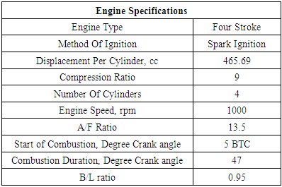
Appendix-A
Nomenclaturea = speed of sound, m/secA = pipe cross-section, m2Aeff = effective flow area, m2Ai = surface area (cylinder head, piston, liner), m2AFCP = air fuel ratio of combustion productsAgeo = geometrical flow area, m2c = mass fraction of carbon in the fuelcV = specific heat at constant volume, J/Kg.Kcp = specific heat at constant pressure, J/Kg.KCm = mean piston speed, m/secCu = circumferential velocity, m/seccu = circumferential velocity, m/secD = cylinder bore, mdmi = mass element flowing into the cylinder, kgdme = mass element flowing out of the cylinder, kgdvi = inner valve seat diameter (reference diameter), m = blow-by mass flow, kg/degree of crank anglee = piston pin offset, mE = energy content of the gas
 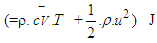 f = fraction of evaporation heat from the cylinder chargeFR = wall friction force, Nh = mass fraction of hydrogen in the fuelhBB = enthalpy of blow-by, J/Kghi = enthalpy of in-flowing mass, J/Kghe = enthalpy of the mass leaving the cylinderHu = lower heating value, J/Kgk = ratio of specific heatsl = con-rod length, mm = shape factor
 = mass flow rate, kg/secmc = mass in the cylinder, kgmev = evaporating fuel, kgmpl = mass in the plenum, kgn = mass fraction of nitrogen in the fuelo = mass fraction of oxygen in the fuelp = static pressure, barP01 = upstream stagnation pressure, barPc,o = cylinder pressure of the motored engine,barPc,1 = pressure in the cylinder at IVC, barppl = pressure in the plenum, barpc = cylinder pressure, barp2 = downstream static pressure, barqev = evaporation heat of the fuel, J/kgqw = wall heat flow, JQ = total fuel heat input, JQF = fuel energy, JQwi= wall heat flow (cylinder head, piston, liner), Jr = crank radius, mR0 = gas constant, J/mol.Ks = piston distance from TDC, mt = time, secT = temperature, KTc,1= temperature in the cylinder at intake valve closing (IVC), KTc = gas temperature in the cylinder, KTwi = wall temperature (cylinder head, piston, liner), KTL = liner temperature, KT L,TDC = liner temperature at TDC position, KT L,BDC = liner temperature at BDC position, KTw = pipe wall temperature, KT01= upstream stagnation temperature, Ku = specific internal energy, J/Kgu = flow velocity, m/secV = cylinder volume, m3V = cell volume (A.dx), m3VD = displacement per cylinder, m3w = mass fraction of water in the fuelx = relative stroke (actual piston position related to full stroke)α = crank angle, degreesαo= start of combustion, crank angle degreesΔαc= combustion duration, crank angle degreesαw = heat transfer coefficient, J/m2.Kρ = density, kg/m3μσ = flow coefficient of the portψ = crank angle between vertical crank position and piston TDC position, degrees
 = wall friction coefficientΔt = time step, secΔx= cell length, m
Appendix-B
Appendix-C
Physical And Chemical Properties Of Petrol [14]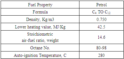
References
| [1] | John B. Heywood,” Internal Combustion Engine Fundamentals”, McGraw HILL Book Company, 1989. |
| [2] | Kevin L. Hoag,” Vehicular Engine Design”, SAE International, USA. |
| [3] | Gordon P Blair,” Design and Simulation of Four Stroke Engines”, SAE International, USA. |
| [4] | Gordon P Blair,“ Design and Simulation of Two Stroke Engines”, SAE International, USA. |
| [5] | Yushu Wang, “ Introduction to Engine Valve Trains”, SAE International, USA. |
| [6] | Xiao Qin, Francois Ntone, Leon LaPointe, Edward J. Lyford-Pike,” The Effect of Stroke-to-Bore Ratio on Combustion Performance of a Lean Burn Heavy-Duty Gaseous SI Engine”, ASME Paper No: ICEF2010-35108, pp. 801-810; 2011. |
| [7] | J.Benajes, R.Novella, J.M. Pastor, A.Hernández-López, T.Duverger, “A computational analysis of the impact of bore-to-stroke ratio on emissions and efficiency of a HSDI engine”, Elsevier Journal of Applied Energy, Volume 205, Pages 903-910, November 2017. |
| [8] | Elena Severi, Alessandrod Adamo, Fabio Berni, Sebastiano Breda, MattiaLugli and Enrico Mattarelli, “Numerical Investigation on the Effects of Bore Reduction in a High Performance Turbocharged GDI Engine. 3D Investigation of Knock“, Elsevier Energy Procedia 81 Pages 846 – 855, 2015. |
| [9] | Jing Li, Xiang Linga, Dezhi Zhoub and Wenming Yangb, “Effects of effective compression ratio by modifying IVC timing and stroke length in a reactivity-controlled compression ignition engine”, Elsevier Energy Procedia, Volume 158, Pages 1491-1496, February 2019. |
| [10] | Fleck, K. J., "some effects of stroke and bore on diesel-engine performance," SAE Technical Paper 570048, 1957. |
| [11] | Xiao Qin, Francois Ntone, Leon LaPointe, Edward J. Lyford-Pike, “The Effect of Stroke-to-Bore Ratio on Combustion Performance of a Lean Burn Heavy-Duty Gaseous SI Engine”, ASME Proceedings of The ICEF, Paper No: ICEF2010-35108, pp. 801-810; January 2011. |
| [12] | Jue Li, Timothy J. Jacobs, Tushar Bera, Michael A. Parkes, “Comparison of Diesel Engine Efficiency and Combustion Characteristics Between Different Bore Engines Author and Article Information”, ASME J. Eng. Gas Turbines Power. Oct 2018, 140(10): 102807, June, 2018. |
| [13] | AVL LIST Gmbh, AVL BOOST Theory, Version 2009.1. |
| [14] | Richard Bechtold, “Alternative Fuels”, SAE International, USA. |

 Abstract
 Reference
 Full-Text PDF
 Full-text HTML