-
Paper Information
- Next Paper
- Paper Submission
-
Journal Information
- About This Journal
- Editorial Board
- Current Issue
- Archive
- Author Guidelines
- Contact Us
Energy and Power
p-ISSN: 2163-159X e-ISSN: 2163-1603
2020; 10(2): 31-39
doi:10.5923/j.ep.20201002.02

Digital Intake Valve Based CFD Investigations of a Single Cylinder Spark Ignition Engine to Improve Its Performance and Emissions Characteristics
 Abstract
 Reference
 Full-Text PDF
 Full-text HTML
M. Marouf Wani
Mechanical Engineering Department, National Institute of Technology, J&K, Srinagar, India
Correspondence to: M. Marouf Wani, Mechanical Engineering Department, National Institute of Technology, J&K, Srinagar, India.
| Email: |  |
Copyright © 2020 The Author(s). Published by Scientific & Academic Publishing.
This work is licensed under the Creative Commons Attribution International License (CC BY).
http://creativecommons.org/licenses/by/4.0/

This paper presents the results of the CFD research investigations on a single cylinder spark ignition engine modeled alternatively with a digital intake valve and a cam based intake valve. The results were computed in the thermodynamic simulation software AVL BOOST. The software uses the finite volume method along with the conservation equations of mass, momentum, energy and the equation of state for an ideal gas. The parameters computed were pressure, velocity, density and temperature etc. The emissions and performance parameters of the engine were simulated for both the conventional cam based valve and the digital valve. The digital intake valve was modeled for a constant maximum valve lift throughout the intake process where as the conventional cam based valve was modeled for variable valve lift on a crank angle to crank angle basis. The results showed that the engine with the digital intake valve gave better volumetric efficiency, power, torque and brake specific fuel consumption as compared to the engine using the conventional cam based valve. Further the engine with digital intake valve has better emissions characteristics as compared to the engine with cam based valve.
Keywords: Engine, Spark Ignition, Intake Manifold, Digital Valve, CFD, Volumetric Efficiency, Numerical Method, Performance and Emissions
Cite this paper: M. Marouf Wani, Digital Intake Valve Based CFD Investigations of a Single Cylinder Spark Ignition Engine to Improve Its Performance and Emissions Characteristics, Energy and Power, Vol. 10 No. 2, 2020, pp. 31-39. doi: 10.5923/j.ep.20201002.02.
Article Outline
1. Introduction
- The computational fluid dynamic investigations are used to predict the thermodynamic and gas dynamic behavior of the components of the intake and exhaust gas manifolds of an internal combustion engines. The design of the intake manifold of an internal combustion engine effects the engine performance parameters like volumetric efficiency, power, torque, brake specific fuel consumption and its emissions characteristics. The design of the exhaust gas manifold involves the catalyst type components related to emission control from I C engines, mufflers related to noise reduction, EGR system based pipe connections for reducing the NOx emissions from engines, The addition of turbochargers in the gas exchange system of an internal combustion engine, for boosting the power of the engine or alternatively downsizing the engine, can also be optimized for best possible matching with the engine using the CFD simulations with finite volume method. John B Heywood in his book writes that two basic types of models have been developed for the processes that govern the performance and emissions of I C engines. These are categorized as thermodynamic or fluid dynamic in nature depending on whether the equations which give the model its predominant structure are based on energy conservation or on a full analysis of the fluid motion. Thermodynamic energy conservation based models are: Zero – dimensional , since in absence of any flow modeling, geometric features of the fluid motion cannot be predicted; Phenomenological, additional detail beyond the energy conservation equations is added for each phenomenon in turn; Quasi-dimensional, specific geometric features, e.g., the spark-ignition engine flame or the diesel fuel spray shapes, are added to the basic thermodynamic approach; Fluid-dynamic based models or multidimensional models, these have inherent ability to provide detailed geometric information on the flow field based on solution of the governing flow equations of conservation of mass, energy and momentum. In gas exchange processes in internal combustion engines, volumetric efficiency is used as an overall measure of the effectiveness of a four stroke cycle engine and its intake and exhaust systems as an air pumping device. Air flow constrains maximizing the engine power. lesser air flow in SI engines are obtained by restricting the intake system flow area with the throttle valve. Volumetric efficiency is affected by the fuel, engine design, and engine operating variables like fuel type, fuel/air ratio, fraction of fuel vaporized in the intake system, heat of vaporization of the fuel, mixture temperature as influenced by heat transfer, ratio of exhaust to inlet manifold pressures, compression ratio, engine speed, intake and exhaust manifold design, port design and intake and exhaust valve geometry, size, lift, and timings. [1]Morel, T., et al., conducted one-dimensional fluid dynamic simulations of the flow in the engine manifolds, exhaust and intake elements with an objective to design it both for engine performance as well as for engine acoustics. The experimental investigations that followed verified the prediction of the good results based on simulation. [2]Maftouni, N., et al conducted 3-D simulations on the intake manifold of a XU7 Engine under steady state and unsteady state operation using 3-D CFD code. The simulations were carried out with three different runner lengths of 110, 120 and 130% of the original to see its effects on the volumetric efficiency of the engine under variable speed operation. The steady state results were compared with the flow bench rig based data for validation. 1-D WAVE code was used for generating the boundary condition for unsteady state simulation. The results showed that the volumetric efficiency of the engine increases with 120% runner length. [3]Pal, D., et al., conducted simulation studies on the design of intake manifolds in order to achieve a required level of engine performance. First of all the simulations were done using 1-D CFD code to optimize various parameters of the intake manifold. A few shortlisted designs were tested experimentally which showed strong correlation with simulated results. The second series of investigations was done by using a 3D CFD code for the intake manifolds to analyze the 3D effects of the manifold geometry. The third set of simulations was carried out to tune the manifold geometry further for possible optimum dimensions by using a coupled 1D and 3D CFD code. The results showed that the simulation studies lead to a better prediction of the engine performance. The 3D CFD simulations can give the detailed information about fluid and flow properties in complex 3D domains while 1D CFD simulation can provide important information at a system level, i.e about the performance of the entire engine. The drawbacks of the two simulation methods are that the former requires high computational cost while the latter is not able to capture complex local 3D features. [4]Testa, F., et al conducted computational analysis of the unsteady flow in a single cylinder two stroke gasoline engine using advanced numerical tools. The results were validated by the experimental measurements. A STAR-CD code based 3D model was used for the entire engine. Also a GT-POWER 1D and Converge-LITE 3D codes based 1D-3D integrated fluid dynamics model was used for predicting the performance and gas-dynamics in the whole intake and exhaust systems. The results showed that the methodology accurately predicted the phenomena in whole engine. Further it was observed that the wave motion based analysis strongly affects 3D design of muffler in small two stroke engines. [5] Fortunate, F., et al conducted transient CFD investigations of the exhaust gas manifold fitted with a catalyst. The new European driving cycle, NEDC, was adopted for these transient simulations to evaluate the vehicle fuel economy and its emissions characteristics. Further the effect of the exhaust gas temperature on the catalyst light-off time were also simulated by designing manifolds with different configurations and materials. The computed results were reasonably validated by the experimental investigations. The results showed that a thin exhaust gas manifold made of steel improves the thermal light-off of the catalytic convertor as compared to a similar manifold made of thicker cast iron. [6]Nanni, D. et al., conducted experimental investigations on the silencer of a motorcycle engine to validate the CFD model simulated to predict the performance of the same. The experiments were conducted on a test bench where the mass flow rate of the exhaust gas through the silencer was measured for several inlet-outlet pressure gradients. The finite volume method based numerical data for mass flow rate was computed for the same with several mesh sizes and computational settings. The results showed that the finite-volume model is a promising method for analyzing the performance of silencers with different designs. Further the FVM model does not give 100% accurate results to predict the absolute performance of the silencers. [7]Pan, W., et.al., used CFD methodology to study the losses in the intake region involving inlet duct, plenum, ports, valves, and cylinder of a straight six cylinder diesel engine. Each cylinder was studied with its intake valves set at high, medium and low valve lifts. It was found that the total pressure losses were caused by a number of flow mechanisms including skin friction, separation, recirculation, reattachment, impingement, jet-to-jet interaction, high turbulence and swirl and tumble type of secondary flows. It was further seen that the total pressure losses in the entire intake region decreased with increasing valve lift. It was further seen that the losses within the valve clearance region decreased with increasing valve lift. [8]Guan-Jhong Wang et. al., developed a ANSYS FLUENT CFD solver based model to simulate the phenomenon during each stroke of a single cylinder diesel engine. The data for the initial conditions and the boundary conditions were taken from the experimental data obtained from a turbo-charged common-rail diesel engine developed by Mitsubishi. The variables that were observed included cylinder pressure, gas velocity, cylinder temperature, fuel particle tracks, and mass fraction of cylinder gas components. The effect of fuel injection timings on the combustion heat release process, cylinder pressure and cylinder temperature were investigated under different engine operating conditions. The pure diesel (C10H22) was used as fuel. In the FLUENT setup, k – epsilon model was used for viscous flow conditions, and the auto-ignition model was used to investigate the heterogeneous diesel engine combustion process. It was observed that the simulated results could be used to generate a flow field, such as the tumbling motion, inside the engine cylinder which can further be used to defend the experimental results. The results showed that by advancing the fuel injection timing, the various phases in combustion were also advanced, resulting in higher peak cylinder pressure and peak cylinder temperature. [9]Priesching et. al., used a numerical model, based on pre-flame reaction based combustion and knock characteristics, in a CFD network with a view to investigate how to improve efficiency, reduce fuel consumption and specific CO2 emissions. It was concluded that the CFD based model was capable of supporting the engine development process in all combustion and emission related aspects. [10]Leep, L et. al., conducted fluid dynamics simulations of the gas exchange process in a crankcase-scavenged, two stroke engine to study scavenging characteristics of the engine over the whole operating range and to investigate the effect of various design changes. The simulations used the time-dependent velocity and pressure boundary conditions in the transfer port and exhaust port respectively which were obtained from one-dimensional gas exchange code. It was seen that the bulk flow characteristics, scavenging and trapping efficiencies, computed from these simulations compared well with experimental data. [11]Matus, R., used computer simulation tool namely RAMPANT involving three dimensional, viscous, turbulent flow modeling to analyze the flow through a multiple passage exhaust gas manifold system including a catalytic convertor. The effect of flow non-uniformity on catalytic convertor was examined. It was concluded that the software can successfully analyze a wide range of flow oriented components of the engine exhaust gas manifold. [12] Zhen Lu et.al., write that the intake port flow characteristics in an internal combustion engine significantly affect its power output, fuel economy, and emissions. In order to optimize the flow characteristics in the intake port, steady flow tests on a four valve diesel engine were conducted to investigate the effect of casting and machining deviations of the intake port on the in-cylinder flow characteristics. The results showed that these deviations led to the variation of swirl ratio up to 20%. In order to understand the possible rectification of the intake port manufacturing defect, CFD simulations were also conducted. It was concluded that the design dimensions of the intake ports should have higher tolerances before casting and manufacturing processes. [13]Lei Cui et. al., write in their research paper that the design of intake port plays a critical role in the development of modern internal combustion engines. The traditional method of intake port design is time consuming, involving extensive testing and production cycles. A new 3D CFD method was used to model tangential port design. Multiple cases for the model were regenerated with different sets of structure parameters. Finally CFD was used to investigate the effect of these geometrical structural parameters on the intake port performance. The results showed that the flow capacity and the large-scale vortex intensity changed by changing the structural parameters. The structural parameters based CFD model was further applied successfully to design the intake port of a production four-valve direct-injection gasoline engine. [14] In order to improve the engine performance and its emissions characteristics, the amplitude of the reflected waves at intake valves with changing crank angle positions can be minimized to take maximum advantage of the forward or in-cylinder moving compression waves. The decrease in the amplitude of the reflected waves with proposed digital intake valve as compared to the conventional cam and follower based valve will increase the volumetric efficiency of the engine. This is turn will improve its performance parameters like power, torque and brake specific fuel consumption.
2. Theoretical Basis. [15,16]
- Conservation Equations for mass, momentum and energy in the following form are used for solving the research problems related to 1-Dimensional compressible flow of gas in a pipe.
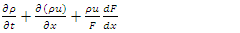 | (1) |
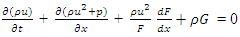 | (2) |
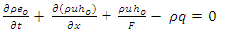 | (3) |
 | (4) |
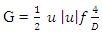
 is used to ensure that the pipe wall friction always opposes the fluid motion.The above three equations written in conservation law form can be written in symbolic vector form as
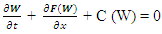 | (5) |
 | (6) |
 | (7) |
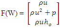 | (8) |
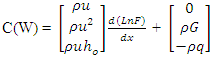 | (9) |
 | (10) |
 | (11) |
 given by
 | (12) |
 | (13) |
 | (14) |
 and
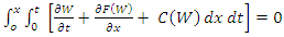
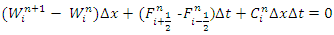
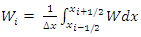
and  are the fluxes through the extreme ends of the pipe, all internal fluxes cancel out. This guarantees the integral form of the conservation equations, thereby ensuring, for example, the conservation of mass through a pipe.The finite difference methods used above when interpreted in the form of equations (10) to (12) are called conservative, finite volume schemes.
3. Methodology Used in Present Investigations
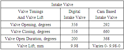
- 1. Two types of intake valve designs were modeled for the intake port of the engine under consideration during its intake process.2. First the computations were done with variable valve lift for each crank angle during the intake process as per the cam and follower based design for any conventional engine. A variable value for the coefficient of discharge at the intake port of the engine was used for this type of valve design. A maximum value was used for fully open valve and the numerical value was decreased accordingly for partially open valve for each crank angle during the intake process. 3. Next the computations were repeated with a proposed digital solenoid type intake valve having a constant lift for each crank angle during the intake process. The coefficient of discharge for the intake process was maintained constant at its peak value for this type of proposed digital valve based engine design.4. Numerical finite volume method was used for solving the equations written for control volume under consideration. The control volume is taken as a length step. The integration limits for the length steps was the length between the open end of the intake manifold and its intake port. The integration limits for the time steps corresponded to one complete cycle of the four stroke cycle engine. The integration limits for time steps were the time at the start of the cycle and the time at the end of the cycle at a particular engine speed. The central difference method of the finite difference scheme was employed for computing the values of thermodynamic properties at each node of the pipe along the flow.5. The number of length steps, for the corresponding time steps for full cycle simulation, were governed by the principle of minimization of error as per the CFL stability criterion. 6. Again as per the principles of wave propagation for a particular pipe element under consideration, the waves are reflected at the points of geometrical discontinuity along the flow in the pipe element. The geometrical discontinuity along the pipe elements basically represented a change in the medium along the flow in pipe. In order to include the effect of the reflection of waves for the time step under consideration and the forward moving wave being generated at the next time step the equations for the waves were solved as per D-Alembert’s principle. 7. The D-Alembert’s solution was used to write the wave equation for each thermodynamic variable as a vector sum of the forward moving wave and the reflected backward moving wave. 8. The properties of the atmospheric air were used as boundary conditions at the inlet or open end of intake manifold. 9. At the intake port side of the intake manifold the separate boundary conditions were used for each crank angle during the intake process for the conventional cam and follower based valve designs as per the instantaneous valve lift and corresponding flow area available. The boundary conditions at the intake port with digital intake valve were kept constant during the intake process for the proposed digital solenoid type of intake valve.
4. Results and Discussions
4.1. Effect of Intake Valve Design on the Pressure Wave at the Same Length Step of Intake Manifold of the Engine with Respect to Time Steps in Terms of Crank Angle Degrees
- The Fig.1 below shows the effect of the design of intake valve on the pressure wave generated at the same length step of intake port with respect to time steps in terms of the crank angle degrees. It is evident that the magnitude of pressure varies over the complete engine cycle.
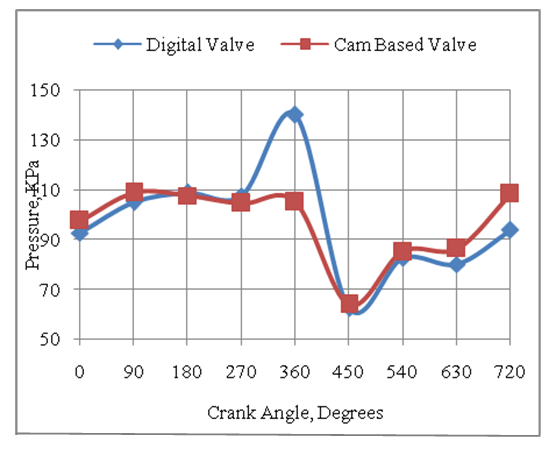 | Figure 1. Effect of Valve Design on the Pressure Wave of Air at the Same Length Step of Intake Port with Respect to Time Steps in Crank Angle |
4.2. Effect of Intake Valve Design on the Density Wave of Air at the Same Length Step in the Intake Manifold of the Engine in Terms of the Time Steps of Crank Angle
- The Fig.2 below shows the effect of the design of intake valve on the density wave generated at the same length step of intake port with respect to the time steps in terms of the crank angle degrees. It is evident that the magnitude of density varies over the complete engine cycle.
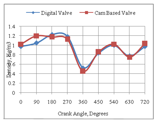 | Figure 2. Effect of Valve Design on the Density Wave of Air at the Same Length Step of Intake Port with Respect to Time Steps in Terms of Crank Angle Degrees |
4.3. Effect of Intake Valve Design on the Velocity Wave of Air at the Same Length Step in the Intake Manifold of the Engine in Terms of Time Steps of Crank Angle
- The Fig.3 below shows the effect of design of intake valve on the velocity wave generated at the same length step of intake port with respect to the time steps in terms of the crank angle degrees. It is evident that the magnitude of velocity varies over the complete engine cycle.
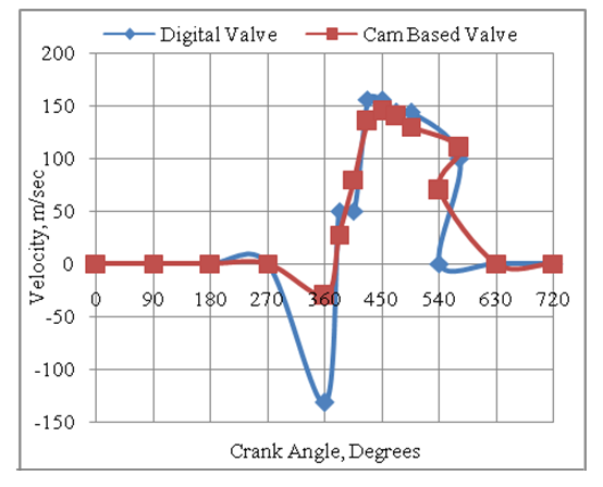 | Figure 3. Effect of Valve Design on the Velocity Wave of Air at the Same Length Step of Intake Port with Respect to the Time Step in Terms of Crank Angle Degrees |
4.4. The Effect of Speed on the Volumetric Efficiency of the Engine with Digital and Cam Based Intake Valves
- The Fig.4 below shows that the volumetric efficiency of the engine varies with speed for both digital and cam based valves. The volumetric efficiency is higher at lower engine speeds as compared to high engine speeds. However due to the combined effect of the thermodynamic and gas dynamic properties as discussed above the volumetric efficiency of the engine is higher with digital type of valve design as compared to the cam type of valve design.
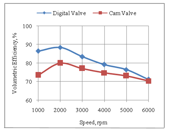 | Figure 4. Effect of Speed on Volumetric Efficiency of Engine with Digital Valve and Cam Based Valve |
4.5. The Effect of Speed on the Power Developed by the Engine with Digital and Cam Based Intake Valves
- The Fig.5 below shows that the power developed by the engine with digital intake valve is higher as compared to the engine with cam type of intake valve. This is due to the higher volumetric efficiency of the engine with the digital valve as compared to the engine with cam and follower type of valve.
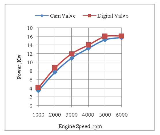 | Figure 5. Effect of Speed on Power Developed by the Engine with Digital Valve and Cam Type Valve |
4.6. The Effect of Speed on the Torque Developed by the Engine with Digital and Cam Based Intake Valves
- The Fig.6 below shows that the higher volumetric efficiency of the engine with the digital intake valve helps to develop higher torque as compared to engine with cam and follower type of valve.
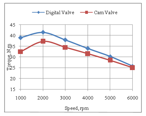 | Figure 6. Effect of Speed on the Torque Developed by the Engine with Digital Intake Valve and Cam Based Intake Valve |
4.7. The Effect of Speed on the Brake Specific Fuel Consumption of the Engine with Digital and Cam Based Intake Valves
- The Fig.7 below shows that the brake specific fuel consumption of the engine is minimum at the engine speed of 2000 rpm. This is due to better combustion resulting in higher thermal efficiency at this speed. Again due to the combined effect of higher power and higher mass flow rate of fuel with the digital valve as compared to the cam based valve the brake specific fuel consumption is lower with digital valve as compared to the cam type valve.
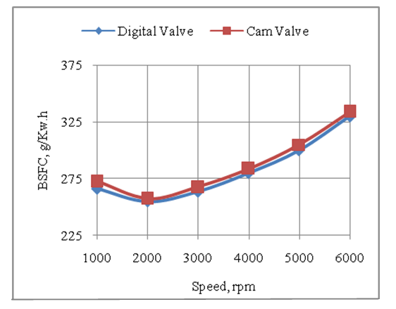 | Figure 7. Effect of Speed on Brake Specific Fuel Consumption of Engine with Digital Intake Valve and Cam Based Intake Valve |
4.8. The Effect of Speed on the CO Emissions Produced by the Engine with Digital and Cam Based Intake Valves
- The Fig.8 below shows that the CO emissions per unit of energy output with two types of intake valve designs are comparable. This is because the operating value of air-fuel ratio has been maintained constant for both the cases.
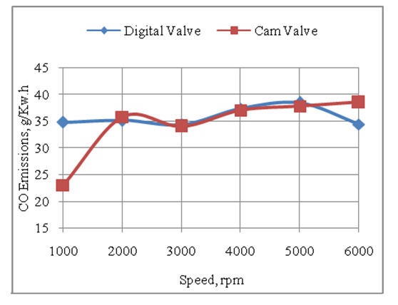 | Figure 8. Effect of Speed on CO Emissions Produced by the Engine with Digital Intake Valve and Cam Based Intake Valve |
4.9. The Effect of Speed on the HC Emissions Produced by the Engine with Digital and Cam Based Intake Valves
- The Fig.9 below shows that the HC emissions per unit of energy output with both types of valve operating mechanisms are minimum at the engine speed of 2500rpm. This is due to best possible thermal efficiency achieved at this speed.
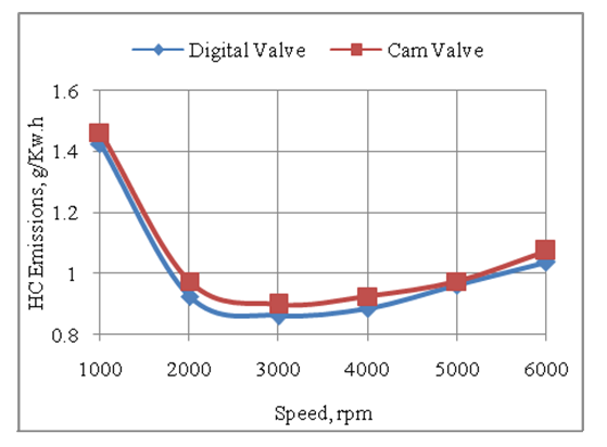 | Figure 9. Effect of Speed on HC Emissions Produced by the Engine with Digital Intake Valve and Cam Type Intake Valve |
4.10. The Effect of Speed on the NOX Emissions Produced by the Engine with Digital and Cam Based Intake Valves
- The Fig.10 below shows that the engine with cam type of intake valve produces more NOX emissions as compared to the engine with digital intake valve. This is because a drop in HC emissions with digital intake valve based engine design more oxygen gets consumed for the chemical conversion of HC during combustion process. The drop in the availability of oxygen finally decreases the NOX emissions from the engine with the digital intake valve.
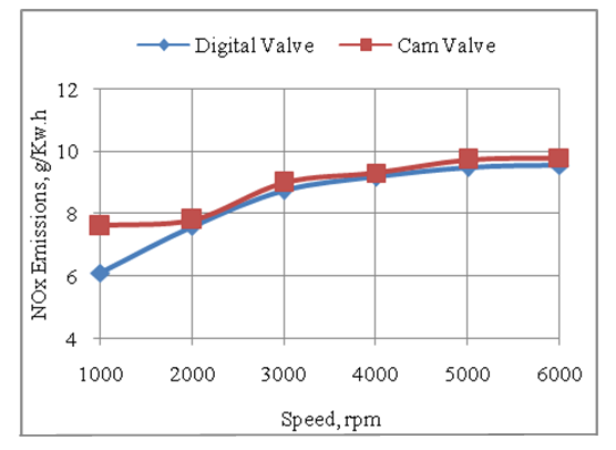 | Figure 10. Effect of Speed on NOx Emissions Produced by the Engine with Digital Intake Valve and Cam Based Intake Valve |
4.11. The Effect of Speed on the Exhaust Gas Temperature Produced by the Engine with Digital and Cam Based Intake Valves
- The Fig.11 below shows the temperature of exhaust gas produced by the engine is higher with digital intake valve type as compared to the cam and follower type of intake valve. This is because the volumetric efficiency and therefore the air and fuel consumption are higher with digital intake valve.
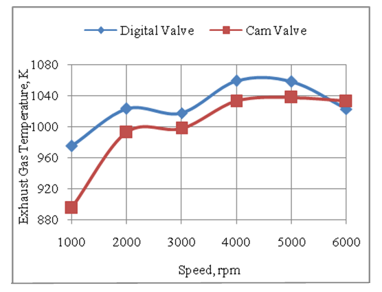 | Figure 11. Effect of Speed on the Exhaust Gas Temperature of the Engine with Digital Intake Valve and Cam Based Intake Valve |
5. Conclusions
- 1. The engine designed with a digital valve in the intake manifold has a higher volumetric efficiency.2. The power developed by the engine with digital intake valve is higher as compared to the engine with cam and follower type of intake valve.3. The torque developed by the engine with digital intake valve is higher as compared to the engine designed with cam based valve.4. The brake specific fuel consumption of the engine with digital intake valve design is lower than the engine designed with cam based valve.5. The above results indicate that the digital intake valve type of engine design has a higher thermal efficiency as compared to the engine designed with a cam and follower type of intake valve.6. It is concluded that the performance and emissions characteristics of the engine are improved by incorporating the digital type of intake valves in the reciprocating engine design.
ACKNOWLEDGEMENTS
- Author is thankful to AVL Austria and its unit AVL India Ltd Gurgaon for providing AVL BOOST thermodynamic engine simulation software with free license for academic research purposes.
Appendix-A
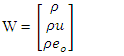
- Nomenclaturea = speed of soundC = vector of source termscV = specific heat at constant volumecp = specific heat at constant pressureD = pipe diametereo = specific stagnation internal energyf = wall friction coefficientF = vector in x directionF = element in vector Fho = specific stagnation enthalpyk = ratio of specific heatsp = static pressureP0 = stagnation pressureq = wall heat flowt = time T = temperatureT0 = stagnation temperaturee = specific internal energyu = flow velocityV = cell volume (A.dx)W = vector of convective fluxesρ = densityΔt = time stepΔx = cell length
|
|
|