M. Marouf Wani
Mechanical Engineering Department, National Institute of Technology, J&K, Srinagar, India
Correspondence to: M. Marouf Wani, Mechanical Engineering Department, National Institute of Technology, J&K, Srinagar, India.
| Email: |  |
Copyright © 2019 The Author(s). Published by Scientific & Academic Publishing.
This work is licensed under the Creative Commons Attribution International License (CC BY).
http://creativecommons.org/licenses/by/4.0/

Abstract
This paper presents the octane demand based methodology for designing a spark ignition engine for any suitable S.I engine fuel alternatively for maximum performance and minimum CO emissions. An example of designing a single cylinder 4 stroke cycle spark ignition engine alternatively for maximum performance and minimum CO emissions is given in this paper. The computational design investigations were done in the professional internal combustion engines simulation software, AVL BOOST. The design of the software is based on conservation laws for mass, momentum and energy. The software uses the numerical finite volume method to solve thermodynamic equations for computing various thermodynamic properties. The computational simulations were done to ensure that the octane demand of the engine does not exceed the octane number of any commercially available gasoline for each case of engine design. The compression ratio and spark timing based start of combustion timing of the engine were optimized to redesign the existing engine with better performance for a market need based engine with minimum CO emissions. The results showed that it was possible to redesign the existing engine with better performance for an engine with minimum CO emissions while maintaining the maximum octane demand of the engine within the octane number of the commercially available gasoline. It was also observed that engine designed for minimum CO emissions shows a drop in HC emissions as well. However there was an increase in the level of NOx emissions produced by this engine. The performance of the engine designed for minimum CO emissions was satisfactory when compared with the engine producing higher power.
Keywords:
Octane Demand, Engine, Spark Ignition, Gasoline, Octane Number, Emissions and Performance
Cite this paper: M. Marouf Wani, Octane Demand as a Criteria for Designing a Spark Ignition Engine Alternatively for Minimum CO Emissions and Maximum Power Generation, Energy and Power, Vol. 9 No. 1, 2019, pp. 27-37. doi: 10.5923/j.ep.20190901.03.
1. Introduction
Since the invention of internal combustion engines, research investigations were done continuously to improve its performance parameters by using various combinations of its design and operating parameters. With transfer of technology concept being adopted throughout the world the number of engine based vehicles used by people throughout the world has increased tremendously. The automotive industry is now faced with the challenge of manufacturing vehicles fitted with engines designed for minimum emissions formation as per the emissions standards in each country throughout the world. With the regular revisions in emissions standards towards the more strict norms, both the engine design and also the quality of the fuel supplied from refineries have to be changed accordingly. One of the constraints faced by the designers to maximize the engine performance along with its emissions characteristics is the limiting value of the octane number of commercial gasoline or petrol. Keeping this in mind only engine design and operating parameters were varied to simulate the engine design for minimum CO emissions corresponding to a maximum octane demand of 95 as available with commercial gasoline or petrol.
2. Literature Survey
In order to maximize engine performance parameters like power and torque, we need to maximize the parameters like fuel conversion efficiency, volumetric efficiency, inlet air density, fuel-air ratio that can be usefully burned in the engine, heating value of fuel, engine displacement volume and the operating speed of engine. Also the spark timing of the spark ignition engines has to been optimized corresponding to maximum brake torque, or MBT, timing which corresponds to the condition when the magnitudes of the compression stroke work transfer from piston to cylinder gases and the expansion stroke work transfer from the cylinder gases to the piston just offset each other. Further the engine design and operating parameters including the spark timing has to be chosen in such a way so that the maximum octane demand of the engine is within the octane number of the commercially available gasoline or any other spark ignition engine fuel. This will result in a spark ignition engine design with normal combustion without any possibility of knock. From the pollution formation and emissions regulations point of view, the spark ignition engine exhaust gases contain oxides of nitrogen (nitric oxide, NO, and small amounts of nitrogen dioxide, NO2 – collectively known as NOx), carbon monoxide (CO), and organic compounds which are unburned or partially burned hydrocarbons (HC). The relative amounts depend upon engine design and operating conditions but are of order: NOx, 500 to 1000 ppm or 20 g/kg fuel; CO, 1 to 2 percent or 200 g/kg fuel; and HC, 3000 ppm (as C1) or 25 g/kg fuel. Further the use of alcohol fuels in these engines substantially increases the aldehyde emissions which are not yet subject to regulation. One of the most important variables in determining spark ignition engine emissions is the fuel/air equivalence ratio. So far, the spark ignition engines have been operated close to stoichiometric or slightly fuel-rich side to ensure smooth and reliable operation. The leaner mixtures give lower emissions until the combustion quality becomes poor (and eventually misfire occurs), when HC emissions rise sharply and engine operation becomes erratic. In a cold engine, when fuel vaporization is slow, the fuel flow is increased to provide an easily combustible fuel-rich mixture in the cylinder. Thus until the engine warms up and this enrichment is removed, CO and HC emissions are high. At part load conditions, lean mixtures could be used which would produce lower HC and CO emissions and moderate NOx emissions. Use of recycled exhaust gas (EGR) to dilute the engine intake mixture lowers the NO levels, but also deteriorates the combustion quality. [1]Crawford, A et al conducted experimental investigations on a naturally aspirated port injected spark ignition engine for Ford Motor Co in association with Cosworth Technology to achieve a high performance in combination with a Euro IV capability. The results showed that in order to achieve the required torque across its speed range the volumetric efficiency needed to be maximized over the same range of speed. This was achieved by using a combination of continuously variable inlet valve timing, variable length intake manifold and a tuned exhaust gas manifold. The emissions requirements were met by minimizing the catalyst light off time. This was possible by stabilizing combustion under cold start conditions by retarding spark timing, optimizing intake port flow and tumble characteristics and using a VVT strategy. Further the use of tuned exhaust gas manifold improved the engine efficiency. To meet the emission targets the latest tri-metal coating and metal substrates were used for the catalyst. The catalyst location along the manifold was also optimized to achieve the same. Moreover an individual knock sensor technology was incorporated for each cylinder to ensure maximum performance at all times. [2]Ikeya, K. et al conducted experimental investigations on a single cylinder engine in order to improve its thermal efficiency. The methodology used involved the use of a higher stroke-bore ratio, a lower effective compression ratio and a high EGR rate. In order to overcome the slow combustion and reduced ignitability due to higher EGR rate the use of high energy ignition system and optimized combustion chamber shape with high tumble port was tried. It was observed that a brake thermal efficiency of 45% was achieved at an engine speed of 2000 rpm with a stroke-bore ratio of 1.5, a compression ratio of 17, an effective compression ratio of 12.5 and an EGR rate of above 30%. [3]Reinhart, T. et al., conducted computational investigations on a gasoline powered medium truck engine using a Dedicated EGR (D-EGR) system. The aim of the research investigations was to develop the gasoline engine based medium truck engine technology having thermal efficiency compatible to a medium duty diesel engine for Class 4 to Class 7 truck operations. The computational investigations were carried out in GT-POWER using the experimental data from a smaller size D-EGR engine. The parameters evaluated for the D-EGR engine were displacement, operating range of speed, boosting systems and BMEP levels. Further a thorough comparison between D-EGR engine, a conventional gasoline engine and a diesel engine was done by applying the fuel consumption maps of the D-EGR to two vehicle models run over a range of 8 duty cycles at 3 payloads. The results showed that the D-EGR gasoline engines can compete with medium duty diesel engines in terms of thermal efficiency and GHG emissions. However the lower heating value of gasoline as compared to diesel increases the fuel consumption of the D-EGR gasoline engine. Further the lower in-cylinder and exhaust gas temperatures developed in the D-EGR gasoline engine will result in the improved durability of these engines when compared to conventional gasoline engines. Finally, since a D-EGR gasoline engine fitted with a 3-way catalyst will be cheaper than a diesel engine fitted with a DPF and SCR technology, there is an opportunity for D-EGR gasoline engines to be used for medium truck market share. [4]Lee, B et. al conducted research investigations on improvement of thermal efficiency of gasoline engine beyond 40%. The parameters tested in the studies were compression ratio, tumble ratio, twin spark configuration, EGR rate, Intake and exhaust cam shaft duration and component friction. Effects of each parameter on fuel consumption reduction were discussed with experimental results. The results showed that the optimized best BSFC without knock was achieved at the compression ratio of 14. Also highly diluted combustion for knock mitigation was possible with high EGR rate of 35%. The use of twin spark plugs and high tumble flow resulted in faster and stable combustion under highly diluted operations. A LIVC strategy selected for cam profiles helped to mitigate knock and reduce the exhaust pulse interaction under high load. With all above mentioned optimized parametric studies a brake thermal efficiency of 42.2% was achieved under stoichiometric operation in a newly developed 2.0 L 14 NA proto-type gasoline engine. [5]Taylor, C et al., conducted experimental investigations on a single cylinder spark ignition system aeronautical-engine in the laboratory of the Massachusetts Institute of Technology with carburetor, inlet manifold injection and direct injection into the cylinder. The experiments were conducted using gasoline and fuel oil. The diesel engine type fuel injection system was used for this purpose with suitable modifications. The results showed that the engine showed better performance with either of the two fuel injection systems as compared to carburetor. In case of the in-cylinder injection the power was increased by 10 per cent and the fuel consumption was also reduced. The performance with fuel oil was restricted by its poor antiknock quality as compared to gasoline having higher octane number. However the performance with fuel oil was comparable to gasoline up to compression ratio suitable for both the fuels without knock. As compared to diesel engine application, the mechanical fuel injection system showed simpler problems with gasoline engine. Further it was possible to decrease the time for induction process because of greater volumetric efficiency with direct injection system. Also the direct injection of gasoline resulted in its almost instantaneous vaporization because of high temperatures in cylinder as compared to intake manifold at the time of fuel injection. Moreover at low throttle the fuel metering and distribution with pump based mechanical fuel injection system was better as compared to the carburetor system. [6]Herbsleb, K., et al., conducted experimental investigations with lean mixtures on a single cylinder four stroke engine. In order to overcome the drop in flame speed with lean mixtures, the compression ratio of the engine was raised to 13.8:1. This was further assisted by replacing the conventional piston top by a swirl type combustion chamber. For comparison purposes the experiments were repeated with a heron-type combustion chamber. The results showed that the minimum fuel consumption was obtained at an air-fuel ratio of 19. Further on an average basis, the swirl type combustion chamber showed 5% improvement in fuel consumption. However the peak cylinder pressure was reduced in the swirl type combustion chamber as compared to heron-type combustion chamber. [7]Nakamura, N. et al., conducted experimental investigations with lean combustion on a four cylinder engine with multipoint spark ignition system, having 12 spark plugs per cylinder, with a new CD ignition system for the same. For comparison purposes the experiments were repeated on conventional spark ignition engine fitted with swirl type combustion chamber. The results showed that the multipoint spark ignition system reduced the combustion duration by 50%. Further the fuel consumption was reduced by 5%. This type of technology further increased the lean misfire limit by additional 3 air-fuel ratios as compared to the misfire limit of air-fuel ratio with conventional engine. On the emissions side, the HC emissions were reduced with multipoint spark ignition system based engine. It was further observed that the multipoint spark ignition system on both sides of the combustion chamber was more effective than on one side only. [8]De Petris et al., conducted experimental investigations on a variable compression ratio spark ignition engine fitted with a three way catalyst and an EGR (exhaust gas recycle system). The results showed that the efficiency of the engine at different loads and speeds was increased by 10% at the higher compression ratio to 13.5. It was further observed that the EGR could control the knock even at WOT (wide open throttle) position at the compression ratio of 13.5. Again for the same engine design the tests showed a drop in the CO emissions along with a substantial reduction in the NOx emissions produced by the engine. [9]Stovell, C et al., conducted various driving cycle based FTP [fuel test procedures] to compare the emissions and fuel economy of a 1998 Toyota Corona passenger car fitted with DISI [direct injection spark ignition system] and a comparable vehicle fitted with PFI [port fuel injection system]. The standard driving cycles examined were the FTP (Federal Test Procedure), Highway Fuel Economy Test, US06, simulated SC03, Japanese 10-15, New York City Cycle and European ECE+EDU. Both engine-out and tailpipe emissions were analysed. The results showed that the DISI vehicle produces higher HC emissions both at exit to engine and also at exit to tailpipe. Also due to difference in the volatility of the hydrocarbons comprising the gasoline, it was seen that the DISI vehicle produced more aromatics and less alkenes. Further the lean operation of the DISI vehicle produced lower NOx emissions but the NOx trap/catalyst conversion efficiency was reduced due to lower temperatures available for catalyst light-off. It was further observed that the fuel economy with DISI vehicle was good in general but was better for New York City Cycle and the Japanese Cycle. Moreover it was seen that the economical operation with the lean un-throttled engine was faced with lower catalyst conversion efficiency problems. [10]Al-Muhsen et. al., conducted experimental investigations with dual ethanol fuel injection both at port as well as in-cylinder on a single cylinder 250cc spark ignition engine at two engine loads and 3500rpm. The spark timing was varied from the manufacturer’s spark advance of 15 to 42 CAD BTDC at the light load and from 15 to 32 CAD BTDC at the medium load. Further the investigations were carried by varying the volumetric ratio of ethanol from 0% to 100% under direct injection mode. The results showed that the indicated specific hydrocarbon and carbon monoxide emissions increased with advanced spark timing and increased direct injection ratio. [11]The literature in general discusses the use of engine design and operating parameters for minimizing the emissions by incorporating some additional technologies. However it does not concentrate or comment on the fundamental octane demand of the engine for its design corresponding to alternative objective functions. This paper concentrates on the octane demand of the engine as a decisive parameter with respect to octane number of the commercially available gasoline for its possible design for minimum CO emissions or maximum power cases.
3. Theoretical Basis [12]
3.1. The Cylinder, High Pressure Cycle, Basic Equation
The calculation of the high pressure cycle of an internal combustion engine is based on the first law of thermodynamics: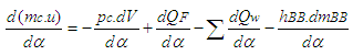 | (1) |
where = change of the internal energy in the cylinder.
 = piston work.
 = fuel heat input.
 = wall heat losses
 = enthalpy flow due to blow-by
 = blow-by mass flowThe first law of thermodynamics for high pressure cycle states that the change of internal energy in the cylinder is equal to the sum of piston work, fuel heat input, wall heat losses and the enthalpy flow due to blow-by. In order to solve this equation, models for the combustion process and the wall heat transfer, as well as the gas properties as a function of pressure, temperature, and gas composition are required together with the gas equation
 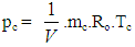 | (2) |
Establishing the relation between pressure, temperature and density, Eq. 2 for in-cylinder temperature can be solved using a Runge-Kutta method. Once the cylinder gas temperature is known, the cylinder gas pressure can be obtained from the gas equation.
3.2. Combustion Model
Heat Release Approach - Vibe Two ZoneThe rate of heat release and mass fraction burned is specified by the Vibe function given by equation (3) below. The first law of thermodynamics is applied separately to the burned and unburned mixture while assuming that the temperatures of these two mixtures is different.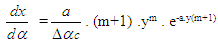 | (3) |
 | (4) |
 | (5) |
The integral of the vibe function gives the fraction of the fuel mass which was burned since the start of combustion: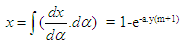 | (6) |
3.3. Gas Exchange Process Basic Equation
The equation for the simulation of the gas exchange process is also the first law of thermodynamics: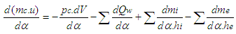 | (7) |
The variation of the mass in the cylinder can be calculated from the sum of the in-flowing and out-flowing masses: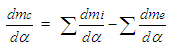 | (8) |
3.4. Piston Motion
Piston motion applies to both the high pressure cycle and the gas exchange process.For a standard crank train the piston motion as a function of the crank angle α can be written as: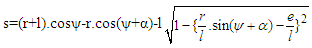 | (9) |
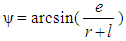 | (10) |
3.5. Heat Transfer
The heat transfer to the walls of the combustion chamber, i.e. the cylinder head, the piston, and the cylinder liner, is calculated from: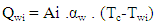 | (11) |
In the case of the liner wall temperature, the axial temperature variation between the piston TDC and BDC position is taken into account: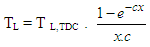 | (12) |
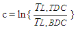 | (13) |
For the calculation of the heat transfer coefficient, the Woschni 1978 heat transfer model is used.
3.6. Woschni Model
The woschni model published in 1978 for the high pressure cycle is summarized as follows: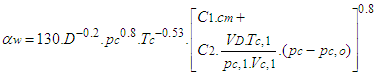 | (14) |
C1 = 2.28+0.308.cu/cmC2 = 0.00324 for DI enginesFor the gas exchange process, the heat transfer coefficient is given by following equation: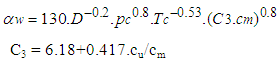 | (15) |
3.7. Fuel Injector
The fuel injector model is based on the calculation algorithm of the flow restriction. This means that the air flow rate in the fuel injector depends on the pressure difference across the injector and is calculated using the specified flow coefficients. For the injector model, a measuring point must be specified at the location of the air flow meter. In this case the mean air flow at the air flow meter location during the last complete cycle is used to determine the amount of fuel. As is the case for continuous fuel injection, the fuelling rate is constant over crank angle.
3.8. Pipe Flow
The one dimensional gas dynamics in a pipe are described by the continuity equation 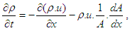 | (16) |
the equation for the conservation of momentum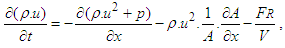 | (17) |
and by the energy equation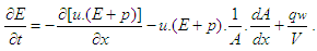 | (18) |
The wall friction force can be determined from the wall friction factor  :
: | (19) |
Using the Reynold’s analogy, the wall heat flow in the pipe can be calculated from the friction force and the difference between wall temperature and gas temperature: | (20) |
During the course of numerical integration of the conservation laws defined in the Eq.18, Eq.19 and Eq.20, special attention should be focused on the control of the time step. In order to achieve a stable solution, the CFL criterion (stability criterion defined by Courant, Friedrichs and Lewy) must be met: | (21) |
This means that a certain relation between the time step and the lengths of the cells must be met. The time step to cell size relation is determined at the beginning of the calculation on the basis of the specified initial conditions in the pipes. However, the CFL criterion is checked every time step during the calculation. If the criterion is not met because of significantly changed flow conditions in the pipes, the time step is reduced automatically.An ENO scheme is used for the solution of the set of non-linear differential equations discussed above. The ENO scheme is based on a finite volume approach. This means that the solution at the end of the time step is obtained from the value at the beginning of the time step and from the fluxes over the cell borders.
3.9. Knock Model
Ignition Delay and Octane Number RequirementAVL Boost uses the following equation based model proposed by Hires etal. for the calculation of ignition delay in combustion.  where
where 
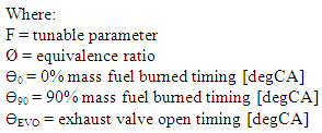
 = ignition delayON = Octane Number RequirementA = 17.68 msB = 3800 Ka = 3.402n = 1.7
3.10. Mechanism of CO Emissions Formation
CO formation is one of the principal reaction steps in the hydrocarbon combustion, which may be summarized byRH → R → RO2 → RCHO → RCO → COWhere R stands for the hydrocarbon radical.The forward rate constant for this reaction is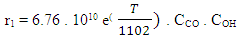 The backward reverse reaction rate constant for CO formation is
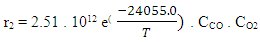 The final rate of CO production /destruction in [mole/cm3s] is calculated as:
 with
with 
3.11. Mechanism of NOx Emissions Formation
The NOx formation model implemented in BOOST is based on Pattas and Hafner. The following 6 reactions (based on the well known Zeldovich mechanism are taken into account.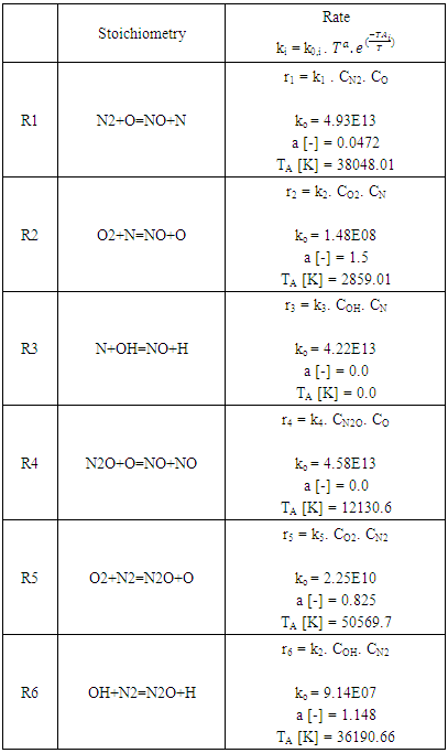 All reaction rates ri have the units [mole/cm3s] the concentrations ci are molar concentrations under equilibrium conditions with units [mole/cm3]. The concentration of N2O is calculated according to:
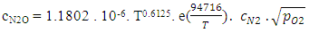 The final rate of NO production /destruction in [mole/cm3] is calculated as:
 with
with 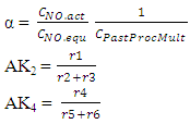
3.12. Mechanism of HC Emissions Formation
The following three mechanisms of unburned hydrocarbons emissions can be identified in spark ignition engines:1) Crevice MechanismThe mass of unburned charge in the crevices between the piston rings and the cylinder at any time is equal to: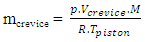 where:mcrevice = mass of unburned charge in the crevicesp = cylinder pressureVcrevice = total crevice volumeM = unburned molecular weightR = gas constantTpiston = piston temperature2) HC absorption/desorption mechanismThe hydrocarbons from the fuel are initially absorbed by the lubricating oil during the compression process because of diffusion process and then later desorbed at the end of combustion process during the exhaust period.The radial distribution of the fuel mass fraction in the oil film can be determined by solving the diffusion equation:
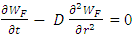 Where:WF = mass fraction of the fuel in the oil film.t = timer = radial position in the oil filmD = relative (fuel-oil) diffusion coefficientThe diffusion coefficient can be computed applying the following relation:
 Where M = oil molecular weightT = oil temperaturevf = molar volume of the fuel at normal boiling conditionsµ = oil viscosity3) Partial burn effectsQuench layer and partial burn effects can be modeled by the semi-empirical correlation given below.
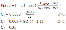
4. Results and Discussions
4.1. Effect of Speed on Octane Number Requirement
The Fig.1 below shows the effect of speed on the octane demand of the engine. The computational investigations were done in order to set the maximum octane demand of the engine at 95. This corresponds to the assumption that the commercial petrol or gasoline has an octane number of 95. It is clear that the octane demand of the engine corresponding to the design and operating conditions given in the Table 1 below for the cases of maximum power output and minimum CO emissions is almost overlapping between the limits of 95 and 60. 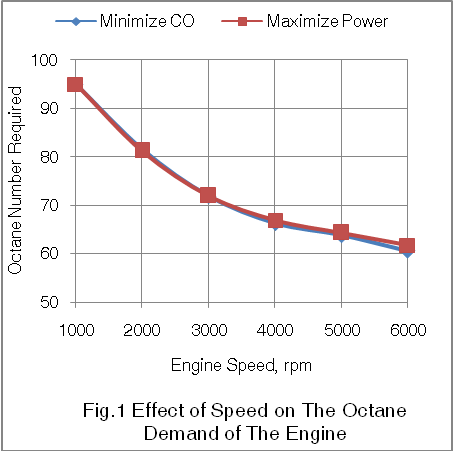 | Figure 1 |
Table 1
 |
| |
|
4.2. Effect of Speed CO Emissions
The Fig.2 below shows the effect of speed on CO emissions produced by the engine for the alternative cases of engine design for maximum power and minimum CO emissions.It is seen from the figure that in general the CO emissions per unit of energy output produced by the engine increase with the increase in speed. This is due to more number of power cycles per unit time executed by the engine at higher speeds.As per the model used for the mechanism of CO formation it is seen that the forward reaction rate constant increases with increase in the temperature of gas in the engine cylinder. Further it is seen that the temperature of the exhaust gas is higher in the engine designed for maximum power generation than the engine designed for minimize CO emissions. By substituting the values of these temperatures in the model adopted for the mechanism of CO formation in the engine the computed CO emissions are lower for the engine designed for minimum CO emissions than the engine designed for maximum power.The design modifications done by reducing the compression ratio from 9.25 to 8.4 and retarding the start of combustion or the spark timing from 715 DCA to 710 DCA resulted in the drop in the temperature of the exhaust gas from the engine which brought down the CO emissions in the modified engine design as per the thermodynamic model used.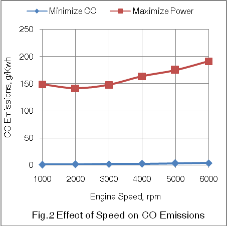 | Figure 2 |
Table 2
 |
| |
|
4.3. Effect of Speed on Engine Power
The Fig.3 below shows the effect of speed on the power developed by the engine for the cases of alternative engine design for maximum power and minimum CO emissions.It is seen from the figure that power produced by the engine designed for the case of minimum CO emissions, as per the design and operating conditions chosen, has dropped down marginally. This is due to drop in fuel consumed per unit of energy output produced by the engine designed for the case of minimum CO emissions. 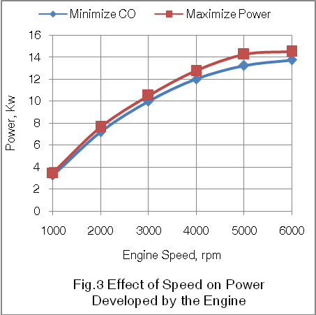 | Figure 3 |
4.4. Effect of Speed on Engine Torque
The Fig.4 below shows the effect of speed on the torque developed by the engine for the cases of engine design for maximum power and minimum CO emissions.It is seen that the torque developed by the engine designed for minimum CO emissions is reduced. This is due to the reduction in the fuel consumption per unit of energy output produced by the engine when designed for minimum CO emissions. 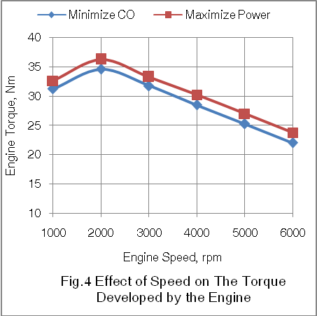 | Figure 4 |
4.5. Effect of Speed on Brake Specific Fuel Consumption
The Fig.5 below shows the effect of speed on the fuel consumed by the engine per unit of energy output produced by the engine for the two alternative designs for maximum power and minimum CO emissions.It is clear from the graph that the fuel consumed by the engine per unit of energy output produced by the engine is lesser for the case of engine design for minimum CO emissions.The drop in brake specific fuel consumption is due to the fact that while simulating to maintain the maximum octane demand of the engine below 95 and also to reduce the CO emissions as much as possible, the compression ratio was reduced from 9.25 to 8.4 by simulation process. Further the thermodynamic simulations retarded the spark timing from 715DCA to 710DCA to achieve the objective behind the alternative designs.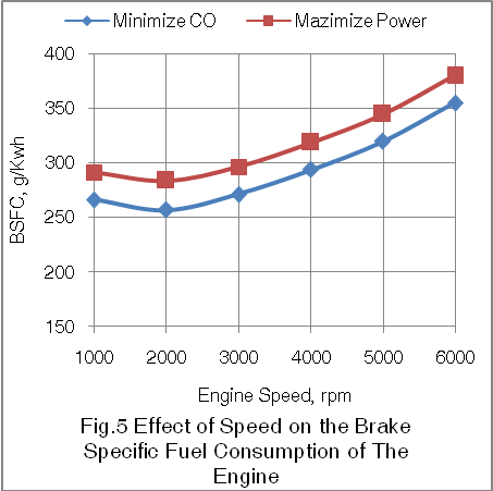 | Figure 5 |
4.6. Effect of Speed on HC Emissions
The Fig.6 below shows the effect of speed on the hydrocarbon emissions produced by the engine.It is seen from the figure that the engine designed for the case of minimum CO emissions also produces lesser HC emissions. This is due to a reduction in the brake specific fuel consumption of the engine when designed for possible minimum CO emissions. Further as per the mechanism used for crevice based HC pollutants, the higher cylinder pressures for the case of maximum power will increase this fraction of HC emission. Also the mechanism used for the absorption and desorption based HC emissions, it is seen that for the case of maximum power generation, higher gas temperatures will increase the temperature of the engine components thus decreasing the viscosity of the engine oil. This in turn increase the magnitude of absorption and desorption of HC in the engine oil. Thus during maximum power generation case the HC emission component from the engine oil will increase. Further as per the quench layer and partial burn mechanism for HC emissions formation, this type of HC emissions are on higher side under cold engine conditions corresponding to low speeds and warm up.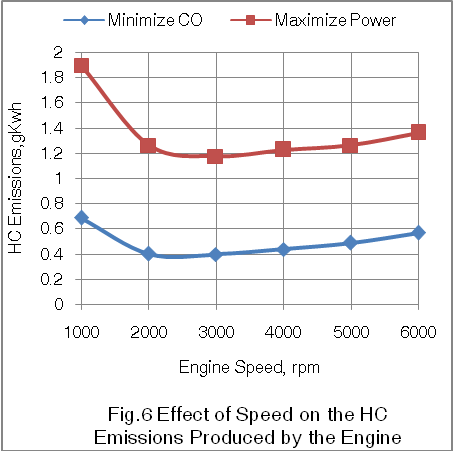 | Figure 6 |
4.7. Effect of Speed on NOx Emissions
The Fig.7 below shows the effect of speed on the NOx emissions produced by the engine for the two possible cases of engine design for maximum power and minimum CO emissions.It is clear from the figure that the engine designed for possible minimum CO emissions case produces more NOx emissions as compared to the engine designed for maximum power generation. 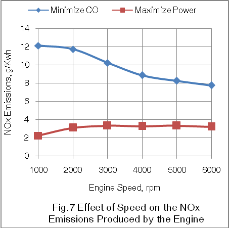 | Figure 7 |
This is due to the fact that both the types of engines were designed for stoichiometric or chemically correct combustion cases. Again while maintaining the same displacement volume for both the cases, the reduction in the fuel consumption for the case of minimum CO emissions results in more amount of air being available for possible conversion into nitric oxides.
4.8. Effect of Speed on Exhaust Gas Temperature
The Fig.8 below shows the effect of speed on the exhaust gas temperature produced by the engine for its possible design for the alternative cases of maximum power and minimum CO emissions. It is seen from the figure that the engine designed for maximum power produces higher exhaust gas temperatures as compared to the engine designed for minimum CO emissions. This is due to higher fuel consumption under maximum power generation condition. 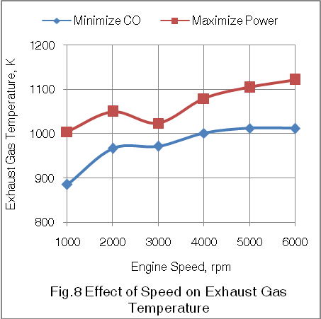 | Figure 8 |
5. Conclusions
1. Since the octane number of the commercial gasoline is 95, the octane demand of a gasoline based spark ignition engines remains a decisive factor while designing this engine with alternative objective functions of power boosting or CO emissions reduction. This ensures normal combustion based engine performance. 2. The engine design optimized for minimum CO emissions brings a drastic reduction in the CO emissions produced by this engine in the range of 99.55% at the idle speed of 1000rpm to 98.0% at the rated speed of 6000rpm as compared to the engine designed for maximum power generation.3. The engine design optimized for minimum CO emissions produces lower HC emissions in the range of 69.07% at the idle speed of 1000rpm to 58.26% at the rated speed of 6000rpm as compared to the engine designed to produce maximum power.4. However the power developed by the engine designed for minimum CO emissions is lower in the range of 7.14% at the idle speed of 1000rpm to 5.17% at the rated speed of 6000rpm as compared to the engine design optimized to maximize the power output of the engine.5. Also the torque developed by the engine designed for minimum CO emissions is lower in the range of 4.14% at the idle speed of 1000rpm to 7.36% at the rated speed of 6000rpm as compared to the engine designed for maximum power generation.6. Further the engine designed for minimum CO emissions consumes lesser fuel per unit of energy output produced by the engine in the range of 8.58% at the idle speed of 1000rpm to 6.57% at the rated speed of 6000rpm as compared to the engine designed for maximum power generation.7. However the NOx emissions are lower with the engine design meant for maximum power generation in the range of 81.64% at the idle speed of 1000rpm to 58.5% at the rated speed of 6000rpm as compared to the engine design optimized for minimum CO emissions.8. The methodology for designing a 95 octane gasoline based spark ignition engine alternatively for maximum power and minimum CO emissions can be extended to the design of same type of engine for any other suitable S.I engine fuel like 108 octane ethanol and 120 octane CNG.
ACKNOWLEDGEMENTS
Author is thankful to AVL Austria and its unit AVL India Ltd for providing BOOST thermodynamic engine simulation software with free license for academic research purposes.
Nomenclature
a = speed of soundA = pipe cross-sectionAeff = effective flow areaAi = surface area (cylinder head, piston, liner)AFCP = air fuel ratio of combustion productsAgeo = geometrical flow areac = mass fraction of carbon in the fuelcV = specific heat at constant volumecp = specific heat at constant pressureC1 = 2.28+0.308.cu/cmC2 = 0.00324 for DI enginesCm = mean piston speedCu = circumferential velocitycu = circumferential velocityD = cylinder boreD = pipe diameterdmi = mass element flowing into the cylinderdme = mass element flowing out of the cylinderdvi = inner valve seat diameter (reference diameter) = blow-by mass flowe = piston pin offsetE = energy content of the gas
  f = fraction of evaporation heat from the cylinder chargeFR = wall friction forceh = mass fraction of hydrogen in the fuelhBB = enthalpy of blow-byhi = enthalpy of in-flowing masshe = enthalpy of the mass leaving the cylinderHu = lower heating valuek = ratio of specific heatsl = con-rod lengthm = shape factor
 = mass flow ratemc = mass in the cylinder mev = evaporating fuelmpl = mass in the plenumn = mass fraction of nitrogen in the fuelo = mass fraction of oxygen in the fuelp = static pressureP01 = upstream stagnation pressurePc,o = cylinder pressure of the motored engine[bar]Pc,1 = pressure in the cylinder at IVC[bar]ppl = pressure in the plenumpc = cylinder pressurep2 = downstream static pressureqev = evaporation heat of the fuelqw = wall heat flowQ = total fuel heat inputQF = fuel energyQwi = wall heat flow (cylinder head, piston, liner)r = crank radiusR0 = gas constants = piston distance from TDCt = time T = temperatureTc,1 = temperature in the cylinder at intake valve closing (IVC)Tc = gas temperature in the cylinderTwi = wall temperature (cylinder head, piston, liner)TL = liner temperatureTL,TDC = liner temperature at TDC positionTL,BDC = liner temperature at BDC positionTw = pipe wall temperatureT01= upstream stagnation temperatureu = specific internal energyu = flow velocityV = cylinder volumeV = cell volume (A.dx)VD = displacement per cylinderw = mass fraction of water in the fuelx = relative stroke (actual piston position related to full stroke)x = coordinate along the pipe axisα = crank angleαo = start of combustionΔαc = combustion durationαw = heat transfer coefficientρ = densityμσ = flow coefficient of the portψ = crank angle between vertical crank position and piston TDC position
 = wall friction coefficientΔt = time stepΔx = cell length
References
| [1] | Heywood John B., “Fundamentals of Internal Combustion Engines”, A McGraw Hill International Publication, 1991. |
| [2] | Crawford, A., Ellis, G., Fraser, N., Steeples, B. et al., “Combining High Performance with Euro IV Capability in a Naturally Aspirated Production Engine”, SAE Technical Paper No 2002-01-0335, 2002. |
| [3] | Ikeya, K., Takazawa, M., Yamada, T., Park, S., et al., “Thermal Efficiency Enhancement of a Gasoline Engine”, SAE International Journal of Engines, Paper No 2015-01-1263, 2015. |
| [4] | Reinhart, T. and Megel, M., “An Efficient, Durable Vocational Truck Gasoline Engine”, SAE Int. Journal of Engines, Paper No 2016-01-0660, 2016. |
| [5] | Lee, B., Oh, H., Han, S. et al., “Development of High Efficiency Gasoline Engine With Thermal Efficiency over 42%”, SAE Technical Paper No 2017-01-2229, 2017. |
| [6] | Taylor C., Taylor E., and Williams G., “Fuel Injection with Spark Ignition In An Otto-Cycle Engine”, SAE Technical Paper 310005, 1931. |
| [7] | Herbsleb K., Loenzen L., and Kofoed E., “Lean Combustion In A High Compression Four Stroke Gasoline Engine”, SAE Technical Paper 810786, 1981. |
| [8] | Nakamura N., Baika T., and Shibata Y., “Multipoint Spark Ignition For Lean Combustion”, SAE Technical Paper 852092, 1985. |
| [9] | De Petris C., Diana S., Giglio V., and Police G., “High Efficiency Stoichiometric Spark Ignition Engines”, SAE Technical Paper 941993, 1994. |
| [10] | Stovell C., Matthews R., Johnson B., Ng. H., et.al., “Emissions and Fuel Economy of a 1998 Toyota With a Direct Injection Spark Ignition Engine”, SAE Technical Paper 1991-01-1527, 1999. |
| [11] | Al-Muhsen, N. and Hong., “Effect of Spark Timing on Performance and Emissions of a Small Spark Ignition Engine with Dual Ethanol Fuel Injection”, SAE Technical Paper 2017-01-2230, 2017. |
| [12] | AVL LIST Gmbh, AVL BOOST Theory, Version 2009.1. |

 Abstract
 Reference
 Full-Text PDF
 Full-text HTML