-
Paper Information
- Previous Paper
- Paper Submission
-
Journal Information
- About This Journal
- Editorial Board
- Current Issue
- Archive
- Author Guidelines
- Contact Us
Energy and Power
p-ISSN: 2163-159X e-ISSN: 2163-1603
2018; 8(2): 56-60
doi:10.5923/j.ep.20180802.04

Single Arm, Centrifugal, Water Turbine for Low Head and Low Flow Application: Part 2- Performance Evaluation
 Abstract
 Reference
 Full-Text PDF
 Full-text HTML
Kiplangat C. Kononden1, Augustine B. Makokha1, Sitters W. M. Cox2
1Department of Energy Engineering, Moi University, Eldoret, Kenya
2Department of Civil & Structural Engineering, Moi University, Eldoret, Kenya
Correspondence to: Augustine B. Makokha, Department of Energy Engineering, Moi University, Eldoret, Kenya.
| Email: |  |
Copyright © 2018 The Author(s). Published by Scientific & Academic Publishing.
This work is licensed under the Creative Commons Attribution International License (CC BY).
http://creativecommons.org/licenses/by/4.0/

This paper presents performance analysis of the single arm centrifugal reaction water turbine described in Part 1 of our research. Experimental tests were conducted to assess the power output and efficiency of the turbine by varying the head, orifice diameter and the arm radius. The results obtained show that; the radial arm length affects the operating angular velocity, output torque as well as the overall turbine efficiency. The turbine exhibited maximum efficiency of 83% and 40% at heads of 1.85m and 11.5m respectively. The corresponding ratio of cross-sectional area of nozzle to main conduit was in the range of 0.18 to 0.24. It is concluded that the semi-circular centrifugal reaction water turbine is a fairly suitable type of turbine for low head and low-medium flow application. Based on the results obtained, an arm conduit with a larger cross-sectional area would be recommendable to achieve higher discharge. But further research is still needed on how best the water from the reservoir would get into the turbine and exit.
Keywords: Turbine, Low head, Low flow, Centrifugal, Micro-hydro
Cite this paper: Kiplangat C. Kononden, Augustine B. Makokha, Sitters W. M. Cox, Single Arm, Centrifugal, Water Turbine for Low Head and Low Flow Application: Part 2- Performance Evaluation, Energy and Power, Vol. 8 No. 2, 2018, pp. 56-60. doi: 10.5923/j.ep.20180802.04.
Article Outline
1. Introduction
- Hydropower is a very good example of renewable energy and it is the most reliable base-load energy source. Nevertheless, there is a huge untapped exploitable hydro energy potential
 [1, 2] mainly from Micro-hydropower sources waiting to be utilized throughout the world.There are few small to medium scale low head and low volume flow rate hydro turbines commercially available, but they are very expensive and inefficient for micro power generation at individual level. Therefore, there is an inherent need of a simple, efficient and low cost hydro turbine that can enhance the exploitation of hydropower available in small rivers and streams where the head and flow rate are typically low.Past research on simple reaction turbine [3, 4] show that fluid frictional losses are mainly dependent on the exit velocity (relative velocity) of the water leaving the turbine. In his research Date [4] managed to build a simple reaction turbine prototype that performed with a maximum efficiency of 66.7% while operating with a head of 4.5 and a flow rate of 21L/sec (0.021m3/sec). However the effect of turbine structure on the turbine’s performance as well as effect of the operating head is still not well understood [6]. Moreover, the current knowledge on the effect of orifice variation on the turbine performance is not sufficient for absolute conclusions. This work extends on other experiments in the field of simple reaction turbines with the aim of carrying out a comprehensive performance analysis of the single arm centrifugal reaction water turbine. This would yield more information on nozzle size variation, head variation as well radial arm length variation and their optimums in relation to turbine performance.
 2. Experimental Work
2.1. Methodology
- The model turbine utilised in this study was fabricated at the University’s Engineering workshop using the locally available materials. Design details of the turbine can be reviewed in Part 1 of our work. The design parameters that were varied included; nozzle size, radial arm length and the supply head. The ratio of cross-sectional area of main pipe to nozzle is another key design parameter that was assessed to establish the optimum ratio. A set of nozzle sizes were randomly selected starting from the highest to the smallest while maintaining an even distribution of the same. The ratios investigated were ≤ 1. A ratio of one represent a case where no nozzle is used (i.e. orifice diameter is equal to the main conduit internal diameter), while a ratio of zero represent a case where the turbine conduit has no exit (i.e. flow is zero). The internal diameter of the main radial conduit was 11.5mm, while the nozzle diameters were; 8.8mm, 6.0mm, 3.8mm, 2.5mm. In order to get the nozzle to main pipe cross-sectional area ratio, the cross-sectional area of the orifice of the nozzle is divided by cross-sectional area of the main pipe and is denoted as (1/n). For the nozzle diameters selected here, the ratio (1/n) equals; 1, 0.5856, 0.2722, 0.1092, 0.0473, 0 arranged from the highest to the lowest. The arm radius was varied in three steps of R = 0.25m, 0.5m, 1.0m. By varying the radial arm length and keeping other variables constant and measuring the variations in the angular speed, torque and flow rate, the effects of the radial arm length on the output power were studied.To study the effect of head variation the experiments were performed under two different heads of H = 1.85m and 11.5m. For each experiment the efficiency of the turbine was calculated. The lower head of H=1.85m was set by connecting the delivery pipe to the raised tank. Conversely the high head of H=11.5m was achieved by directly connecting the supply pipe to the high pressure tap source at the Laboratory.
2.2. Experimental Setup
- Figure 1 shows a snap shot of the setup of the turbine test rig used in the current study. The test rig consists of the following components;
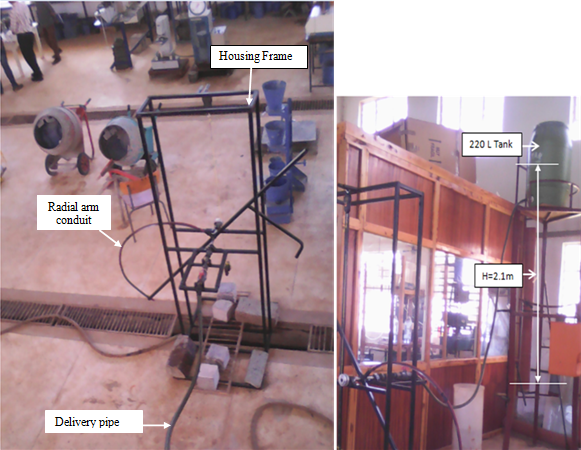 | Figure 1. Picture of the turbine set up |
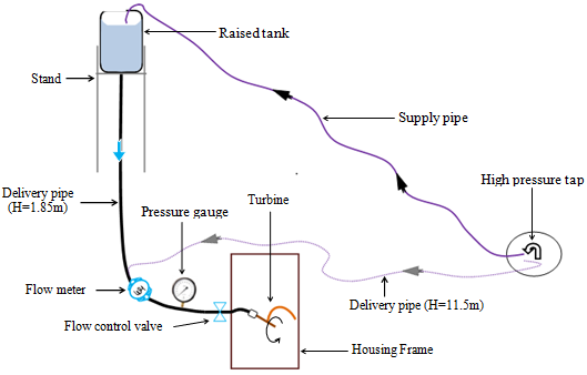 | Figure 2. Schematic diagram of the test rig |
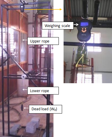 | Figure 3. Rope Brake dynamometer with a digital weighing machine |
2.3. Test Procedure
- In all the experimental tests conducted both the input and output power tests are done simultaneously. At the start of the tests, the turbine is allowed to rotate freely without any load, while the operating head is kept constant. Using the relevant instruments, the parameters such as flow rate, rotational speed and operating torque were measured simultaneously and recorded. A dead load was placed on the lower rope of the rope brake dynamometer as shown in figure 3 and is gradually increased in steps, leading to a decrease in the rotational speed of the turbine. The decrease in rotational speed tends to penalize the centrifugal pumping effect causing a reduction in the water flow rate. Note that, the flow rate, rotational speed, and operating torque are recorded each time the load is increased. The increase in load is maintained till the turbine slows down to a stop. The experiment is repeated for each radial arm length and for the five nozzle sizes. This procedure is replicated for the higher operating head of 11.5m. This was done for purposes of comparing the performance characteristics of the turbine under low hydrostatic head (H=1.85m) and under high hydrostatic head (H=11.5m). All the generated data were recorded manually on data charts. The obtained data was analysed using Microsoft Excel.
3. Results and Discussion
3.1. Turbine Efficiency
- From theoretical analysis, turbine efficiency is given by the following relation;
 | (1) |
 is the theoretical output power while
  is the available power. They are obtained from the following relations:
 | (2) |
 | (3) |
 is the actual operating height after subtracting all the head losses. The other parameters retain their previous definitions. Using equation (2) and (3), the theoretical output power
  is obtained as
  while the available power
  is obtained as
  . This gives theoretical efficiency of 93.4%. The values of parameters used in the calculations are as follows:
  and
and  . The value of
  is obtained using the relation,
 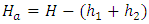 in which
  and
and  are the average head losses due to frictional resistance in the delivery pipe and the turbine’s semicircular pipe, computed using Darcy-Weisbach equation [8].
3.2. Nozzle Size and Arm Length
- The trends in turbine efficiency for different values of nozzle to main pipe cross-sectional area ratio (1/n) and arm length (R) were studied to find the optimum levels. The highest efficiencies for each of the five nozzles used in the low head and high head experiments were compared. The procedure was replicated for each of the three arm lengths.
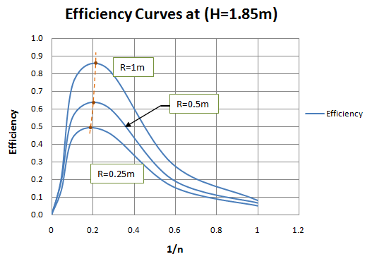 | Figure 4. Efficiency against (1/n) for different arm radii when H=1.85m |
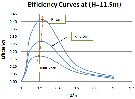 | Figure 5. Efficiency against (1/n) for different arm radii at H=11.5m |
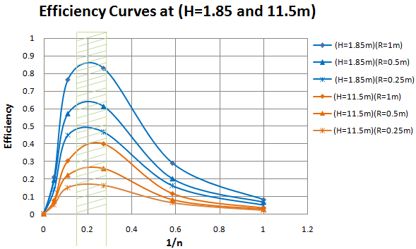 | Figure 6. Efficiency against (1/n) for low and high head |
 | (4) |
 | (5) |
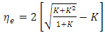
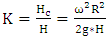
3.3. Optimum Values of Parameter ‘K’ and Factor ‘k’
- Using the calculated theoretical efficiency
 , as well as the actual experimental efficiency
  , the values of parameters ‘K’ and ‘k’ can be obtained. From the theoretical analysis of the turbine the expression of theoretical efficiency is given by equation (6);
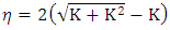 | (6) |
4. Conclusions
- The main objective of this study was to assess the performance of a model scale single arm centrifugal water turbine in terms of efficiency and power. The primary design parameters were nozzle size and arm length while operational parameters were flow rate, available head and rotational speed. The results show that, the turbine efficiency increases with increase in arm radius for the range tested here. The maximum turbine efficiency obtained at low head (H=1.85m) was 83%, and at high head (H=11.5m) was 40.11%. This implies that a lot of potential energy is wasted when operating at relatively higher heights for this type of turbine. Further, the results reveal that an optimum operating nozzle to main conduit cross-sectional area ratio lies between 0.18 and 0.24. These results reinforce findings by other researchers that a single arm centrifugal reaction water turbine is economical for low head and low flow conditions. Nonetheless, further research is needed to establish the most suitable inlet and discharge mechanism for the turbine.
ACKNOWLEDGEMENTS
- The authors wish to thank the Centre of Excellence in Phytochemistry, Textiles and Renewable Energy (ACE II) at Moi University for sponsoring this research and the technical staff of mechanical engineering workshop for their help during the fabrication of the turbine prototypes and test rig modification.