Kiplangat C. Kononden1, Augustine B. Makokha1, Sitters W. M. Cox2
1Department of Energy Engineering, Moi University, Eldoret, Kenya
2Department of Civil & Structural Engineering, Moi University, Eldoret, Kenya
Correspondence to: Augustine B. Makokha, Department of Energy Engineering, Moi University, Eldoret, Kenya.
| Email: |  |
Copyright © 2018 The Author(s). Published by Scientific & Academic Publishing.
This work is licensed under the Creative Commons Attribution International License (CC BY).
http://creativecommons.org/licenses/by/4.0/

Abstract
Many parts of sub-Saharan Africa have small streams and rivers that have a potential to produce hydropower on small scale for rural and off-grid applications. However, the high cost of commercially designed micro-hydro turbines limits the exploitation of the available hydropower. Thus any efforts to improve the understanding of the fundamental principles involved in the design, manufacture, and operation of simple micro-hydro turbines that could be constructed from readily available low cost materials and construction methods would be invaluable. This paper presents the fundamental theory and the methodology for design of a single arm centrifugal reaction water turbine that would allow efficient extraction of hydro-power. Continuum mechanics approach was adopted where the design of the turbine was derived from a mathematical model that was based on the balance equations formulated in a rotating control volume. The model showed that the theoretical power output is equivalent to the product of the following: density of water, volume flow rate, angular velocity of the turbine, radial length of the turbine arm and the absolute velocity of water as they exit the turbine. Further, the analysis showed that the theoretical efficiency of the turbine is directly proportional to the ratio of angular acceleration to the gravitational acceleration. The experimental test results of the model turbine are presented in our subsequent work (Part 2).
Keywords:
Turbine, Low head, Low flow, Centrifugal, Micro-hydro
Cite this paper: Kiplangat C. Kononden, Augustine B. Makokha, Sitters W. M. Cox, Single Arm, Centrifugal, Water Turbine for Low Head and Low Flow Application: Part 1- Theory and Design, Energy and Power, Vol. 8 No. 2, 2018, pp. 51-55. doi: 10.5923/j.ep.20180802.03.
1. Introduction
Hydro energy contributes the highest percentage towards electricity generation in the renewable realm and is evenly distributed across the world [1]. For the last one and half centuries hydroelectric production comes mostly from large projects, with dams that require a large reservoir of water to supply the turbine generator. Since most of the best locations for this type of hydro power around the world and even in Africa are already being used, research and development for hydro power is moving towards micro-hydro systems, which require less water to operate and can supply electricity to smaller communities or individual homes.This means that there is need for the most efficient and reliable machines for this application. Turbines are more often than not, used for the transformation of hydro energy to mechanical energy. Most historians consider turbines as the prime haulers of civilization for the last four centuries. Even so currently there are a few companies who manufacture turbines and supply equipment for generation of electricity from micro hydro sources. Most of the low head micro hydroelectric units available use impulse type turbines for energy conversion [2]. From the turbines literature review, it is clear that impulse turbines are suitable for high head and low volume flow rate applications only. When impulse turbines are used for low head operation their energy conversion efficiency drops drastically to even less than 60% [3, 4].Furthermore the current turbines are complex to manufacture, more so in the ordinary workshops since most of them require moulding processes and dedicated machines to fabricate [5]. This alone, contributes a lot to their extremely high cost. To curb this barrier the turbine designed in this paper emphasises on low-cost fabrication which means the use of locally available material.Some of the previous turbines that have attempted to solve the structural impediment in micro-power generation include the following: Hero’s turbine, Barker’s mill, Ján Andrej Segner turbine, Pupil’s turbine, Whitlaw’s turbine and cross-flow turbine. The latest simple reaction water turbine is the split reaction turbine by Abhijit Date [6]. As much as subsequent years have seen modifications to increase the efficiency of the Barker’s mill turbine design, some scientist regard it as obsolete and not economically viable to be used any more [7]. However some writers like Akbarzadeh et al [8] seem to dispute such views. Their analysis showed that to large extent the simple reaction water turbine is misunderstood. In their paper Akbarzadeh et al [op cit] have identified the main geometric and operational parameters. They concluded that the energy conversion efficiency of a simple reaction water turbine increases with the increase in the rotational speed among other factors.Despite recent researches on the simple reaction turbine there is still some gap on the effects of head variation to the performance of the simple reaction turbine. Also the effect of using a single nozzle outlet or a single arm structure on the performance has not been well articulated. This paper aims at presenting a continuum analysis on the consequence of the head variation as well as the variation of radial arm length on the performance of a simple reaction turbine in relation to its design. Moreover the corollary of nozzle losses on the turbine performance has been presented here. The analysis of these key factors will help solve some of the impediments faced when using a simple reaction turbine for micro hydro generation.
2. Conceptual Design of the Turbine
Figure 1 shows the graphical design concept of the single arm centrifugal reaction water turbine. The intake stationary pipe is connected on one side to the penstock via a flow control valve and on the other side is joined to the intake rotary pipe using a special mechanical rotary seal joint device. Bearings are mounted onto the central output shaft such that the arm is at the middle and the intake rotary pipe on one end.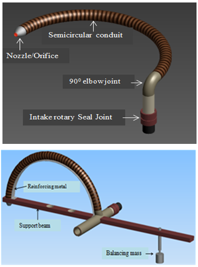 | Figure 1. Graphical representation of the single arm centrifugal reaction turbine design |
3. Continuum Analysis of the Turbine
3.1. Continuum Theory
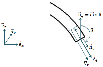
Most of the past researches on the simple reaction water turbine use a rather ad-hoc analysis to give a mathematical model of the turbine [6, 8, 10]. In this paper, the analysis presented, uses a continuum mechanics approach to derive a mathematical model of a single arm reaction water turbine. The balance equations for continuity, moment of momentum and energy have to be evaluated to derive the relations for the generated torque, speed and efficiency of the turbine as a function of rotational speed and other input parameters such as rate of flow and supplied water head. These equations have to be derived for the moving turbine arm, which necessitates the use of a transport theorem for a moving control volume.Figure 2 shows the configuration of a rotating one arm reaction turbine. At the pivoting centre water is flowing into the turbine and at the exit nozzle the water leaves the turbine. The control volume coincides with the circular tube at the entry and exit areas and thus rotates with the same speed as the turbine. 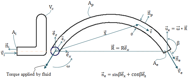 | Figure 2. Flow in a one arm reaction turbine control volume |
The various notations are explained:Ÿ Symbol  is used to indicate the absolute flow velocity with respect to fixed coordinate system
  .
.  represents the absolute flow velocity of water flowing into the “moving control volume” via the inlet pipe. While
  represents the absolute flow velocity of water exiting the moving control volume via the nozzle.Ÿ
  is an outwardly directed unit normal to the inlet cross-sectional area. While
  is an outwardly directed unit normal to the surface of the semi-circular conduit. Furthermore
  is an outwardly directed unit normal to the outlet cross-sectional area.Ÿ The cross-sectional area at the inlet of the one arm reaction turbine is represented by
  . Conversely
  represents the surface area along the semicircular conduit. While
  represents the outlet cross-sectional area at the end of the semi-circular conduit. Ÿ
  denotes the volume occupied by water within semicircular conduit of the one arm reaction turbine, also referred as a moving control volume. While capital V is used to represent volume in general.Ÿ
  is the distance of a fluid particle from the centre of rotation to a certain position in the control volume.Ÿ
  is the distance of nozzle from the centre of rotation.Ÿ
  is the linear velocity at the end of the turbine arm as the turbine rotate and is given by
  .Ÿ Angle
  is the angle between the vectors
  and
and  , usually referred as the angle of jet projection.Ÿ The internal diameter of the semicircular conduit is denoted by
  .The velocity of the control volume
  is equal to:
  . The angular velocity vector and the radial vector are given by:
 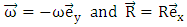 .Therefore;
 The next step in the analysis is to formulate the balance equations for the moving control volume, in order to obtain the algebraic equations governing the problem.
3.2. Mass Conservation
Using continuum mechanics approach for a moving control volume, the continuity equation for a one arm reaction turbine becomes: 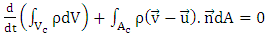 | (1) |
Figure 3 shows the velocity diagram at the nozzle for  and
and  .
. | Figure 3. Velocity diagram of the nozzle |
Assuming velocities are constant over cross-section, the continuity equation becomes: | (2) |
Using  the continuity equation finally results into:
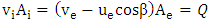 | (3) |
3.3. Moment of Momentum (Angular Momentum)
The moment of momentum equation for a one arm reaction turbine is given by: | (4) |
Again the first term is equal to zero, since the integral is constant. Furthermore the effect of gravity within the turbine balances to approximately zero and can be neglected. Therefore: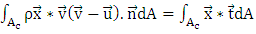 | (5) |
Solving the left hand side and applying the relevant limits, with  it is finally found:
 | (6) |
Again solving the right hand side of the equation and simplifying becomes: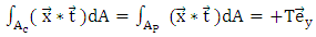 | (7) |
The integral over  is equal to the torque applied on the fluid and is denoted by
  where
where  . Consequently, the torque applied by the fluid on the arm is equal to
  .Equating the left-hand side and right-hand side of the moment of momentum equation, delivers:
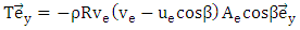 | (8) |
With  , and using the continuity equation (3) the following expressions for the moment of momentum equation can be rewritten as:
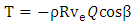 | (9) |
3.4. Energy Conservation
 | (10) |
Solving the left and right hand side of the equation and equating the two sides and further simplifying, the energy equation becomes;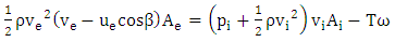 | (11) |
3.5. Bernoulli Equation for Supply Pipe
In this section the Bernoulli equation for the supply pipe is derived. This equation helps in determining  and
and  . Figure 4 shows the modelling for both the penstock and the tank.Bernoulli’s equation reads:
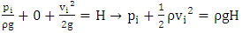 | (12) |
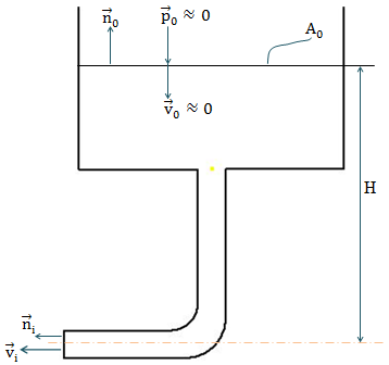 | Figure 4. Velocity diagram of the penstock and the tank |
Substituting this result into the energy equation and making use of the continuity equation and the moment of momentum equation, the following equation is arrived at;  | (13) |
Where  represents relative flow velocity.It should be noted that an “ideal” turbine is considered in the above derivations, which means that friction and other losses in the nozzle are not taken into consideration.
3.6. Calculation of Power and Efficiency without Nozzle Losses
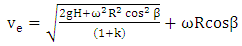
The power produced by the turbine (i.e. power performed by fluid on the tube) is calculated from the energy equation (11); | (14) |
Using the result of Bernoulli’s equation (12) and the continuity equation (3), the power equation becomes;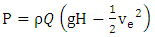 | (15) |
Introducing equation (13) and substituting it into the power equation delivers the following; | (16) |
The power available is  so that the hydraulic efficiency is given by;
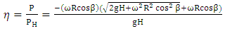 | (17) |
Introduction of head due to centrifugal pumping effect as discussed by A. Akbarzadeh [8];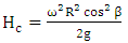 | (18) |
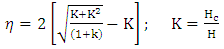
Further simplification of equation (17) and taking into account that  , the efficiency equation becomes;
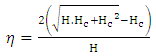 | (19) |
Or: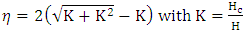 | (20) |
Figure 5 shows how efficiency varies with K, as computed from equation (20). It can be seen that as K increases the efficiency approaches one.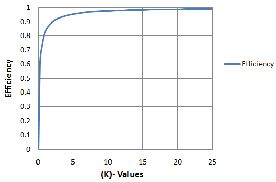 | Figure 5. Efficiency η against K |
3.7. Calculation of Power and Efficiency Factoring in Nozzle Losses
In the previous section it was assumed that an ideal fluid without friction losses was used. However, at high rotational speeds the relative velocity between nozzle and fluid becomes very high introducing energy losses which are proportional to  .To account for these losses the power equation (15) is adapted as follows:
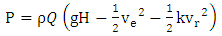 | (21) |
Where k is a proportionality factor depending on the roughness and other losses in the nozzle.The introduction of these losses will affect the exit velocity  . However, the moment of momentum equation remains unchanged. Using equation (13) and knowing that
  and with T equals to the third relation in equation (9), equation (21) transforms into:
 | (22) |
 | (23) |
Equation (23) is therefore the equation of the water jet velocity  after introduction of the frictional losses at the nozzle.
 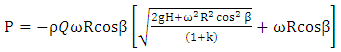 | (24) |
 | (25) |
Figure 6 shows the trend of efficiency  against K while incorporating the effect of factor k variation. The efficiency curves in figure 6 display a clear maximum. Further, it can be seen that an increase in factor k penalizes the hydraulic efficiency. In an ideal situation where there are no losses due to friction the factor k is taken to be zero. However in real life application the factor k is a value higher than zero. In our subsequent work, experiments shall be conducted to study the effects of factor k by varying the geometry and size of the nozzle.
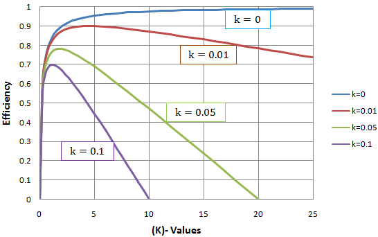 | Figure 6. Effect of factor k on turbine efficiency |
It should be clear that capital letter ‘K’ is used to denote a non-dimensional factor representing the ratio of the head due to angular acceleration to the head due to gravitational acceleration such as shown by equation (20). Conversely the small letter ‘k’ is used to denote the coefficient of friction or rather a proportionality factor depending on the roughness and other losses in the nozzle.
3.8. Determination of k
The continuity equation (equation 3) along with the equation of  (equation 23) were used to derive the expression for k which is presented as:
 | (26) |
It is clearly seen that parameter k is a function of  and more evidently the orifice cross-sectional area
  which are all known during the experiments. Equation 26 is similar to a less general equation presented by Akbarzadeh and Date [6].
4. Conclusions
The aim of this paper was to present the fundamental theory and design of a single arm centrifugal micro-hydro turbine that can operate under relatively lower heads as well as low to medium flow rates. By making use of the continuum mechanics approach, the water flow rate within the turbine, the turbine torque, the turbine power and the turbine efficiency was theoretically analysed. The analysis showed that in an ideal case (with no turbine losses) the efficiency of the turbine is solely affected by the value of K (i.e. ratio of head due to angular acceleration to the head due to gravitational acceleration). However in a non-ideal case (hydraulic frictional losses are considered), efficiency is not only affected by K but also parameter k in an inverse proportion, which means that to achieve a higher turbine efficiency, k must be minimised as much as possible. The pumping effect of the turbine on the fluid (due to centrifugal force), implies that the turbine can draw in as much water as it requires for optimum operation without necessarily requiring a natural high input flow rate. From the theoretical analysis presented here, it can concluded that the single arm centrifugal reaction turbine possesses good qualities for micro-hydro power generation where low head and low flows present barriers to achieving desirable turbine efficiency. Results of the performance evaluation of the designed turbine are presented as part 2 of this research.
References
| [1] | Sternberg, Rolf. "Hydropower: dimensions of social and environmental coexistence." Renewable and Sustainable Energy Reviews 12.6 (2008): 1588-1621. |
| [2] | A. Date, “Low Head Simple Reaction Water Turbine,” Ph.D. Dissertation, RMIT University, Melbourne, 2009. |
| [3] | Harvey, Adam. Micro-Hydro Design Manual: a guide to small-scale water power schemes. No. 621.24/H341. Intermediate Technology Publications, 1993. |
| [4] | Waddell, R., and P. Bryce. "Micro-hydro systems for small communities." Renewable energy 16.1-4 (1999): 1257-1261. |
| [5] | Toshiba Corporation, “Toshiba Hydraulic Turbines”, Company Catalogue, 6316-5, 00-07T1 (2007). |
| [6] | A. Date and A. Akbarzadeh, “Design and Analysis of a Split Reaction Water Turbine,” Renewable Energy, Vol. 35, No. 9, 2010, pp. 1947-1955. |
| [7] | Duncan, W. J., Thomas, A.S., Young d. Mechanics of Fluids, Edward Arnold, 1970. |
| [8] | A. Akbarzadeh, C. Dixon and P. Johnson, “Parametric Analysis of a Simple Reaction Water Turbine and Its Application for Power Production from Low Head Reservoirs,” Proceedings of Fluids Engineering Division Summer Meeting, New Orleans, 29 May-1 June 2001. |
| [9] | A. Date and A. Akbarzadeh, “Design and Cost Analysis of Low Head Simple Reaction Hydro Turbine for Remote Area Power Supply,” Renewable Energy, Vol. 34, No. 2, 2009, pp. 409-415. |
| [10] | Calvert J. B. (n.d.). Turbines. Retrieved September 12, 2015, from https://mysite.du.edu/~jcalvert/tech/fluids/turbine.htm History and Modeling of turbines. |

 Abstract
 Reference
 Full-Text PDF
 Full-text HTML