M. Marouf Wani
Mechanical Engineering Department, National Institute of Technology, J&K, Srinagar, India
Correspondence to: M. Marouf Wani , Mechanical Engineering Department, National Institute of Technology, J&K, Srinagar, India.
| Email: |  |
Copyright © 2018 Scientific & Academic Publishing. All Rights Reserved.
This work is licensed under the Creative Commons Attribution International License (CC BY).
http://creativecommons.org/licenses/by/4.0/

Abstract
This paper presents the thermodynamic evaluation of methanol as an alternative fuel for commercial spark ignition engines. The computational investigations were done in the professional internal combustion engines simulation software named as AVL BOOST. The software is designed on the basis of the fundamental conservation laws of mass, momentum and energy. To compute the thermodynamic results the equations involved are solved using the numerical finite volume method. Thermodynamic models for combustion, heat transfer and frictional power etc available in the software are used for solving the problems related to the engine performance analysis. The modeling for the engine was done with the help of basic elements available in the software using the graphical user interface of the software. For comparison purposes the model was first run in the petrol mode and the results were computed for its performance and the emissions characteristics with rich mixture conditions under variable speed operation. The above procedure was repeated with methanol as a fuel under similar design and operating conditions. The simulated testing and analysis for normal combustion with either of the two fuels was done by computing octane requirement of the engine for each of the two fuels over entire range of speed of the engine. In order to have the computed octane demand below the octane numbers of the commercial petrol and methanol the design parameter like spark timing and the operating parameters like air-fuel ratio and engine speed were finally selected accordingly. The results show that the power and torque developed by the engine in methanol mode is comparable to that produced in the petrol mode. The brake specific methanol consumption was more than the brake specific petrol consumption for the engine under consideration. The methanol fuel produces higher CO and HC emissions than petrol fuel, however the NOx emissions are lower with methanol fuel.
Keywords:
Spark Ignition Engine, Petrol, Methanol, Octane Requirement, Performance and Emissions
Cite this paper: M. Marouf Wani , Computational Investigations on the Performance and Emissions Characteristics of a Single Cylinder Spark Ignition Engine Using Petrol and Methanol as Its Alternative Fuels, Energy and Power, Vol. 8 No. 1, 2018, pp. 7-15. doi: 10.5923/j.ep.20180801.02.
1. Introduction
Michael Saccullo et. al., conducted experimental investigations on a heavy duty single cylinder direct injection diesel engine to study the combustion efficiency and emissions for a range of load points. In order to combine the advantage of high fuel conversion efficiency of diesel engines and the advantage of lower particulate emissions with alcohol fuels, methanol or ethanol was used as the main fuel for this engine with a pilot injection of diesel to initiate combustion. Two standard common rail diesel injection systems were used on the same engine, one for main fuel alcohol and second for the pilot injection of diesel. The injection pressure for alcohol fuel was varied up to 1500 bar. The results were compared with its conventional heavy duty direct injection diesel engine version. The results were that the alcohol based dual fuel version resulted in comparable or even higher combustion efficiencies. Further the alcohol based dual fuel version produced lower particulates and NOx emissions. [1]Duc-Khanh Nguyen et. al., conducted studies on a direct injection spark ignition engine by using methanol in place of gasoline as an alternative fuel. They further used variable valve timing concept along with an intake boost control for the same. The results were the methanol fueled engine produced a brake mean effective pressure of 1.8 bar higher than the gasoline version at the speed of 1650rpm under WOT conditions. The BMEP improved further by 2.6 bar with positive valve overlap and higher intake boost pressure. At the BMEP of 16.3 bar the efficiency of the methanol version was higher by 22.7% with valve overlap control and by 25.75% with intake boost control. It was observed that the downsizing effect with boost control was higher than with variable valve timing. Further it was concluded that the engine in the methanol mode can be downsized by approximately 10.7% by boosting the intake pressure. [2]Pucilowski M., et. al., conducted experimental investigations on a heavy duty direct injection compression ignition engine using methanol as its fuel under a higher compression ratio of 27. The experiments were carried out by injecting the methanol with a common-rail injector at two injection pressures of 800 bar and 1600 bar. The results were that the NOx emissions were increased with higher injection pressure for methanol. Further numerical investigations were carried out to find the reason behind the increase in NOx emissions with increased injection pressure for methanol. The numerical simulations were carried by using Reynold Averaged Navier Stokes (RANS), Langrangian Particle Tracking (LPT) and Well-Stirred-Reactor (WSR) models. It was concluded that the higher injection pressure changed the fuel vapor penetration length resulting in change in ignition delay time. This effected the high temperature zone of the engine cylinder with an increase in the rate of NOx emissions produced by the engine. [3]Zhanming Chen et. al., conducted experimental investigations on a turbo-charged spark-ignition engine fuelled with natural gas and methanol to investigate the combustion characteristics such as in-cylinder pressure, heat release rate, burned mass fraction, knock intensity, ignition delay, centroid of heat release rate, and coefficient of variation of indicated mean effective pressure under light loads using 0%, 16%, 34% and 46% methanol substitution rates. The results were that the combustion phase advanced with the increase in methanol substitution rate due to faster burning velocity of methanol. Knock occurred with methanol substitution rate of 46% at 2000rpm. When the methanol substitution rate rose from 0% to 46%, the centroid of heat heat releaserate shifted from 7.23 ATDC to 5.52 degree ATDC. The maximum in cylinder pressure rose from 46.1bar to 53.5 bar and the crank angle corresponding to maximum in cylinder pressure similar with combustion phenomenon at 1200rpm, the combustion phase advance by and large at 2000rpm as well. Moreover shorter ignition delay, higher in-cylinder pressure and large rate of pressure rise were observed with methanol as compared to gasoline mode. [4]Leonid Tartakovsky et. al., conducted experiments, with gasoline, on a single cylinder spark ignition engine fitted with a carburetor and used as gen-set. The engine was next converted into its direct-injection version and experiments were repeated with gaseous hydrogen-rich methanol reforming products. The results showed that the methanol steam reforming products had a great potential for reducing the pollutants as compared with gasoline. The particulate emissions were mitigated to zero impact level. The efficiency of the methanol reformate direct injection engine was 20-70% higher than that of the carburetor-fed gasoline engine. [5]Erik Svensson et. al., conducted investigations on the emission potential of methanol and diesel using 0-D reactor based T-¢ maps, stochastic reactor model (SRM) based engine simulations and finally the experimental verification on a truck engine running in partially premixed combustion at medium loads. The T-¢ maps used constant pressure, constant temperature and constant equivalent ratio lines. It was found that the experiments validated the CO and NOx emissions. However the HC emissions were underestimated by the computational methods. Finally the trajectories of SRM simulations were superimposed on the T-¢ maps. It was found from the T- ¢ maps that the soot emissions were non-existent. In general the emissions with methanol fuel were lower than those from diesel. However the CO and NOx levels for methanol and diesel fuels were same. The SRM simulations as well as the engine based experiments confirmed these findings. [6]Fan Zhang et. al., conducted experimental investigations on a gasoline engine fitted with PFI system and using Euro III gasoline, M10, M15, M20 and M30 as fuels. The results were that methanol gasoline blend fuel could adapt to current engines and vehicles. Further the fuel consumption, THC and CO emissions were less with methanol gasoline blends as compared to pure gasoline. [7]Sukho Jung, et. al., conducted experimental investigations on a single cylinder diesel engine using methanol and natural gas as two alternative fuels and DME as an ignition source. They studied the effect of fuel cetane number or low temperature reaction (LTR), high temperature reaction (HTR), knock limit temperature and misfire limit between methanol and natural gas. The results showed that the ignition temperatures of LTR and HTR is dependent only on cetane number of the fuel. Also the maximum heat release rate of LTR is dependent not only on cetane number but also the fuel composition. [8]Methanol can economically be produced from abundant resources of natural gas. Methanol can also be produced from coal or wood, but at a higher cost. As a blend of 85 percent methanol and 15 percent gasoline [M85], it is a fuel to which manufacturers can adapt motor vehicles with minimal changes. The primary disadvantage of methanol include its low energy density (about one-half that of gasoline), a non-visible flame with M100 (neat methanol), significant cold starting difficulties, lubricant contamination, increased engine wear, increased formaldehyde emissions, materials incompatibility and the likelihood that significant supplies would come from oil-exporting nations. In addition, methanol is toxic and corrosive. Spills can damage clothes, shoes, and automobile paint, and prolonged skin contact can result in poisoning. [9]Ramadan B et al., conducted numerical investigations with methanol on a direct injection 4 stroke cycle spark ignition engine using two types of bowl-in-pistons, under swirl and no-swirl conditions and under variable air-fuel ratios. The investigations were done for the closed period of the cycle only. The results showed that the fuel-air mixing, combustion and flame propagation were significantly improved when swirl was turned on. This further resulted higher peak pressures in the cylinder as well as heat loss across the cylinder walls. The investigations further showed incomplete combustion under stoichiometric operation of the engine. [10]Brusstar M et al., conducted experimental investigations on a medium duty turbocharged spark ignition engine, using ethanol and methanol blends with petrol with port fuel injection system and high compression ratios. The alcohols used were derived from the renewable biomass source. The results indicated that the bio-derived fuels were cost effective and resulted in efficient operation of the engine. [11]Zhang Fan et al., conducted computational and experimental investigations on a SI engine using M10, M20 and M30 as methanol-gasoline blended fuels for estimating aldehyde emissions formation. The computation was done using AVL BOOST software and the experimental investigations were conducted using Fourier transform infrared spectrometer. Both the simulated as well as experimental results show that the formaldehyde emissions increased with increased percentage of methanol in the methanol-gasoline blends. [12]
2. Theoretical Basis [13]
2.1. The Cylinder, High Pressure Cycle, Basic Equation
The calculation of the high pressure cycle of an internal combustion engine is based on the first law of thermodynamics: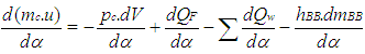 | (1) |
where = change of the internal energy in the cylinder.
 = piston work.
 = fuel heat input.
 = wall heat losses
 = enthalpy flow due to blow-by
 = blow-by mass flowThe first law of thermodynamics for high pressure cycle states that the change of internal energy in the cylinder is equal to the sum of piston work, fuel heat input, wall heat losses and the enthalpy flow due to blow-by.In order to solve this equation, models for the combustion process and the wall heat transfer, as well as the gas properties as a function of pressure, temperature, and gas composition are required.Together with the gas equation
 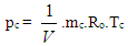 | (2) |
Establishing the relation between pressure, temperature and density, Eq. 2 for in-cylinder temperature can be solved using a Runge-Kutta method. Once the cylinder gas temperature is known, the cylinder gas pressure can be obtained from the gas equation.
2.2. Combustion Model
Air Requirement and Heating Value modeling is given below.
2.2.1. Stoichiometric Air-Fuel Mixture
The following equation for the stoichiometric air requirement specifies how much air is required for a complete combustion of 1 kg fuel: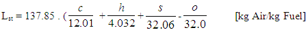 | (3) |
2.2.2. Lean Mixture
For lean combustion, the total heat supplied during the cycle can be calculated from the amount of fuel in the cylinder and the lower heating value of the fuel.
2.2.3. Rich Mixture
In rich air fuel mixture combustion, the total heat supplied during the cycle is limited by the amount of air in the cylinder. The fuel is totally converted to combustion products even if the amount of air available is less than the amount of stoichiometric air.
2.2.4. Heating Value
The lower heating value is a fuel property and can be calculated from the following formula: | (4) |
2.2.5. Heat Release Approach
Vibe Two ZoneThe rate of heat release and mass fraction burned is specified by the Vibe function given by equation No.5 below.The first law of thermodynamics is applied separately to the burned and unburned mixture while assuming that the temperatures of these two mixtures is different.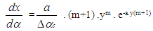 | (5) |
 | (6) |
 | (7) |
The integral of the vibe function gives the fraction of the fuel mass which was burned since the start of combustion: | (8) |
2.3. Gas Exchange Process
Basic EquationThe equation for the simulation of the gas exchange process is also the first law of thermodynamics: | (9) |
The variation of the mass in the cylinder can be calculated from the sum of the in-flowing and out-flowing masses: | (10) |
2.4. Piston Motion
Piston motion applies to both the high pressure cycle and the gas exchange process.For a standard crank train the piston motion as a function of the crank angle α can be written as: | (11) |
 | (12) |
2.5. Heat Transfer
The heat transfer to the walls of the combustion chamber, i.e. the cylinder head, the piston, and the cylinder liner, is calculated from: | (13) |
In the case of the liner wall temperature, the axial temperature variation between the piston TDC and BDC position is taken into account: | (14) |
 | (15) |
For the calculation of the heat transfer coefficient, the Woschni 1978 heat transfer model is used.
2.5.1. Woschni Model
The woschni model published in 1978 for the high pressure cycle is summarized as follows: | (16) |
C1 = 2.28+0.308.cu/cmC2 = 0.00324 for DI enginesFor the gas exchange process, the heat transfer coefficient is given by following equation: | (17) |
2.6. Fuel Injector
The fuel injector model is based on the calculation algorithm of the flow restriction. This means that the air flow rate in the fuel injector depends on the pressure difference across the injector and is calculated using the specified flow coefficients. For the injector model, a measuring point must be specified at the location of the air flow meter. In this case the mean air flow at the air flow meter location during the last complete cycle is used to determine the amount of fuel. As is the case for continuous fuel injection, the fuelling rate is constant over crank angle.
2.7. Pipe Flow
The one dimensional gas dynamics in a pipe are described by the continuity equation  | (18) |
the equation for the conservation of momentum | (19) |
and by the energy equation | (20) |
The wall friction force can be determined from the wall friction factor 
 | (21) |
Using the Reynold’s analogy, the wall heat flow in the pipe can be calculated from the friction force and the difference between wall temperature and gas temperature: | (22) |
During the course of numerical integration of the conservation laws defined in the Eq.20, Eq.21 and Eq.22, special attention should be focused on the control of the time step. In order to achieve a stable solution, the CFL criterion (stability criterion defined by Courant, Friedrichs and Lewy) must be met: | (23) |
This means that a certain relation between the time step and the lengths of the cells must be met. The time step to cell size relation is determined at the beginning of the calculation on the basis of the specified initial conditions in the pipes. However, the CFL criterion is checked every time step during the calculation. If the criterion is not met because of significantly changed flow conditions in the pipes, the time step is reduced automatically.An ENO scheme is used for the solution of the set of non-linear differential equations discussed above. The ENO scheme is based on a finite volume approach. This means that the solution at the end of the time step is obtained from the value at the beginning of the time step and from the fluxes over the cell borders.
2.8. Knock Model
Ignition Delay and Octane Number RequirementAVL Boost uses the following equation based model proposed by Hires etal. for the calculation of ignition delay in combustion. 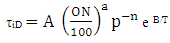 | (24) |
where 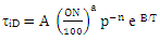
 ignition delayON = Octane Number RequirementA = 17.68 msB = 3800 Ka = 3.402n = 1.7
3. Methodology Used in Present Investigations
The computational methodology was preferably used for present investigations as the experimental investigations involve lot of time for developing a suitable test rig facility. Also experimental investigations have more constraints and limitations. The computational research methodology was used for investigating the for possible use of methanol as an alternative fuel in petrol based spark ignition engine with its commercial octane rating as upper limit for all design and operating parameters based investigations. Most of the research papers available present the experimental investigations for the spark ignition engines using gasoline as a base fuel and repeating the tests with various blends of methanol with gasoline fuels. Some researchers have done experimental investigations with neat methanol in high compression ratio based engines fitted with spark ignition systems. Their aim was to use the high octane rating of methanol and possibly to overcome the cold start problem with methanol. The computational investigations done and presented in this paper involve the thermodynamic design and optimization of an existing naturally aspirated spark ignition engine with neat methanol. Boundary conditions for these investigations were the octane ratings and other physical and chemical properties of the commercially available methanol.Model for a single cylinder spark ignition engine was created in AVL BOOST software using its graphical user interface. The thermodynamic models for heat transfer, combustion, frictional power etc available in the software were selected for simulating the results. The thermodynamic properties temperature was computed in the cylinder on an incremental crank angle basis by solving the energy equation for closed system when both the valves were closed and as an open system when one or both the valves were open. Next the pressure was calculated for each crank angle using the equation of state and the value of temperature computed earlier.The computed values of pressure and temperature of the working medium in the cylinder were used, in the knock model, during the combustion process for computing the octane demand of the engine for methanol as well as gasoline. In addition to temperature and pressure many more thermodynamic properties of the working medium in the cylinder and the engine manifolds were computed using various laws of thermodynamics. This data was used to compute other engine related parameters like heat transfer, combustion generated pollutants, indicated power, frictional power loss and finally the brake power available at the engine crank shaft.The computed values of the thermodynamic properties are also used to incorporate the effects of manifold components like muffler etc on the overall performance of the engine.
4. Results and Discussions
4.1. Effect of Speed on Octane Number Requirement.
The Fig.1 below shows that octane number requirement for both petrol and methanol fuels vary with respect to speed. The octane demand of the engine for both the fuels is maximum at lowest speed and slopes down to minimum at maximum engine rated power speed. The maximum octane requirement of the engine in the methanol mode is lower than the octane rating of the commercially available methanol. 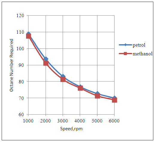 | Figure 1. Effect of Speed on Octane Number Required By the Engine |
4.2. Effect of Speed on Engine Power
The Fig.2 below shows that the power developed by the engine increases with speed with both petrol and methanol fuels. The engine develops slightly lesser power in the methanol mode as compared to the petrol mode since the combined effects of heating value and the stoichiometric air-fuels ratios, for both the fuels under similar engine design and operating conditions, are less favorable in case of the methanol fuel. 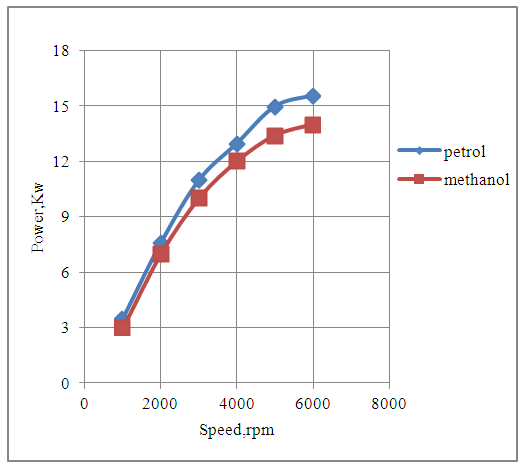 | Figure 2. Effect of Speed on Power |
4.3. Effect of Speed on Engine Torque.
The Fig.3 below shows that the torque developed by the engine varies over the entire range of speed of the engine for both petrol and methanol fuels. The torque developed by the engine with methanol is slightly lesser as compared to that developed with petrol fuel since the combined effects of the heating value and the stoichiometric air-fuel ratio of the two fuels are less favorable with methanol as fuel. The engine produces maximum torque at the speed of 2000rpm with each fuel under consideration because the overall combustion characteristics of the engine are the best at this speed.  | Figure 3. Effect of Speed on Torque |
4.4. Effect of Speed on Brake Specific Fuel Consumption.
The Fig.4 below shows the effect of speed on the brake specific fuel consumption of the engine in the petrol and methanol modes. The brake specific fuel consumption varies with respect to speed, for either of the two fuels, and is minimum at the speed of maximum rated torque.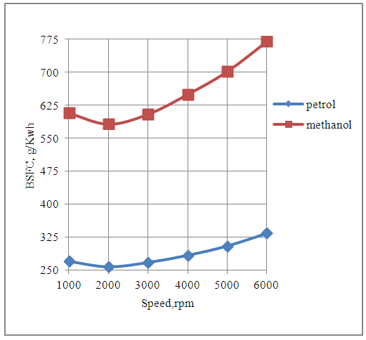 | Figure 4. Effect of Speed on Brake Specific Fuel Consumption |
The brake specific fuel consumption of the engine is higher with methanol fuel as compared to the petrol fuel. This is because for the same displacement volume of the engine under consideration, the mass of the methanol fuel consumed per cycle is more than double the mass of the petrol fuel consumed per cycle, under rich mixture conditions. Further the comparatively lesser magnitude of the heating value of methanol also contributes. The overall combined effect of the respective fuel consumptions per cycle and the heating values of the two fuels are less favorable for methanol fuel.
4.5. Effect of Speed on CO Emissions
The Fig.5 below shows the effect of speed on CO emissions produced by the engine with petrol and methanol as alternative fuels. It is seen that the engine produces more CO emissions with methanol fuel as compared to the petrol fuel. This is because the methanol consumption per unit of energy production by the engine is more than double as compared to the petrol consumption. 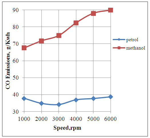 | Figure 5. Effect of Speed on CO Emissions |
4.6. Effect of Speed on HC Emissions
The Fig.6 below shows the effect of speed on the unburned hydrocarbon emissions produced by the engine in the methanol and the petrol modes.It is seen that In general the engine produces more HC emissions with methanol as compared to petrol because the methanol consumption per cycle is more than double as compared to petrol consumption per cycle. This is because the magnitude of the operating value of the air-fuel ratio for rich operation of the engine with methanol is less than half of that with petrol as its fuel. The HC emissions produced by the engine are least at the speed of maximum rated torque. This is because the design and the operating conditions of the engine are more favorable for combustion at this speed. 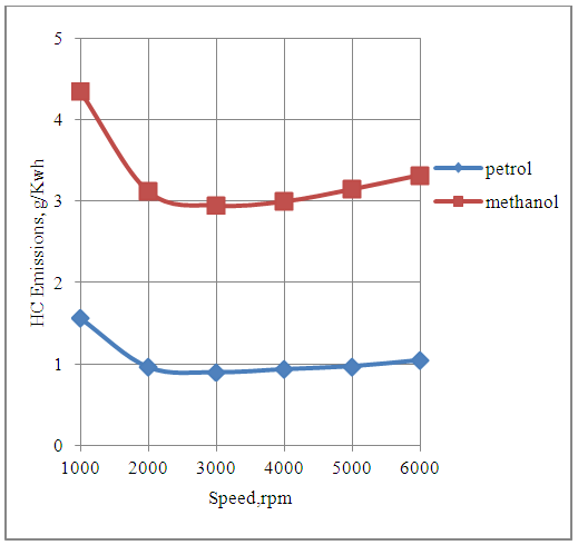 | Figure 6. Effect of Speed on Hydrocarbon Emissions |
4.7. Effect of Speed on NOx Emissions.
The Fig.7 below shows the effect of speed on the NOx emissions produced by the engine with petrol and methanol fuels.The engine produces more amount of NOx emissions in the petrol mode as compared to methanol mode. This is because the temperatures produced by the engine during each cycle are higher with petrol fuel as compared to methanol fuel due to higher heating value of petrol.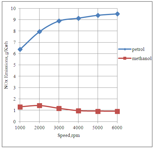 | Figure 7. Effect of Speed on NOx Emissions |
4.8. Effect of Speed on Exhaust Gas Temperature
The Fig.8 below shows the effect of speed on the exhaust gas temperature produced by the engine with both petrol and methanol fuels.The exhaust gas temperatures are higher in the petrol mode as compared to methanol mode above the speed of 2000rpm. This is due to the higher heating value of petrol as compared to methanol. The exhaust gas temperatures of the engine with methanol is higher than that with petrol up to the engine speed of 2000rpm. This is because of the higher methanol consumption per cycle as compared to petrol consumption per cycle up to this speed. 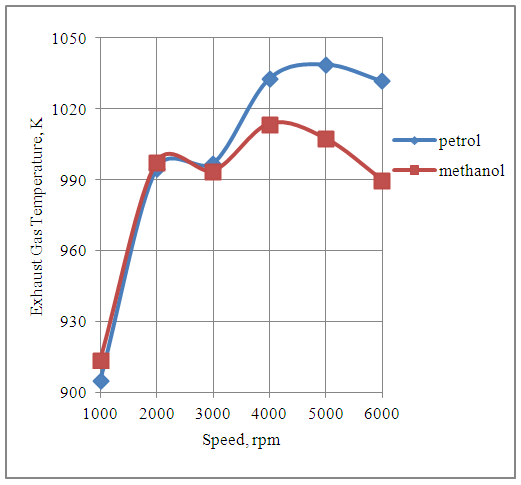 | Figure 8. Effect of Speed on Exhaust Gas Temperature |
5. Conclusions
1. The Octane Demand of the engine will help in the selection of both methanol and gasoline being commercialized in the market. This will further help in optimizing the spark timing of the engine for achieving the maximum brake torque conditions for the same.2. Methanol can successfully be used as a fuel in the spark ignition engines from the thermodynamic analysis and optimization point of view.3. The power and the torque produced by the engine in the methanol mode are comparable to the power and torque produced in the petrol mode.4. The engine seems to be more economical with petrol consumption as compared to methanol consumption from thermodynamics point of view. 5. The engine produces more CO and HC emissions in the methanol mode as compared to that produced in the petrol mode.6. The NOx emissions produced by the engine with methanol fuel are lesser than that produced with petrol fuel.
ACKNOWLEDGEMENTS
Author is thankful to AVL Austria and its unit AVL India Ltd Gurgaon for providing BOOST engine simulation software with free license for academic research purposes.
Appendix-A
Nomenclaturea = speed of sound, m/secA = pipe cross-section, m2Aeff = effective flow area, m2Ai = surface area (cylinder head, piston, liner), m2AFCP = air fuel ratio of combustion productsAgeo = geometrical flow area, m2c = mass fraction of carbon in the fuelcV = specific heat at constant volume, J/Kg.Kcp = specific heat at constant pressure, J/Kg.KCm = mean piston speed, m/secCu = circumferential velocity, m/seccu = circumferential velocity, m/secD = cylinder bore, mdmi = mass element flowing into the cylinder, kgdme = mass element flowing out of the cylinder, kgdvi = inner valve seat diameter (reference diameter), m = blow-by mass flow, kg/degree of crank anglee = piston pin offset, mE = energy content of the gas
 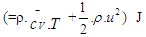 f = fraction of evaporation heat from the cylinder chargeFR = wall friction force, Nh = mass fraction of hydrogen in the fuelhBB = enthalpy of blow-by, J/Kghi = enthalpy of in-flowing mass, J/Kghe = enthalpy of the mass leaving the cylinderHu = lower heating value, J/Kgk = ratio of specific heatsl = con-rod length, mm = shape factor
 = mass flow rate, kg/secmc = mass in the cylinder , kgmev = evaporating fuel, kgmpl = mass in the plenum, kgn = mass fraction of nitrogen in the fuelo = mass fraction of oxygen in the fuelp = static pressure, barP01 = upstream stagnation pressure, barPc,o = cylinder pressure of the motored engine ,barPc,1 = pressure in the cylinder at IVC, barppl = pressure in the plenum, barpc = cylinder pressure, barp2 = downstream static pressure, barqev = evaporation heat of the fuel, J/kgqw = wall heat flow, JQ = total fuel heat input, JQF = fuel energy, JQwi= wall heat flow (cylinder head, piston, liner), Jr = crank radius, mR0 = gas constant, J/mol.Ks = piston distance from TDC, mt = time, secT = temperature, KTc,1 = temperature in the cylinder at intake valve closing (IVC), KTc = gas temperature in the cylinder, KTwi = wall temperature (cylinder head, piston, liner), KTL = liner temperature, KT L,TDC = liner temperature at TDC position, KT L,BDC = liner temperature at BDC position, KTw = pipe wall temperature, KT01= upstream stagnation temperature, Ku = specific internal energy, J/Kgu = flow velocity, m/secV = cylinder volume, m3V = cell volume (A.dx), m3VD = displacement per cylinder, m3w = mass fraction of water in the fuelx = relative stroke (actual piston position related to full stroke)α = crank angle, degreesαo= start of combustion, crank angle degreesΔαc= combustion duration, crank angle degreesαw = heat transfer coefficient, J/m2.Kρ = density, kg/m3μσ = flow coefficient of the portψ = crank angle between vertical crank position and piston TDC position, degrees
 = wall friction coefficientΔt = time step, secΔx= cell length, m
Table 1
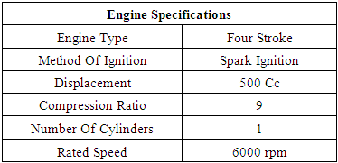 |
| |
|
Table 2. Physical and Chemical Properties of Petrol and Methanol [14]
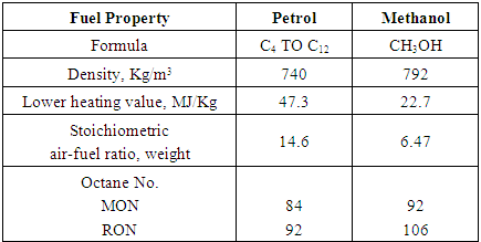 |
| |
|
References
| [1] | Michael Saccullo, Timothy Benham PhD, Ingemar Denbratt, “Dual Fuel Methanol and Diesel Direct Injection HD Single Cylinder Engine Tests”, SAE Technical Paper 2018-01-0259, 2018. |
| [2] | Duc-Khah Nguyen, tim Van Craeynest, Thomas Pillu, Jakob coulier and Sebastian Verhelst, “Downsizing Potential of Methanol Fueled DISI Engine with Variable Valve Timing and Boost Control”, SAE Technical Paper 2018-01-0918, 2018. |
| [3] | Mateusz Pucilowski, Mehdi Jangi, Sam Shamun, Martin Tuner, Xue-Song Bai, “The Effect of Injection Pressure on the NOx Emission Rates in a Heavy-Duty DICI Engine running on Methanol”, SAE Technical Paper 2017-01-2194, 2017. |
| [4] | Chen, Z; Zhang, T; Duan, Q. et al;, ”Experimental Investigations of Combustion Characteristics in a Heavy Duty Natural Gas Engine under Light Load with Methanol Addition”, SAE Technical Paper 2017-01-2268, 2017. |
| [5] | Leonid Tartakovsky, Ran Amiel, V. Baibikov, R. Fleischman, M. Gutman, A. Poran, M. Veinblat; “SI Engine with Direct Injection of Methanol Reforming Products – First Experimental Results” SAE Technical Paper 2015-32-0712, 2015. |
| [6] | Erik Svensson, Changle Li, Sam Shamun, Bengt Johansson, Martin Tuner, Cathleen Perlman, Harry Lehtiniemi and Fabian Mauss, “Potential Levels of Soot, NOx, HC and CO for Methanol Combustion”, SAE Technical Paper 2016-01-0887, 2016. |
| [7] | Fan Zhang, Shijin Shuai, Jianxin Wang and Zhen Wang, “Influence of Methanol Gasoline Blend Fuel on Engine and Catalyst Performance”, SAE Technical Paper 2009-04-20, 2009. |
| [8] | Sukho Jung, Masahiro Ishida, Hironobu Ueki, Daisaku Sakguchi; “Ignition Characteristics of Methanol and Natural Gas in a HCCI Engine Assisted by DME”, SAE Technical Paper 2007-01-1863, 2007. |
| [9] | Robert Q Riley, “Alternative Cars in the 21st Century” SAE International Publication, 2004. |
| [10] | Ramadan, B., Hamady, F., Gracy, C., Hellman, K. and Harold, S., "Numerical Evaluation of A Methanol Fueled Directly-Injected Engine" SAE Technical Paper 2002-01-2702, 2002. |
| [11] | Brusstar, M. and Gracy, C., "High Efficiency with Future Alcohol Fuels in a Stoichiometric Medium Duty Spark Ignition Engine" SAE Technical Paper 2007-01-3993, 2007. |
| [12] | Zhang Fan et al., “A detailed oxidation mechanism for the prediction of formaldehyde emission from methanol-gasoline SI engines”, Proceedings of the Combustion Institute, Elsevier, 2011. |
| [13] | AVL LIST Gmbh, AVL BOOST Theory, Version 2015. |
| [14] | John B. Heywood, “Internal Combustion Engine Fundamentals”, McGRAW HILL Book Company, 1989. |

 Abstract
 Reference
 Full-Text PDF
 Full-text HTML