Rakesh R.1, Manjunath H. N.2, Krupa R.2, Sushanth H. Gowda3, Kiran Aithal S.2
1Department of Mechanical Engineering, R N S Institute of Technology, Bangalore, India
2Department of Mechanical Engineering, NMIT, Bangalore, India
3Department of Mechanical Engineering, SJEC, Mangaluru, India
Correspondence to: Sushanth H. Gowda, Department of Mechanical Engineering, SJEC, Mangaluru, India.
| Email: |  |
Copyright © 2017 Scientific & Academic Publishing. All Rights Reserved.
This work is licensed under the Creative Commons Attribution International License (CC BY).
http://creativecommons.org/licenses/by/4.0/

Abstract
To Improve the Coefficient of Performance (COP), it is required to decrease the Compressor Work and increase the Refrigerating Effect. Experimental analysis on vapour compression refrigeration (VCR) system with R134A (Tetra Fluro Ethane) refrigerant was done and their results were recorded. The effects of the main parameters of performance analysis are mass flow rate of refrigerant, suction pressure of compressor, delivery pressure of compressor, temperature of evaporator and condenser. The results from vapour compression refrigerant plant was taken where the variables like suction pressure of compressor, delivery pressure of compressor, temperature of evaporator and condenser were noted and coefficient of performance (COP) was calculated. The results obtained will be validated through CFD simulation. Further diffuser has been introduced in between compressor and condenser so that power input to the compressor has been reduced there by enhancing COP. The enhancement is done through CFD simulation; Modeling and meshing is done in ICEMCFD, analysis in CFX and post results in CFD POST.
Keywords:
Diffuser, Refrigerator, Performance, Vapour Compression Refrigeration System
Cite this paper: Rakesh R., Manjunath H. N., Krupa R., Sushanth H. Gowda, Kiran Aithal S., A Study on Enhancing COP in VCR by Providing Diffuser in between Condenser and Compressor, Energy and Power, Vol. 7 No. 5, 2017, pp. 142-148. doi: 10.5923/j.ep.20170705.04.
1. Introduction
In thermodynamics Refrigeration is the major application area, in which the heat is transferred from a lower temperature region to a higher temperature region. The devices which produce refrigeration are known as Refrigerators and the cycle on which it operates are called refrigeration cycles. Vapour compression refrigeration cycle is the most regularly used refrigeration cycle in which the refrigerant is alternately vaporized and condensed and in the vapor phase it is compressed. Gas refrigeration cycle is the well-known refrigeration cycle in which cycle refrigerant remains in the gaseous phase throughout the cycle. Cascade refrigeration are the other refrigeration cycles discussed in this chapter; absorption refrigeration is the one more refrigeration cycle which is used where the refrigerant is dissolved in liquid before it is compressed. One more refrigeration in which refrigeration is produced by passing the electric current through two dissimilar materials is called as the thermoelectric refrigeration. Neeraj Upadhyay [1] found that COP of Vapor Compression Cycle is increased by lowering the power consumption /work input or increasing the refrigerating effect. By using sub-cooling and using a diffuser at condenser inlet refrigerating effect increases and power consumption or work input decreases. Thus performance of cycle is increased. High velocity refrigerant has various serious affect on vapor compression refrigeration system such as liquid hump, undesirable splashing of the liquid refrigerant in the condenser and damage to the condenser tubes by vibration, pitting and erosion R. Reji Kumar et.al [2] found that the R600a refrigerant and mineral oil mixture with nanoparticles worked normally. Freezing capacity of the refrigeration system will be more with mineral oil + alumina nanoparticles oil mixture compared the system with POE oil. When the nanolubricant is used instead of conventional POE oil the power consumption of the compressor reduces by 11.5% when the conventional POE oil is replaced with nanorefrigerant the coefficient of performance (COP) of the refrigeration system also increases by 19.6%.M. Krishna Prasanna, and P S Kishore [3] found that when the heat exchanger is used with vapour compression refrigeration system the refrigeration effect of the system is increases up to 16%, and the COP (coefficient of performance) of the system also increases up to 16%. When the heat exchanger is used with vapour compression refrigeration system mass flow of refrigerant (mR) is reduced up to 14%. Heat available for desuperheating (Q) increases as the evaporation temperature decreases. So by attaching heat exchanger to the vapour compression refrigeration system and regulating water into heat exchanger, outlet temperature of the water (t2) in heat exchanger increases. That hot water can be used for useful purpose. When the heat exchanger is used with vapour compression refrigeration system when the heat exchanger is used with vapour compression refrigeration system power required to run the compressor is reduced up to 14%.J.K. Dabas et.al [4] found that, in most of the practical refrigeration applications, a vapour compression refrigeration system works in transient conditions because the temperature surrounding the evaporator and so the temperature difference across the wall of evaporator tubes falls continuously with the working of system itself. With this the heat transfer rate in evaporator or the refrigeration rate also falls but not with same pace. One reason is that with the constant reduction in evaporator pressure during cooling of a fixed mass, more and more refrigerant liquid accumulates in the evaporator causing multifold rise in overall heat transfer coefficient. Another reason behind is that as the heat transfer rate reduces, evaporation rate and so the pressure and temperature of refrigerant in the evaporator also reduces, which maintain the temperature difference causing heat transfer in evaporator In this way the refrigeration sustains even at very low temperature of brine surrounding evaporator tubes because the system keeps on adjusting itself naturally under the transient conditions over evaporator. The pressure in the evaporator and mass flow rate of the refrigerant keeps on decreasing and the specific compressor work keeps on increasing. Because of this the performance of system deteriorates continuously. The limiting condition is that when the refrigerant flow rate reduces too much due to reduction in evaporation rate and the evaporator tends to fill with refrigerant liquid. In this condition there may be the chances of liquid suction by compressor. The compressor must be stopped before this limiting condition but simultaneously the required temperature of brine must also be achieved. A capillary tube of shorter length ensure higher Coefficient of Performance (COP) but the limiting condition would reach fast while increase in the length of capillary tube delays the limiting condition but gives lesser Coefficient of Performance (COP). A vapour compression refrigeration system with known internal and external irreversibility can be balanced and designed optimally between evaporator temperature and static values of condenser. But the system performance deteriorates from the optimum value in the transient condition stated above. To give maximum Coefficient of Performance (COP), the capillary tube should be of minimum length but it should also be sufficient to maintain the required low evaporator pressure and minimum value of condenser pressure in the later portion of cooling job. A refrigeration system should be designed more accurately by its simulation in real life transient conditions. However to find accurate transient models for each of the component is a challenging task, an alternate suggestion is to use a lesser length of capillary tube initially and then shifting to larger length later on with the help of some automatic temperature sensing device or valve.Lucia Vîlceanu and Mihaela Flori [5] found that, thermodynamic performance of a refrigeration system is defined by evaluating the efficiency of cooling, which permit the quantitative assessment of heat losses, qualitatively described by the second principle of thermodynamics. If the evaporating and condensing temperatures are measured at selected locations on the refrigeration system, the refrigeration cycle may be drown in log(p)‐h diagram using Cool Pack program. This program permits the designing, sizing, analysing and optimization of refrigeration cycles. When the system efficiency is compared with with an ideal machine that works after reversed Carnot cycle, then only a real appreciation of the quality of thermodynamic refrigeration cycle can be properly assessed. The differences may arise from pressure loss in the system elements with the exception of mechanical compression, heat loss between the system and the environment; losses due to vapors which deviate from perfect gas behavior. All these real irreversible effects influence the system performance involving a quantity of additional energy used by the compressor.R. T. Saudagar and Dr. U. S. Wankhede [6] found that high velocity refrigerant has various serious affects on vapor compression refrigeration system such as liquid hump, undesirable splashing of the liquid refrigerant in the condenser, starving in evaporator and damage to the condenser tubes by vibration, pitting and erosion. To reduce high velocity of refrigerant some amount of kinetic energy is to be converted into pressure energy without work consumption. Diffuser is such a device which can do the same.P. Thangavel et.al [7] found that R134a and R12 are halogenated compounds which will cause harmful effects to the environment in terms of global warming and ozone layer depletion. So the attention is focused on alternative refrigerants for vapour compression refrigeration system with hydrocarbon refrigerants. R290 and R600a offer many desirable characteristics such as low operating pressure, mass flow rate and discharge temperature. The Coefficient of Performance (COP) of these mixtures is close to the conventional refrigerants. Hence propane and isobutene with the concentration of 50% each is the suitable refrigerant among all the investigated refrigerants for vapour compression system. This mixture provides better performance in terms of pressure ratio, volumetric efficiency, heat rejection and Coefficient of Performance (COP) for the vapour compression refrigeration system. Hydrocarbon refrigerants are having less impact on the environment in terms of global warming. In domestic refrigerators and industrial refrigeration systems, the mixture of R290 & R600a can be used as alternate refrigerant instead of R12 and R134a. A. Baskaran and P. Koshy Mathews [8] found that, Coefficient of Performance (COP) for R429A, R430A, R431A are 0.683%, 3.324% 8.789%lower and it is higher for R435A by 1.229% in comparison to R152a. Pressure ratio required for R430A, R431A and R435A are 10.098%, 31.869%, 7.409% lower than R152a. So thus the size of compressor required for R152a is higher. Volumetric Refrigerating capacity for R429A is 0.112% lower and 5.548%, 69.979% 7.398% higher for R430A, R431A R435Ain comparison to R152a. Hence, small size compressor is sufficient while using the above blends. Discharge temperature for R429A, R430A, R431A and R435A are 15.469%, 14.254%, 18.232%, and 2.541% lower than R152a. Hence, while using above blends for substitute to R152a compressor life is increased. Compressor power required for R429A, R430A, R431A are 0.879%, 3.516%, 9.67% higher and 1.098% lower for R435A. Hence, less compressor power is required while using R435A for substitute to R152a. Condenser duty for R429, R431A, and R435A are 20.312%, 1.189%, 31.697% higher and 6.646% lower for R430A. Hence, less Condenser duty while using R430A for substitute to R152a. Refrigeration effect for R429A, R435A is 20.056%, 32.198 % higher and 7.639%, 1.764% lower for R430A R431A. Hence, and more refrigeration effect is obtained while using R435A for substitute to R152a. Compressor work for R429, R431A and R435A are 20.76%, 7.576%, 30.477% higher and 4.556% lower for R430A.Hence, less compressor work is required while using R430A for substitute to R152a. Refrigerant mass flow rates for R430A, R431A are 8.274%, 1.798% higher and 16.705%, 24.353% lower for R429A, R435A. Hence, and refrigerant mass flow is decreased while using R429A, R435A for substitute to R152a.
2. Experimental Setup
SpecificationsRefrigerator Capacity – 220 lts.Pipe Diameter of the Evaporator – 11 mm = 0.011 mLength of the evaporator coil – 1539 mm = 1.539 mObservationsT1 = Temperature at Compressor Inlet, (oC)T2 = Temperature at Compressor Outlet, (oC)T3 = Temperature at Condenser Outlet, (oC) T4 = Temperature at Evaporator Inlet, (oC)P1 = Upstream pressure of the Compressor (Kg/cm2)P2 = Downstream pressure of the Compressor (lb/in2)Refrigerant used - R134A (Tetra Fluoro Ethane)Suction pressure of the compressor = Low PressureDischarge pressure of the compressor = High PressureSuction temperature of the compressor= Outlet temperature of the evaporatorDischarge temperature of the compressor = Temperature at Compressor OutletEvaporator temperature = Temperature at Evaporator InletAfter condensation temperature = Temperature at Condenser Outlet.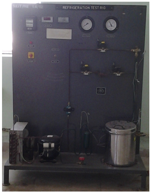 | Figure 1. Experimental set up (Refrigeration Test Rig) |
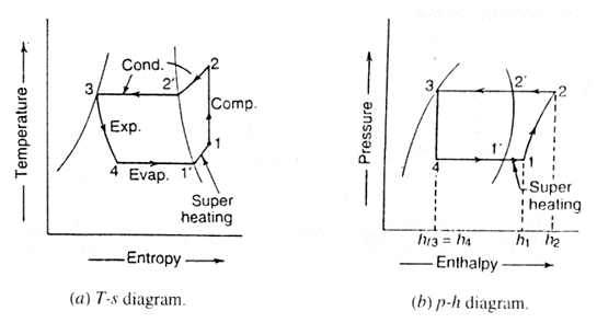 | Figure 2. Actual Vapour Compression Cycle |
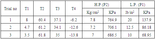
CALCULATIONS FOR COP:Table 1. Experiment results
 |
| |
|
Values of Enthalpy, Saturation temperature were taken from the table for R134A.It is found for the trial 1 that COP of the refrigerator is 3.83 refrigerator capacity is 0.77 kJ/s, Refrigeration effect is 171.835 KJ/Kg, mass flow rate 0.00448 Kg/s and heat flux is 1146 W/m2.
3. Evaporator Flow Analysis
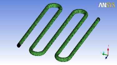 | Figure 3. Modeling and meshing |
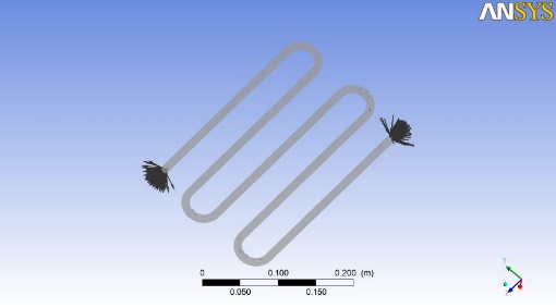 | Figure 4. Model Imported From ICEM CFD and Boundary Condition Given |
4. Experimental Validation
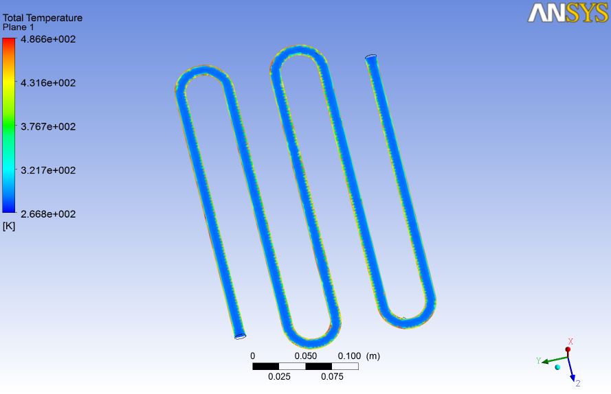 | Figure 5. Temperature Plane |
It is seen from figure 5 that temperature is increased from inlet to outlet in evaporator which is a heat exchanger which clearly validates the experimental results.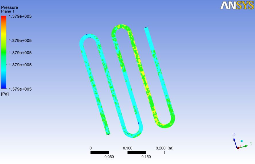 | Figure 6. Pressure Plane |
It is seen from the figure 6 that pressure plane pressure is constant which indicates that constant pressure process is taking place.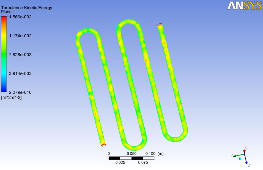 | Figure 7. Turbulence Kinetic Energy |
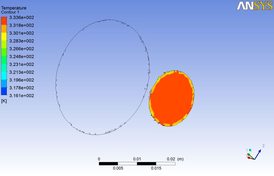
It is seen from figure 7 that turbulence kinetic energy is more towards wall region. It is seen from the figure that inlet temperature is 266.8K which clearly validates the result taken from experiments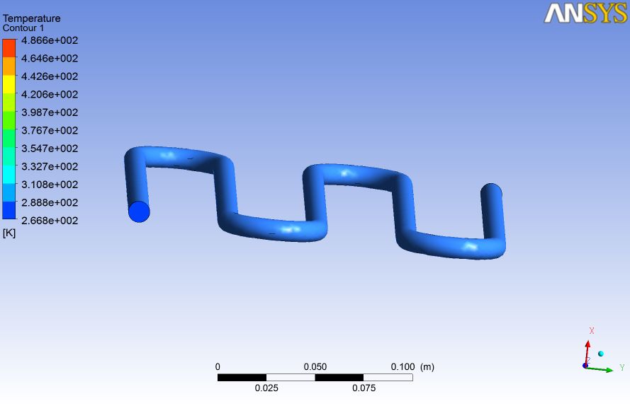 | Figure 8. Temperature Contour inlet |
It is seen from the figure 9 that outlet temperature is 281K which clearly validates the result taken from experiments. 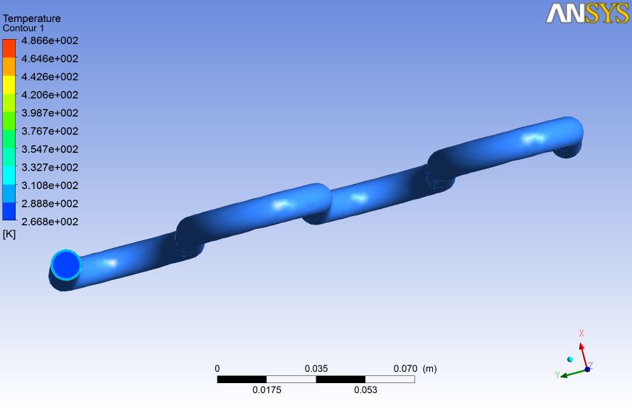 | Figure 9. Temperature Contour outlet |
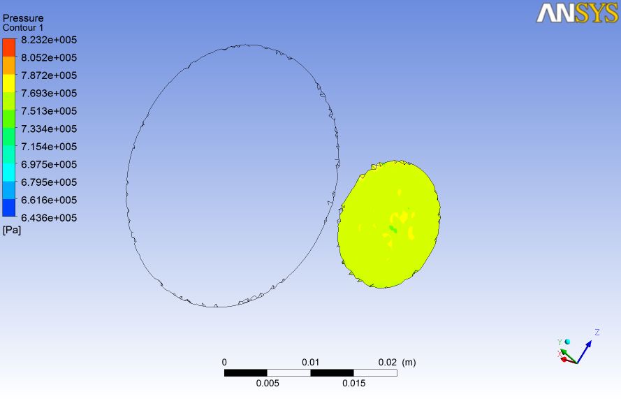
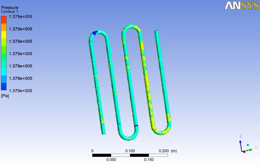 | Figure 10. Pressure Contour |
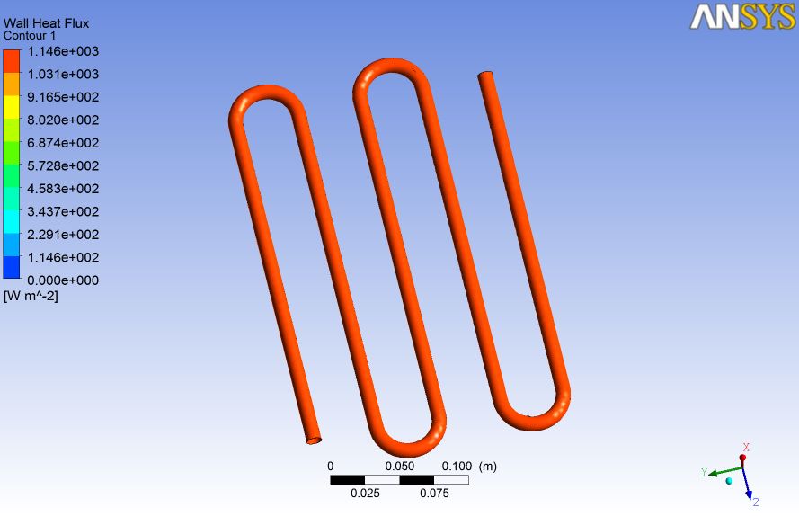 | Figure 11. Wall Heat Flux Contour |
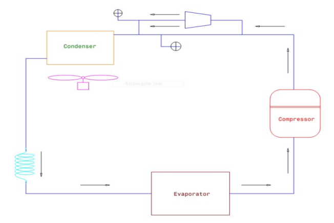 | Figure 12. Vapour Compression Refrigeration Cycle Along With Diffuser Block Diagram |
Enhancement of cop by providing diffuser between compressor and condenser with divergence angle of diffuser 15°.
5. Results and Discussions
Inner diameter = 15 mmANGLE OF divergence = 15°Length of diffuser = 30 mm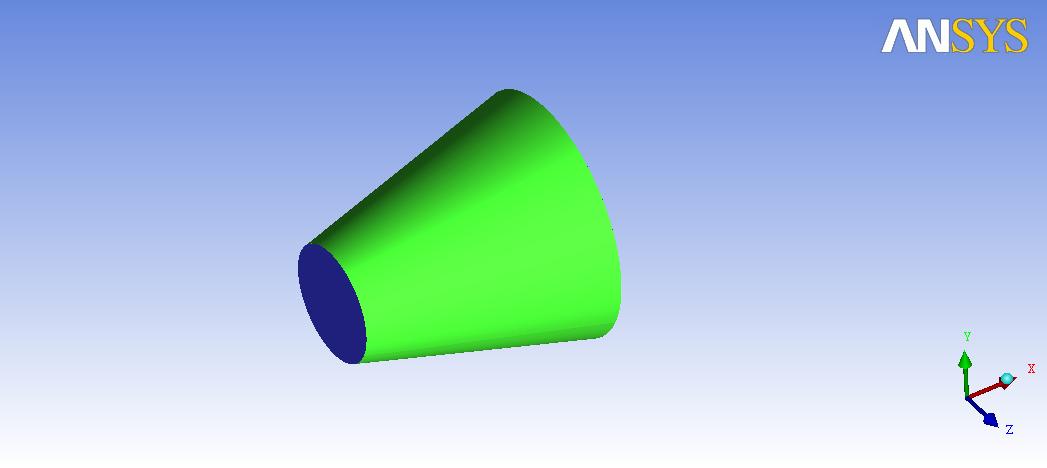 | Figure 13. Diffuser Model |
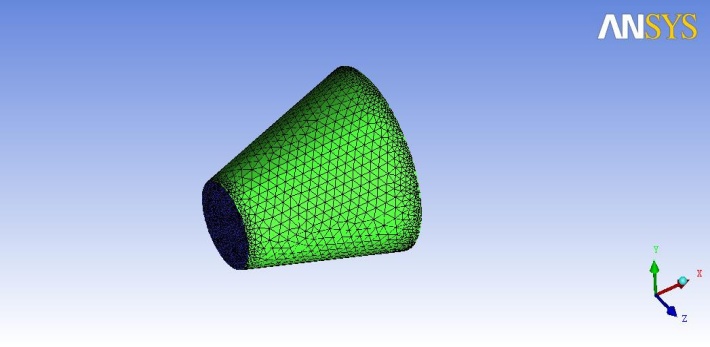 | Figure 14. Meshing of Diffuser |
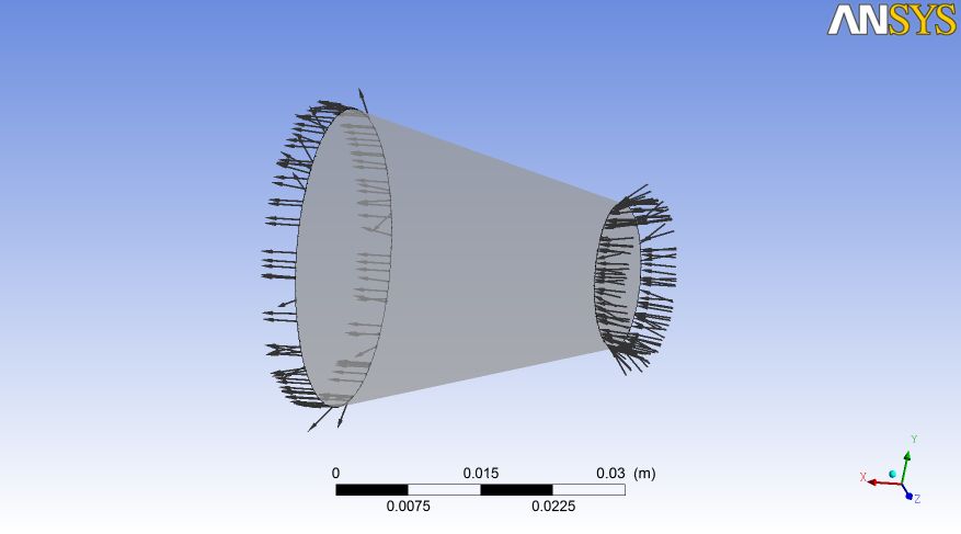 | Figure 15. Imported from ICEMCFD to CFX for Analysis |
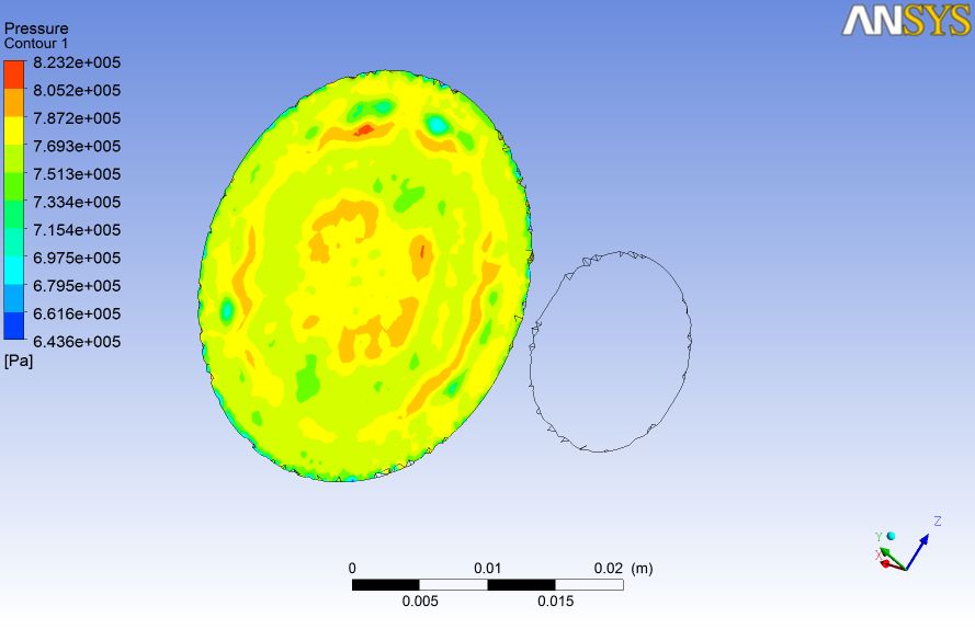
 | Figure 16. Inlet Pressure of the diffuser is validated |
 | Figure 17. Outlet Pressure of the diffuser is validated |
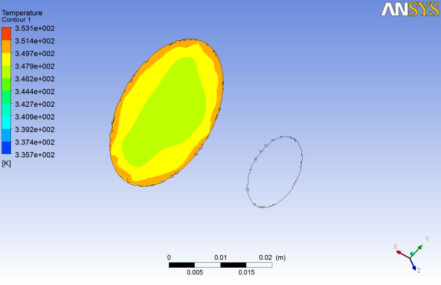
 | Figure 18. Inlet Temperature of the diffuser is validated |
 | Figure 19. Outlet Temperature of the diffuser is validated |
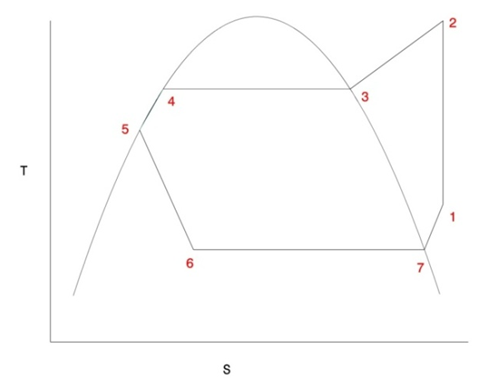 | Figure 20. Actual Vapour Compression Cycle (T-S diagram) |
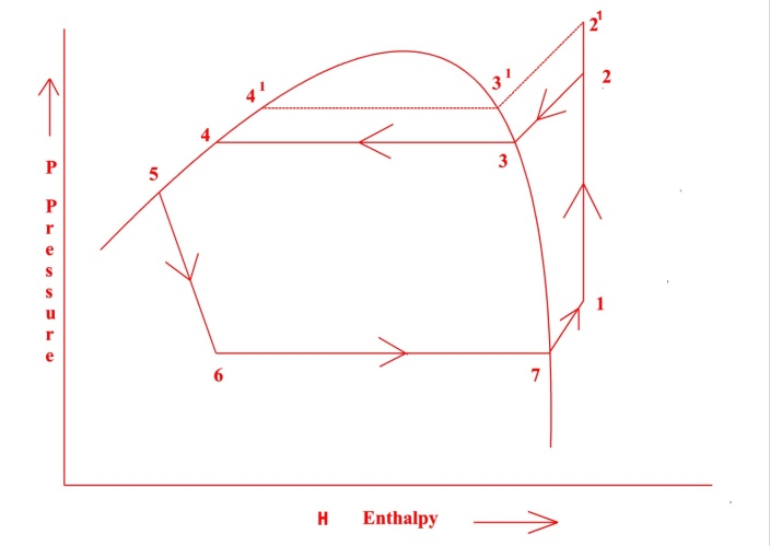 | Figure 21. Pressure Enthalpy diagram |
When diffuser added pressure rises from 2 to 21, if diffuser is absent then compressor take additional power input to reach 21. It is found that power input to compressor with and without diffuser is 0.2 kW and 0.14 kW, COP is found to be 5.55 with diffuser enhancing COP by 31%. With the addition of diffuser pressure inlet of refrigerant to the condenser is increased. Since work input to the compressor is decreased. With the addition of diffuser Coefficient of Performance (COP) enhancement has been increased by 31% when compared without diffuser. Power input to the compressor obtained without diffuser is 0.2 KW. Power input to the compressor with diffuser obtained is 0.14KW. Finally conclusion drawn is Coefficient of Performance (COP) can be enhanced by placing diffuser.
References
| [1] | N. Upadhyay, "To study the effect of Sub-cooling and Diffuser on the Coefficient of Performance of Vapour Compression Refrigeration System," International Journal of Research in Aeronautical And Mechanical Engineering, vol. 2, no. 6, pp. 40-44, 2014. |
| [2] | K. S. M. N. R Reji Kumar, "Heat transfer enhancement in domestic refrigerator using R600a/mineral oil/nano- Al2O3 as working fluid," International Journal of Computational Engineering Research, vol. 3, no. 4, pp. 42-50, 2013. |
| [3] | "Enhancement of COP in Vapour Compression Refrigeration System," M Krishna Prasanna, P S Kishore, vol. 3, no. 11, 2014. |
| [4] | A. S. K. K. J K Dabas, "Performance Characteristics of “Vapour Compression Refrigeration System” Under Real Transient Conditions," International Journal of Advancements in Technology, vol. 2, no. 4, pp. 584-593, 2011. |
| [5] | Lucia Vîlceanu, "Performance characteristic of vapour compression refrigeration systems,” Annals of Faculty Engineering Hunedoara – International Journal Of Engineering, pp. 145-148, 2012. |
| [6] | D. U. S. W. R. T. Saudagar, "Vapor compression refrigeration system with diffuser at condenser inlet," International Journal of Engineering Research and Development, vol. 1, no. 11, pp. 67-70, 2012. |
| [7] | D. T. C. K. G. P. Thangavel, "Simulation Analysis of Compression Refrigeration Cycle with Different Refrigerants," International Journal of Engineering and Innovative Technology, vol. 2, no. 10, pp. 127-131, 2013. |
| [8] | K. M. Ayyalusamy Baskaran, "Thermodynamic Analysis of R152a and Dimethylether Refrigerant Mixtures in Refrigeration System," Jordan Journal of Mechanical and Industrial Engineering, vol. 9, no. 4, pp. 289-296, 2015. |

 Abstract
 Reference
 Full-Text PDF
 Full-text HTML