Prabjot Singh Virdi1, Mohammed Saahil Khan1, Nelroy Pereira1, Suresh K. V.2, Rolvin S. D’Silva1
1Department of Mechanical Engineering, St Joseph Engineering College - Vamanjoor, Mangaluru, India
2Department of Mechanical Engineering, Alva; s Institute of Engineering and Technology, Moodbidri, India
Correspondence to: Rolvin S. D’Silva, Department of Mechanical Engineering, St Joseph Engineering College - Vamanjoor, Mangaluru, India.
| Email: |  |
Copyright © 2017 Scientific & Academic Publishing. All Rights Reserved.
This work is licensed under the Creative Commons Attribution International License (CC BY).
http://creativecommons.org/licenses/by/4.0/

Abstract
In this work, a centrifugal type impeller has been designed using Ansys software to develop a pressure of 2.9 bar at the mass flow rate of 0.6 kg/s and suitable diffuser has been designed to guide the air flow in required direction using the same software. According to the pressure and mass flow rate available annular type of combustion chamber has been designed to produce suitable temperature. The turbine rotor, having reaction 0.4974 has been designed to produce the power required to run the impeller and the accessories in a single stage utilizing the pressure and temperature available which has greatly reduced the cost of manufacturing. Aerofoil shape required for blade has been developed using Bladegen tool of Ansys software. Impeller and diffuser have been produced using Aluminium by CNC machining. To endure the high temperatures developed, Stainless Steel is used for combustion chamber and produced using basic machining processes. Oil hardened Nickel steel is the material used to manufacture the stator and rotor of a turbine section and it is done using CNC machining process. All the above components have been successfully assembled.
Keywords:
Turbojet Engine, Impeller Design, Turbine Design, Nozzle Design
Cite this paper: Prabjot Singh Virdi, Mohammed Saahil Khan, Nelroy Pereira, Suresh K. V., Rolvin S. D’Silva, Design and Fabrication of Major Components of Turbojet Engine, Energy and Power, Vol. 7 No. 5, 2017, pp. 130-135. doi: 10.5923/j.ep.20170705.02.
1. Introduction
1.1. Principle and Working of a Turbojet Engine
The turbojet is an air breathing jet engine, usually used in aircraft. It consists of a gas turbine with a propelling nozzle. The gas turbine has an air inlet, a compressor, a combustion chamber, and a turbine (that drives the compressor). The compressed air from the compressor is heated by the fuel in the combustion chamber and then allowed to expand through the turbine. The turbine exhaust is then expanded in the propelling nozzle where it is accelerated to high speed to provide thrust. These modern engines use a gas turbine engine core with high overall pressure ratio and high turbine entry temperature and provide a great deal of their thrust with a turbine-power fan stage, rather than with pure exhaust thrust as in a turbojet. These features combine to give a high efficiency relative to a turbojet. All practical air breathing jet engines are internal combustion engines that directly heat the air by burning fuel, with the resultant hot gases used for propulsion via a propulsive nozzle [1, 2]. It mainly works on the principle of Brayton Cycle where various thermodynamic processes take place in stages. Ambient air is drawn into a compressor, where it is compressed; ideally an isentropic process .The compressed air then runs through a mixing chamber where fuel is added, an isobaric process. The pressurized air and fuel mixture is then ignited in an expansion cylinder and energy is released, causing the heated air and combustion products to expand through a turbine; another ideally isentropic process. Some of the work extracted is by the turbine to drive the compressor through a crankshaft. The rest of the power is used to propel the aircraft [3, 4].
1.2. Important Components of Turbojet Engine
The complete engine consists of many parts which are necessary for its effective functioning. But the following parts are the once which can be called as organs of a turbojet engine as shown in Figure 1.§ Air Intake structure§ Compressor§ Combustion Chamber§ Turbine § Nozzle 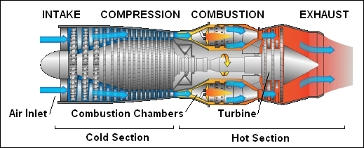 | Figure 1. A 2-D image of a centrifugal type Turbojet Engine [2] |
Each of these components has their respective functions that are required for the running of the engine. These components and their functions have been explained in detail along with the design aspects later.
2. Design of Major Components
Being a mechanical component, a Turbojet Engine had to be designed considering the mechanical aspects like thermodynamics, material properties, machining processes at the design stage. To achieve this, a decent knowledge of the concepts related to the engine was attained through literature survey. The design of the components were made with the help of Ansys Workbench and were visualized using Catia.
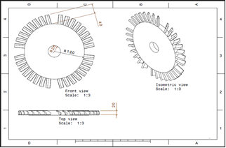
2.1. Design and Fabrication of Impeller
The compressor is driven by the turbine. It rotates at high speed, adding energy to the airflow and at the same time squeezing (compressing) it into a smaller space. During the design following assumptions were made:§ Centrifugal compressor was designed as it is easier and comparatively less expensive to manufacture and provides better efficiency at lower RPM.§ Calculations are done for 8000RPM.§ Inlet angle is 60°.The values like impeller dimensions were obtained by continuous trial and error iterations done using Vista CCD, a tool in Ansys Workbench.
2.1.1. Formulae Used
Ÿ Tangential velocity at inlet,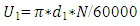 | (1) |
Ÿ Axial velocity at inlet,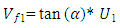 | (2) |
Ÿ Inlet area,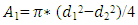 | (3) |
Ÿ Flow area, | (4) |
Ÿ Continuity equation, | (5) |
Ÿ Mass flow rate at outlet, | (6) |
Ÿ Temperature at outlet of compressor | (7) |
Ÿ Enthalpy | (8) |
Ÿ Power required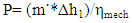 | (9) |
2.1.2. Results of Various Parameters
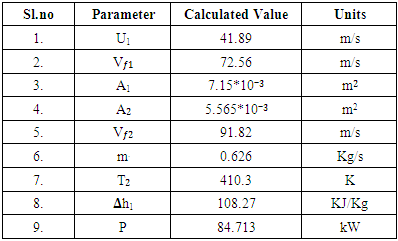
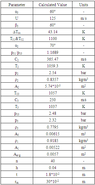
With the above equations [4] the various parameters are like velocity, mass flow, cross section areas, Temperature, enthalpy and power are calculated. These results are used for the sketches and the Ansys work. The results of various parameters are shown in the Table 1. The sketch of the impeller with its 3 views is shown in figure 2.Table 1. Solutions of the various Parameters after calculations
 |
| |
|
 | Figure 2. 2-D drawing of Impeller |
2.1.3. Analysis of Impeller
Pressure at the outlet of impeller was set to 2.9 bar [5]. It is evident from the figure 3, that the pressure developed by each blade is 2.9 bar. This is represented by the green region. The blade produces the pressure required at the outlet, hence the design is satisfactory.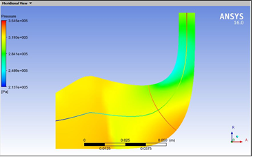 | Figure 3. Pressure at different points on the impeller blade |
2.2. Fabrication of Combustion Chamber
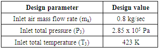
A combustor is a component or area of a gas turbine where combustion takes place. The objective of the combustor in a gas turbine is to add energy to the system to power the turbines, and produce a high velocity gas to exhaust through the nozzle in aircraft applications.The burning of fuel must be complete, otherwise, the engine is wasting the unburnt fuel and creating unwanted emissions of unburnt hydrocarbons, CO and soot. The turbine which the combustor feeds, need high pressure flow to operate efficiently. The flame must be held inside the combustor. If the combustion takes place further back in the engine, the turbine stages can easily be damaged. Space and weight is at a premium in aircraft applications, so a well-designed combustor strives to be compact. There are strict regulations on aircraft emissions of pollutants like carbon dioxide and nitrogen oxides, so combustors need to be designed to minimize those emissions.Table 2. Combustor Inlet Flow Conditions [5]
 |
| |
|
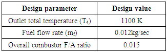
Table 3. Combustor Outlet Flow Conditions [5]
 |
| |
|
In order to match with the required design goals, the combustor primary zone is designed with fuel rich mixture at an equivalence ratio of 0.95. A primary zone airflow rate of 0.1684 kg/sec was found to perform good ignition performance, and promising low NOx emissions and high combustion efficiency at low power conditions with the expenses of increased exhaust smoke and reduced volumetric heat release rate [7]. The distribution of the primary zone air is such that 33.34% i.e.0.027 kg/sec enters through 52 holes of 2.2 mm diameter located in the dome section and the rest 66.6% i.e. 0.0531 kg/sec, flows in the annulus and enters through 102 holes with 2.2 mm diameter each and arranged in two rows of 51 holes each. The remaining airflow is used for both secondary and dilution zones as well as for film cooling of the liner at the outer and inner locations. In the secondary zone, 0.133 kg/sec of air was necessary to achieve an equivalence ratio of 1.7. The total number and size of the secondary zone air injection holes are found 304. Then these holes are in turn in a manner that every set contains 152 holes arranged in two rows of 76 holes of 2.2 mm diameter each.In the dilution zone, an amount of 0.367 kg/sec of air enters through 16 holes of 16 mm diameter each located on the outer liner. In order to protect the liner walls form overheating, it is necessary to introduce an amount of airflow that will form a barrier against the hot following gas. Accordingly, 6.58% of the chamber total airflow rate i.e. 0.053 kg/sec enters in the annular space between the inner liner and engine shaft to film cool the liner wall at this location and distributed through 96 holes total of 2.3 mm in diameter each. These holes are in turn arranged in two sets of 48 holes each that each set in turn contain two rows of 24 holes. This arrangement assures the proper air distribution and guaranties maximum protection to the inner liner wall.An amount of airflow rate is required to enter the annulus passage of the combustor to film cool the outer liner at this location and 9.53% of the chamber total airflow rate i.e. 0.079 kg/sec is admitted through 152 holes total with 2.2 mm diameter each. And in order to distribute this air properly to perform the required task of the liner wall protection from overheating, these holes are in turn arranged in two rows of 76 holes of 2.2 mm diameter each. 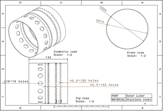 | Figure 4. 2-D drawing of combustion chamber outer liner |
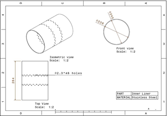 | Figure 5. 2-D drawing of combustion chamber inner liner |
The calculation of the combustion zone length is based on the chamber volume, inlet velocity and combustion products residence time. The combustion chamber volume is in turn determined on the basis of the stirred reactor model [7, 9]. The primary zone products residence time is found 1.317 ms, while the air velocity at the inlet to this zone is 32.5 m/sec. While, the primary zone length is found 85.6 mm. The secondary zone length is determined by the procedure found in [7] i.e. on the basis of achieving just enough residence time to complete the reaction process and to consume the high levels of primary zone carbon monoxide and unburned fuel before the gas enters the dilution zone. And accordingly, the gas residence time in the secondary zone is found 1.003 ms, while the gas velocity at the inlet to this zone is 36.915 m/sec. Thus the secondary zone length is found to be as 74 mm.
2.3. Design and Fabrication of Turbine
The design process involves consideration of power and efficiency, as well as weight, cost, volume, life, noise etc. The first major step in design is to carry out the thermodynamic design point calculations. These include important factors such as component efficiencies, air bleeds, variable fluid properties and pressure losses. The choice of cycle parameters is strongly affected by the engine size, especially the air mass flow rate. Small engines have small blades, which cannot readily be cooled (the manufacturing complexity and cost would be excessive). Hence the pressure ratio may be restricted to allow the blading to be of the air flow, pressure ratio and Turbine Inlet Temperature (TIT) are known, and attention can be turned to the aerodynamic design of the turbo machine, to determine annulus dimensions, rotational speeds and number of stages. In this work, the detailed aero thermal design of a multi-stage axial flow turbine with air cooling is presented, with consideration of the particulars of blade and nozzle geometry, the limiting conditions on the Mach number, annulus divergence and number of blades.
2.3.1. Formulae Used
Ÿ Tangential speed,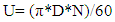 | (10) |
Ÿ Turbine exit blade angle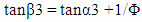 | (11) |
Ÿ Temperature change across the stage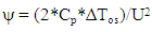 | (12) |
Ÿ Stage reaction | (13) |
Ÿ Turbine inlet flow angle | (14) |
Ÿ Pressure ratio across stage | (15) |
Ÿ Absolute velocity | (16) |
Ÿ Temperature equivalent of kinetic energy | (17) |
Ÿ Pressure at turbine inlet | (18) |
Ÿ Density at turbine inlet | (19) |
Ÿ Area at Turbine inlet | (20) |
Ÿ Temperature at turbine exit | (21) |
Ÿ Density at turbine outlet | (22) |
Ÿ Area at turbine outlet | (23) |
Ÿ Density at nozzle inlet | (24) |
Ÿ Area at nozzle inlet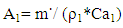 | (25) |
Ÿ Average area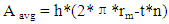 | (26) |
2.3.2. Results
With the above equations [4] the various parameters are like velocity, speed, blade angles, mass flow, cross section areas, Temperature, enthalpy, density, power etc are calculated. These results are used for the sketches and the ansys work. The results of various parameters are shown in the Table 4. The sketch of the Stator and the Rotor are shown in figure 5 and figure 6.Table 4. Values of various Parameters for Turbine
 |
| |
|
 | Figure 6. 2-D drawing of Stator |
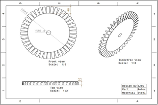 | Figure 7. 2-D drawing of Rotor |
2.4. Design of Nozzle
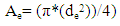
A nozzle is a device designed to control the direction or characteristics of a fluid flow. In a turbojet engine the main function of a nozzle is to increase the outlet velocity of the exhaust gases so as to achieve maximum output thrust which is dependent on output characteristics of the exhaust gases. A convergent nozzle has been designed considering that there shall be no surging or reverse flow of gases and the critical area was calculated using equation (27);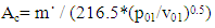 | (27) |
At critical area the velocity of the fluid will be sonic and are lower than that will lead it to supersonic speed and needs divergent section but if the exit are is higher than that of critical area divergent section is not needed and there will not be any choking. Considering, | (28) |
 | (29) |
2.4.1. Data and Solutions
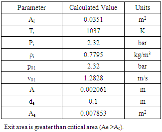
With the above equations [4] the various parameters are like velocity, mass flow, cross section areas, Temperature, density, power are calculated. The results of various parameters are shown in the Table 5. Table 5. Solutions to various Parameters for Nozzle
 |
| |
|
3. Fabrication
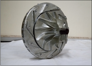 | Figure 8. Assembly of Impeller and diffuser |
 | Figure 9. Assembly of Stator, Rotar and the shaft |
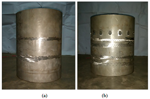 | Figure 10. a) Inner liner of combustion chamber, b) Outer liner of combustion chamber |
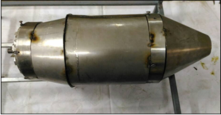 | Figure 11. Turbojet engine complete assembly |
Components of a jet engine need to be fabricated with precision as they are subjected to very high rotational speed, pressure, temperature and fatigue loads which induce high stresses on the components. The major components i.e Impeller, Diffuser, Stator and Rotor were CNC machined and other components i.e combustion chamber inner and outer liner, inner and outer casing, shaft and shaft tunnel, compressor and turbine casing and nozzle we fabricated by the team.
4. Conclusions
The turbojet engine was designed using Catia and Ansys software. The calculations for the design were based on various journal papers and text books. As per the requirement of the combustion chamber the impeller was designed for producing 2.9bar pressure at 8000rpm. The dimensions of the impeller and number of blades were attained by conducting trial and error iterations using Vista CCD on Ansys workbench. Analysis of the flow through the Impeller was done on ansys workbench to validate the Impeller design. Combustion chamber outer liner diameter and inner liner diameter was set to 320mm and 240mm respectively. The overall length of the combustion chamber obtained was 284mm. The position of primary, secondary, dilution holes were such that desirable air flow characteristics were obtained.Based on the calculation the number of stages required to run the compressor and accessories were reduced to one. Height of the blade was 4 cm, inlet angle 60° and outlet angle was set to 70°. The turbine has the aspect ratio of 2 and reaction of 0.4974. The turbojet engine was then fabricated based on the design and assembled.
ACKNOWLEDGEMENTS
The authors of the paper are grateful to Mr. Laxmi Narayan, Proprietor, Super Industries, Yeyyadi who has providing manufacturing support. The team also wishes to acknowledge the support provided by the technical staffs of Mechanical Engineering Department of St Joseph Engineering college.
References
| [1] | Thomas R Yechout, ‘Introduction to aircraft flight Mechanics’, Reston, VA, American Institute of Aeronautics and Astronautics, 2003. |
| [2] | Arthur H. Lefebvre, ‘Gas Turbine Combustion’, Hemisphere Publishing, USA 1983. |
| [3] | Dennis G, ‘Principles of Turbo machinery’, McMillan (1956). ISBN 0-471-85546-4. LCCN 56002849. |
| [4] | Gordon C. Oates, ‘Aero thermodynamics of Aircraft Engine Components’, AIAA education series New York, 1985. |
| [5] | Sumit Kumar, ‘Breaking The Sound Barrier with Air Breathing Jet Engine’, International Journal of Mechanical Engineering and Technology (IJMET) Volume 6, Issue 10, Oct 2015, pp. 154-160, Article ID: IJMET_06_10_017. |
| [6] | Sandeep Kumar Singh, Dr. S.S. Mondal, ‘Redesigning of the combustion chamber for small scale static thrust turbojet engine’, International Journal of Scientific & Engineering Research, Volume 5, Issue 1, January-2014, 934 ISSN 2229-5518. |
| [7] | Abolgasem Mesoad Alarami and Abdulhafid M. Elfaghi, ‘Optimum Design Procedures of Turbojet Combustion Chamber’, 2nd Intl’ Conference on Advances in Engineering Sciences and Applied Mathematics (ICAESAM’2014) May 4-5, 2014. |
| [8] | Nikola Davidović, ‘Mathematical Model of Turbojet Engine Combustion Chamber Primary Zone’, May 2007. |
| [9] | P.P. Walsh & P. Fletcher, ‘Gas Turbine Performance’, Black well Science, England 1998. |

 Abstract
 Reference
 Full-Text PDF
 Full-text HTML