-
Paper Information
- Next Paper
- Paper Submission
-
Journal Information
- About This Journal
- Editorial Board
- Current Issue
- Archive
- Author Guidelines
- Contact Us
Energy and Power
p-ISSN: 2163-159X e-ISSN: 2163-1603
2017; 7(4): 93-98
doi:10.5923/j.ep.20170704.01

Design and Development of Solar-Thermal Energy Storage System of Phase Change Materials
 Abstract
 Reference
 Full-Text PDF
 Full-text HTML
Manjunath H. N.1, Ramesh Babu N.1, Suhas Kumar S.2, Sushanth H. Gowda3, Kiran Aithal S.1
1Department of Mechanical Engineering, NMIT, Bangalore, India
2Technical Lead, Rural Community Lab, Selco Solar Pvt Ltd, Manipal, Udupi, India
3Department of Mechanical Engineering, SJEC, Mangalore, India
Correspondence to: Sushanth H. Gowda, Department of Mechanical Engineering, SJEC, Mangalore, India.
| Email: |  |
Copyright © 2017 Scientific & Academic Publishing. All Rights Reserved.
This work is licensed under the Creative Commons Attribution International License (CC BY).
http://creativecommons.org/licenses/by/4.0/

In this study an attempt has been made to bring out a new kind of organic phase change material (PCM) for energy-storage. The material used is refined BITUMEN of specific grade. In this work the system is fabricated using combination of PCM and water as the storage material. This system consists of two simultaneously functioning heat-absorbing units. One of them is a solar water heater (SWH) and the other thermal energy storage (TES) unit consisting phase changing material packed in spherical capsules. It is found from the literature that use of refined bitumen as phase changing material as better characteristics compared to conventional sensible heat storage system.
Keywords: Phase change material (PCM), BITUMEN, Solar water heater (SWH), Thermal energy storage (TES)
Cite this paper: Manjunath H. N., Ramesh Babu N., Suhas Kumar S., Sushanth H. Gowda, Kiran Aithal S., Design and Development of Solar-Thermal Energy Storage System of Phase Change Materials, Energy and Power, Vol. 7 No. 4, 2017, pp. 93-98. doi: 10.5923/j.ep.20170704.01.
Article Outline
1. Introduction
- The most abundance source of energy to be found on the planet is solar energy. This energy can be stored as thermal energy or electricity, but thermal energy storage is considered the more economical method. Solar thermal energy finds its simplest application in the form of solar water heating, which in itself has enormous potential.In wide spread application of solar energy, heat storage technology, especially latent heat storage technology, are paid attention from a viewpoint of the global environmental problems and the advanced utilization of energy in the world. When considering solar energy as a prospective energy source the development of solar installations, especially solar thermal, has to be accompanied with development of energy storage systems. There are many papers which are a compilation of much of practical information on different PCMs and system developed based on latent heat storage technology. A lot of research work is reported on SHS materials and TES systems in the past and the technology for their utilization is also well developed. In this work the system is fabricated using combination of PCM and water as the storage material.
2. Latent Heat Storage Systems
- Latent heat storage is a relatively new area of study and pioneered by Dr. Telkes in the 1940’s. Although research into latent heat storage for solar heating systems continues, it is increasingly being considered for waste heat recovery and load leveling for power generation. Latent heat storage can be accomplished through solid-liquid, liquid-gas, solid-gas, and solid-solid phase transformations, but the only two of practical interest are the solid-liquid and solid-solid. Temperature-time diagram for the heating of a substance is shown in the Fig.1. It is seen from the graph that the particular solid substance changes its state sequentially from solid to vapour (phase change) with increases in temperature. Solid-solid systems shows much promise, but are only recently being studied. Many phase change materials (PCMs) have been studied for practical use.
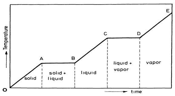 | Figure 1. Temperature–time diagram for the heating of a solid substance |
2.1. Classification of Phase Changing Materials
- There are many materials available which undergo the phase change during heating process and hence useful in solar thermal storage systems. The general classification of latent heat materials or phase changing materials (PCMs) is shown in the Fig.1. Phase change may be in the following form: solid – solid, solid – liquid, solid – gas, liquid – gas. These forms are explained earlier in section 3.2. Organic materials are further described as paraffin and non-paraffin. Paraffin’s qualify as heat of fusion storage materials due to their availability in large temperature range and their reasonably high heat of fusion. Due to cost consideration, only technical grade paraffin’s may be used as PCMs in latent heat stores. Paraffin’s like other mineral oil products are complicated mixtures of several organic compounds and contain one major component called alkanes. The normal paraffin’s of type CnH2n+2 are a family of saturated hydrocarbons with very similar properties. Paraffin wax consists of a mixture of mostly straight chain nalkanesCH3–(CH2)–CH3. The crystallization of the (CH3) -chain release a large amount of latent heat. Both the melting point and latent heat of fusion increase with chain length. Paraffin's between C5 and C15 are liquids, and the rest are waxy solids. Paraffin wax is the mainly used commercial organic heat storage PCM. Non-paraffin’s (Fatty acids): The non-paraffin organics are the most numerous of the phase change materials with highly varied properties. Each of these materials will have its own properties unlike the paraffin’s, which have very similar properties. This is the largest category of candidate’s materials for phase change storage. These materials are flammable and should not be exposed to excessively high temperature, flames or oxidizing agents. Fatty acids have high heat of fusion values comparable to that of paraffin’s. Fatty acids also show reproducible melting and freezing behavior and freeze with no super cooling. Fatty acids, characterized by the chemical formula CH3(CH2)2nCOOH, have much the same characteristics as paraffin’s. Inorganic phase change materials are further classified as salt hydrate, metallics and clathrates. These phase change materials do not super cool appreciably and their heats of fusion do not degrade with cycling. Salt hydrates: are some of the oldest and the most important group of PCMs, which have been extensively studied for their use in latent heat thermal energy storage systems. They consist of a salt and water, which combine in a crystalline matrix when the material solidifies. Eutectics have a minimum melting composition of two or more components, each of which melt and freeze congruently. Eutectic nearly always melts and freezes without segregation since they freeze to an intimate mixture of crystals, leaving little opportunity for the components to separate. On melting both components liquefy simultaneously, again with separation unlikely. Some segregation PCM compositions have sometimes been incorrectly called eutectics, since they are minimum melting. Because of the components undergoes a peritectic reaction during phase transition, however, they should more properly be termed peritectics.
2.2. Bitumen as Phase Changing Material
- Bitumen is the oldest known engineering material and has been used from the earliest times. Bitumen is a non-crystalline highly viscous material, black or dark brown, sticky which is substantially soluble in carbon disulphide (CS2), possessing adhesive, water-proofing qualities and composed primarily of highly condensed polycyclic aromatic hydrocarbons. Bitumen is a mixture of organic liquids and has complex mixture of a large number of high molecular weight organic compounds made by processing of petroleum crude oils. At ambient temperatures bitumen is a stable, semi-solid substance. Molecular weight wise, bitumen is a mixture of about 300 - 2000 chemical components, with an average of around 500 - 700. Elementally, it is around 95% carbon and hydrogen (± 87% carbon and ± 8% hydrogen), and up to 5% sulfur, 1% nitrogen, 1% oxygen and 2000ppm metals. Bitumen's are composed mainly of highly condensed polycyclic aromatic hydrocarbons. The classification of petroleum bitumen produced by the refining and manufacturing process is shown in Fig.2. Cutback bitumen's consist basically of bitumen that has been diluted in order to make it more fluid for application, mainly in road making. Their fluidity depends on the degree of hardness of the bitumen base and the proportion of diluents (or flux) to bitumen. They are classified according to the time it takes them to become solid, as rapid curing (RC), medium curing (MC) or slow curing (SC) cutbacks. The cutback varies according to the flux, white spirit commonly being used for RC grades, kerosene for MC and diesel for SC. They set as the flux evaporates. This evaporation is currently regarded as a potentially undesirable characteristic from the point of view of the environment and health and safety, so cutback bitumen's are looked upon less favorably than the more modem bitumen emulsions.
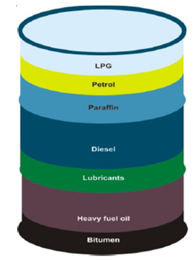 | Figure 2. Fractional Distillation |
|
2.3. Laboratory Investigation: Determination of Thermo-Physical Properties
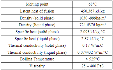
- Scientists and engineers agree that modeling and simulation cannot stand alone and provide response about thermodynamic behaviors and phase diagrams without the help of good experimental data. The samples for laboratory tests were provided by Mangalore Refinery and Petrochemicals Limited (MRPL) a subsidiary of ONGC. Thermal properties of Bitumen are shown in Table 1. It is found that Bitumen melts at 68°C from this curve. Bitumen is a not a single element like ice, thus it melts non-congruently. Thermal conductivity data is of prime importance in designing thermal storage system. Specific heat and heat conductivity (thermal conductivity) of bitumen at solid was known from literature survey and at liquid phase the thermal conductivity was measured by hot-wire instrument (HPCL Laboratories). Specific heat of bitumen at liquid state was measured by simple laboratory tests using Boyle’s gas calorimeter without heat insulation to the vessel To find latent heat of enthalpy many experiment trials were conducted and percentage error was evaluated it was found that bitumen has huge latent heat of fusion around 450.367KJ/Kg.Photographic views of laboratory testing are shown .Bitumen originally exists in nature and is extremely safe material used as binder for road construction. Corrosiveness to container material was evaluated. Bitumen sample was heated above 100°C and it was that bitumen flows like water at 131°C with coefficient of cubical expansion about 0.0006/°C. Other Kinetic and Chemical investigations was studied and related experiments were conducted and observed manually (HPCL Laboratories).
3. Design Concepts
- There is a need for the storage of solar energy which cannot be avoided. The question arises as to how thermal energy storage system can successfully be fabricated and implemented in service system of the built environment to utilize optimum energy. The first requirement of the storage system is that it must be appropriately sized and requirement is fulfilled by following an approximate thumb rule for fixing the size of shell by calculating the mass of PCM to be stored in the shell. Hence mass of PCM to be stored and the porosity (void fraction) is the major criteria during the fabrication process of shell. The second requirement of the storage system is that to use best suited materials for the fabrication of whole system. The geometric factors that have been taken into account during the current research are the diameter, length, thickness of the cylindrical specimen, porosity (void fraction),type of material used to store phase changing material, its size. The shell is suitably insulated with rock wool (mineral wool). In this system a TES unit is designed, constructed and integrated with solar collector. The design concepts are explained in this chapter.
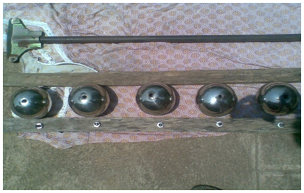
4. Experimental Setup
- The experiment test rig is shown in figure.3, (1) solar flat plate collector (varying heat source); (2) Water pump ; (3) Flow Control Ball Valves; (4) Hot Water Flow Meter; (5) TES Shell; (6) PCM Modules; (7) 12 Channel Temperature Indicator; Tp and Tf - temperature sensors (K- type thermocouples). The thermocouples are placed at five layers (segments) of the TES shell that is at x/L = 0.20, 0.40, 0.60, 0.80, 1.0 Easily maneuverable (adds mechanical stability to a system). The total volume capacity of the PCM modules is 30.18 litres (100%), but filled with just 28.0857 liters (93% of PCM volume) and the remaining volume of 53.45 liters is occupied by HTF (water) in the storage shell. The refined bitumen used as PCM has a melting temperature of 68°C and water is used as both SHS material and HTF (Water is used as HTF as the system corresponds to that one used For solar water heater). All thermocouples are connected to twelve channels K-type temperature indicator connected to enable the recording of the temperature readings (provides instantaneous digital Outputs) during various test scenarios. Multi meters having provision to measure temperature directly as well as thermometer were also used to cross check the temperature. The temperature readings were continuously recorded for every 5 minute interval and also solar irradiance was monitored on system for every 10 minute intervals with the help of calibrated KDS-051 Global Radiation Sensor Depending on the experiment requirements.
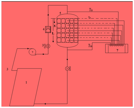 | Figure 3. Experiment test rig |
4.1. Procedure
- The research work is carried out in two phases: Storage performance with closed-loop solar system (Charging) and Storage performance with open-loop solar system (Discharging). Experiments were conducted for both natural as well as forced circulation. Ambient temperature water as well as cold water (15°C) was used to analyze recovery effect and the storage performance of the PCM under open-loop operation patterns, structured to simulate daily use patterns. Open loop (Discharging) trials were carried out by both continuous and batch wise processes.
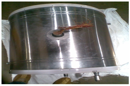 | Figure 4. Solar Tank |
 | Figure 5. Solar Tank |
4.1.1. Closed-loop Operation of Solar Thermal System (Charging Process)
- In the SHS system during the closed-circuit operation, the TES shell is integrated with 2 m2 active solar flat plate collector (varying inlet heat source). The key experimental parameters are HTF inlet temperature and its flow rate. Experiments are conducted at varying HTF inlet temperatures (HTF inlet temperature varies in accordance with the solar insulation) and various flow rates of 2, 4 and 6 l/min during charging process. Temperatures of water in the storage shell and HTF are recorded at intervals of 10 minutes. In the case of LHS system, the TES shell is integrated with an active solar flat plate collector of 2m2 area (varying inlet heat source) with the PCM modules (capsules) in the TES tank being immersed in water. The key experimental parameters are HTF inlet temperature and its flow rate with fixed porosity (void fraction) of 62%. Experiments are conducted at varying HTF inlet temperatures (and the HTF inlet temperature varies in accordance with the solar insulation) and various flow rates of 2, 4 and 6 l/min during charging process. In this case, PCM modules in the TES tank are surrounded by water. No water was discharged from the system through the outlet line during closed loop operation. During the charging process (storing of heat energy) the HTF is circulated through the TES tank continuously. Initially the energy is stored inside the capsules as sensible heat until the PCM reaches its melting temperature. As the charging process proceeds, energy storage (latent heat) is achieved as the refined bitumen melts at a constant temperature (68 1°C). Finally, after complete melting of PCM is achieved, further heat addition from the HTF causes the PCM to heat higher above the melting point, thereby again storing heat sensibly in liquid PCM. Thus the PCM becomes superheated. Temperatures of the PCM and HTF at different locations of the TES shell are recorded at an interval of 10 minutes. The charging process is continued until the thermal equilibrium is attained between HTF and PCM temperatures. The charging process was continued until the PCM temperature Tp attained maximum temperature. Most of the time closed-loop operation was carried out up to 4pm during the daytime (few times closed loop operation was also stopped after 3pm due to over cast conditions). For both active and passive circulation the PCM was charged throughout the day, whenever the user does not demand hot water during the daytime.
4.1.2. Open-loop Operation of Solar Thermal System (Discharging Process)
- In this experiment, the solar water heater (SWH) is separated from the thermal energy storage (TES) system by closing the appropriate operating valves. The Open-loop operation (the energy retrieval) experiments are carried out in two methods to make the best use of maximum thermal energy that is preserved in the storage shell. In the first method referred to as a non- discrete (continuous process), the cold water at an ambient temperature ranging from 32 to 36°C (differs day to day since overhead black sintex tank absorbs heat from the sun) is circulated continuously through the TES shell to recover the stored heat energy. In this pilot model the water was withdrawn from the system through the top of the storage shell was directly compensated by water from the main water supply at the bottom automatically. In the second method referred to as a discrete process (non-continuous time), a certain quantity of hot water is withdrawn from TES shell and mixed with cold water at 32°C to get the required amount of hot water for the domestic purpose at an desired average temperature for direct use by an any individual. And the shell is again filled with cold water of quantity equal to the amount of water withdrawn. Again after a time interval of 10 min allowing transfer of energy from PCM another batch of hot water is withdrawn and mixed with cold water to get adequate amount of hot water for individual purpose. The cold freezer water (15°C) was used to analyze recovery effect and the storage performance of the PCM under open-loop operation patterns, structured to simulate daily use patterns (in case of winter season) and process was discrete (non-continuous time). This process is continued until the PCM temperature comes to ambient water temperature. Optimum use of energy is retrieved by removing all the thermal energy at the end of the day.
5. Results and Discussion
- The objective of this work is to establish benefits associated with the use of refined bitumen as energy storage media. The solar heater unit was designed and fabricated and then related experiments were carried out. In this chapter a detail analysis of the results obtained from the various experiments and complete discussions has been made.
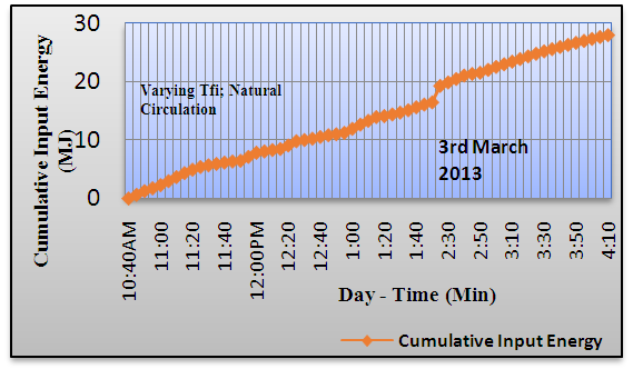 | Figure 6. Variation in Cumulative Input Energy |
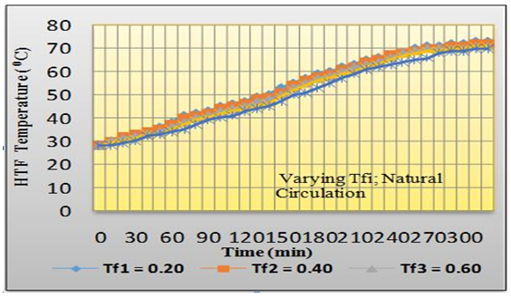 | Figure 7. Temperature-time variations of HTF in the TES shell for passive (natural) circulation |
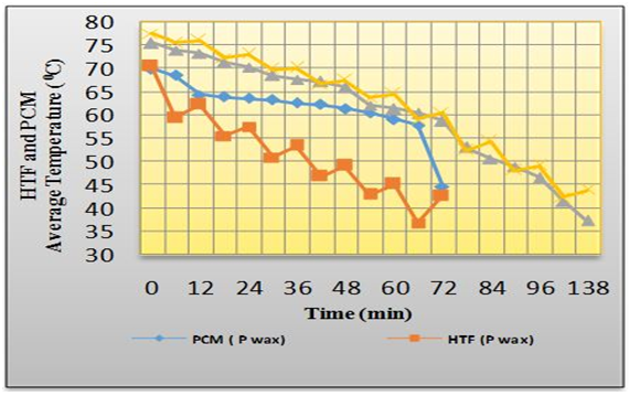 | Figure 8. Comparison of variations of HTF and PCM average temperature with open loop investigation during discrete (non-continuous time or batch wise) discharging process. Using bitumen and paraffin wax as PCMs |
6. Conclusions
- Based on the results and discussions carried out in the previous chapter the following conclusions can be drawn:1. Bitumen can be used as solar thermal storage medium along with water with good results (better performance) that is higher temperature can be achieved in solar heater unit using refined bitumen of low softening point as phase change material (PCM).2. As the flow rate increases the reduction in charging time for the PCM (refined bitumen) to achieve its melting point or phase change reduces. Thus the charging time is decreased by 3.57%, 10.7% and 17.8% when the flow rate is increased from NC to 2 l/min, 2 to 4 l/min and 4 to 6 l/min with at an average charging rates of 1.190, 1.234, 1.333 and 1.666 kW respectively. Since the heat transfer rate possible from the HTF to the PCM in the storage shell is higher than the heat-receiving rate of HTF from the solar flat plate collector. Hence, it is possible to reduce the charging time further by increasing the solar collector surface area.3. The configuration of having combination of forced (active) and natural (passive) circulation for a closed loop operation has better results when compared to single configuration charging.
ACKNOWLEDGEMENTS
- The authors acknowledge SELCO SOLAR INDIA Pvt Ltd. providing the support and infrastructure to carry out our research.