Sheetal Narayan Shetty, Prashanth Kamath
Department of Mechanical Engineering, Canara Engineering College, Mangalore, India
Correspondence to: Sheetal Narayan Shetty, Department of Mechanical Engineering, Canara Engineering College, Mangalore, India.
| Email: |  |
Copyright © 2017 Scientific & Academic Publishing. All Rights Reserved.
This work is licensed under the Creative Commons Attribution International License (CC BY).
http://creativecommons.org/licenses/by/4.0/

Abstract
A large increase in the requirement of energy is the biggest problem faced by the world at present. This has resulted in usage of more and more energy resources which is not a good sign. So there should be actions taken so as to reduce the energy losses from any system and an attempt should be made to utilize maximum amount of the energy supplied by an energy consuming system. Keeping these things in mind a water cooled condenser refrigerator system is developed. In this paper the COP of the refrigerator by using water as the cooling medium instead of air for condenser system is calculated, which is the cooling medium in conventional refrigeration system otherwise. Here comparison is made between the COP of air and water cooled condenser refrigeration system to find the percentage increase in COP. By this it is possible to utilise more part of the energy supplied to the refrigeration system.
Keywords:
Water cooled condenser, Temperature, COP, System
Cite this paper: Sheetal Narayan Shetty, Prashanth Kamath, Performance Assessment of Water Cooled Condenser Refrigeration System, Energy and Power, Vol. 7 No. 3, 2017, pp. 70-74. doi: 10.5923/j.ep.20170703.03.
1. Introduction
Refrigerator is a device which extracts heat continuously from the system and dissipate that heat into the surroundings with the help of an external aid like electrically driven compressor which is described in second law of thermodynamics. There are many statements for second law of thermodynamics, but two of them are very important they are, i) Kelvin and Planck Statement- “No (heat) engine whose working fluid undergoes a cycle can absorb heat from a single reservoir, deliver an equivalent amount of work, and deliver no other effect.” and ii) Clausius Statement- “No machine whose working fluid undergoes a cycle can absorb heat from one system, reject heat to another system and produce no other effect.” The term “Refrigeration” is defined as a process of removing heat from a substance and maintaining its temperature well below the atmospheric temperature under controlled conditions [1]. Refrigeration has been adopted from ancient times where they had used method of artificial cooling in ice making; nowadays they are used for preservation of the perishables such as milk, food, drinks, medicines, etc. and indoor air cooling to provide human comfort and cool environment is required in electronic, precision manufacturing and process industries, and also in various other applications like cryogenics, etc. [2]. The application of refrigeration is in plenty of numbers but one of the most important applications of refrigeration has been the preservation of perishable food products by storing them at lower temperature [3]. In conventional Refrigeration System the condenser is cooled by air which can be free convection or in some cases by forced convection where a forced draught fan forces the air over the condenser [4]. But the COP of such a system is relatively low since heat carrying capacity of air is less [5]. The COP can be increased by using water as a cooling medium because water has more heat carrying capacity than air. In this experiment the air cooled condenser of a domestic refrigerator has been replaced by a water cooled condenser.
2. Methodology
As most of the refrigeration system are working on vapour compression system with four basic components they are evaporator, compressor, condenser and expansion device. In a refrigerator, a medium called refrigerant continuously extract the heat from the space within the refrigerator (refrigerated space) which is to be kept cool at temperature less than that of the atmosphere and finally rejects this heat to surrounding air. Some of the fluids like, Ammonia, Freon, Methyl Chloride, Carbon dioxide are the commonly used refrigerants. Here we are using R134a fluid as our refrigerant. As we cannot change or upgrade evaporator, compressor and expansion device easily since it is internally fabricated so we have chosen to increase the efficiency of the refrigerator by increasing the heat transfer rate through the condenser unit.In this experiment the condenser unit is changed from air cooled condenser of 9m length of iron material to water cooled condenser of 3m length of copper material. To cool the condenser coil, the condenser is enclosed in a small tank of dimension 0.45m×0.325m×0.025m. Thus the capacity of the tank is approximately 3.6×10⁻³m3 or 3.6 litres. This design is so chosen to enclose the condenser for water cooling. Pipes are provided on the top face and lower face at suitable positions to circulate water to and from the upper tank. The tank of size approximately ten times the lower tank is placed on the top of the refrigerator which serves as a heater box. In order to measure the performance of the refrigerator two pressure gauges have been installed one at the suction and another at the delivery of the compressor. The range of delivery pressure gauge is 500psi and that of suction is 150psi. For measuring temperatures at different points thermocouples have been installed. There are six thermocouples placed at different positions to measure various temperatures.
3. Method
The lower temperature refrigerant in the liquid state enters the evaporator and vaporise by absorbing the heat from the evaporation chamber. Then the refrigerant is compressed to a higher temperature and high pressure by a compressor. The vapour refrigerant is then condensed in the water cooled condenser to lower temperature and high pressure. The refrigerant gives away its latent heat in condenser and get condensed. This heat is taken away by the water in the smaller tank surrounding the condenser. The temperature of the water in the condenser tank gets increased and its density decreases. Due to the thermo syphon action, the hot water rises up and reaches the upper tank. Simultaneously cold water enters to the lower tank from the lower side of the upper tank, thus maintaining a moderate temperature in the lower tank. The condensed refrigerant then enters the capillary expansion and expands to a lower temperature and low pressure. Then again the low temperature low pressure refrigerant enters the evaporator and the cycle repeats. In the water cooled condenser the vapours of the refrigerant gives off its latent heat to the water through the copper tubes and consequently condenses into liquid so that it can be recirculated in the refrigeration cycle. The latent heat of the refrigerant that is given off in the condenser comprises mainly of the heat absorbed from the refrigerated space and the heat developed due to compression of the refrigerant. Operation of a water cooled refrigeration is as shown in the Figure 1.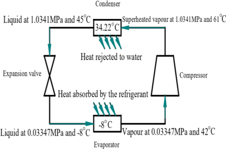 | Figure 1. Refrigeration cycle in water cooled condenser refrigeration system |
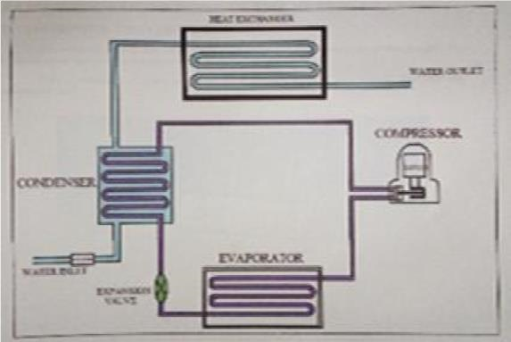
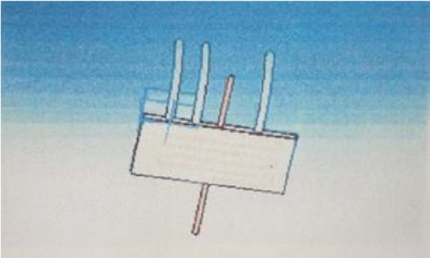
In this experiment a domestic refrigerator was purchased and necessary modifications were done to obtain the required outcome. The capacity of the refrigerator is 165 litres and the refrigerant used is R134a. The condenser of reduced length is enclosed in a tank (lower tank) which is as shown in Figure 2 and Figure 3. The tank is filled with water which acts as a cooling medium. In order to circulate the heated water, no separate pump is used, which would require extra power. Hence to facilitate circulation of water, thermo syphon principle is used. For this purpose water from tank placed above the refrigerator is made use of. A heater box is also made through which the hot water circulation from the condenser tank passes as shown in the Figure 4 and Figure 5. The upper end of the lower tank is connected to the upper end of the upper tank and the lower end of the lower tank is connected to the water supply tank. The lower end of the upper tank is let out free for the water to exit the system after the circulation as shown in Figure 3. To measure and compare the performance of this refrigerator with the conventional refrigerator, two pressure gauges have been installed in the refrigerator. The remaining components of the refrigerator are not altered.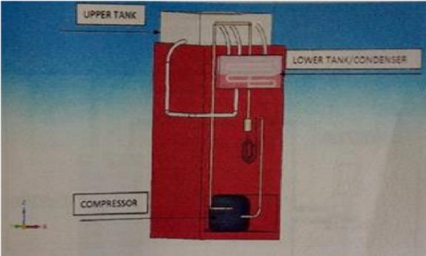 | Figure 2. Isometric view of a water cooled domestic refrigerator |
 | Figure 3. Line diagram of water cooled refrigerator |
 | Figure 4. Water cooled condenser lower tank |
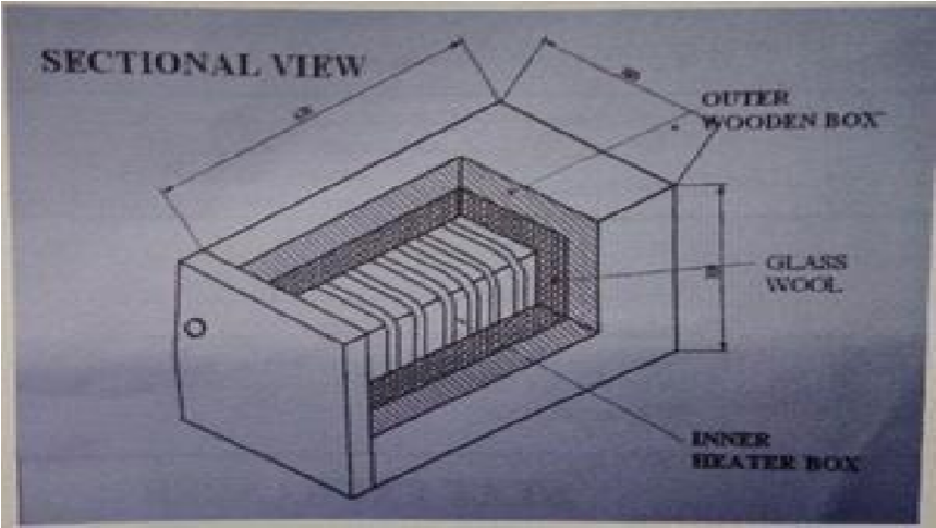 | Figure 5. Sectional view of heater box |
4. Calculation
The Table 1. shown below gives the amount of heat rejected in air and water cooled condenser and for different lengths.Table 1. Heat rejected in air and water cooled condenser for different lengths of condenser
 |
| |
|
The Table 2. shows the comparison of time for the evaporator temperature drop between air cooled and water cooled condenser refrigerator.Table 2. Time comparison table for evaporation temperature drop between air cooled and water cooled condenser refrigerator
 |
| |
|
Terms used are as follows:T1 = temperature before compression (°C)T2 = temperature after compression (°C)T3 = temperature after condensation (°C)T4 = temperature after expansion (°C)T5 = temperature of water in heater box (°C)T6 = temperature inside freezer (°C)h1 = enthalpy before compression (kJ/kg)h2 = enthalpy after compression (kJ/kg)h3 = enthalpy after condensation (kJ/kg)h4 = enthalpy after expansion (kJ/kg)P1 = pressure before compression (MPa)P2 = pressure after compression (MPa)Calculation of COP for air cooled condenser refrigerator:Observation:Refrigerant – R134aCapacity = 165 litresRating = 230V, 50Hz, 1.1AmpsRoom temperature = 32°CEnthalpy values for corresponding pressure and temperature from R134a pressure-enthalpy chart are,h1(P1,T1) = (0.055,35.6) = 425kJ/kgh2(P2,T2) = (1.27,70) = 450kJ/kgh3(P3,T3) = (1.27,49) = 270kJ/kg = h4 | (1) |
 COPair = 6.28Calculation of COP for water cooled condenser refrigerator:Observation:Room temperature = 30°CEnthalpy values for corresponding pressure and temperature from R134a pressure-enthalpy chart are,h1(P1,T1) = (0.033447,46) = 440kJ/kgh2(P2,T2) = (1.0341,55) = 460kJ/kgh3(P3,T3) = (1.0341,45) = 250kJ/kg = h4
 | (2) |
 COPwater = 9.5Percentage increase in COP:
 | (3) |
 %increase = 51.27%
5. Results and Discussions
Ÿ COP of air cooled refrigerator is 6.28 and the COP obtained for water cooled condenser is 9.5. Thus COP is increased by 51.27%.Ÿ Thermo syphon action has been observed.Ÿ Time for cooling in the evaporator has been reduced which is shown in Figure 6.Ÿ The condenser outlet temperature is reduced drastically which is shown in Figure 7.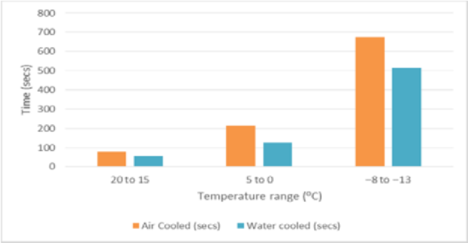 | Figure 6. Graph of temperature v/s time of evaporator for air and water cooled refrigerator |
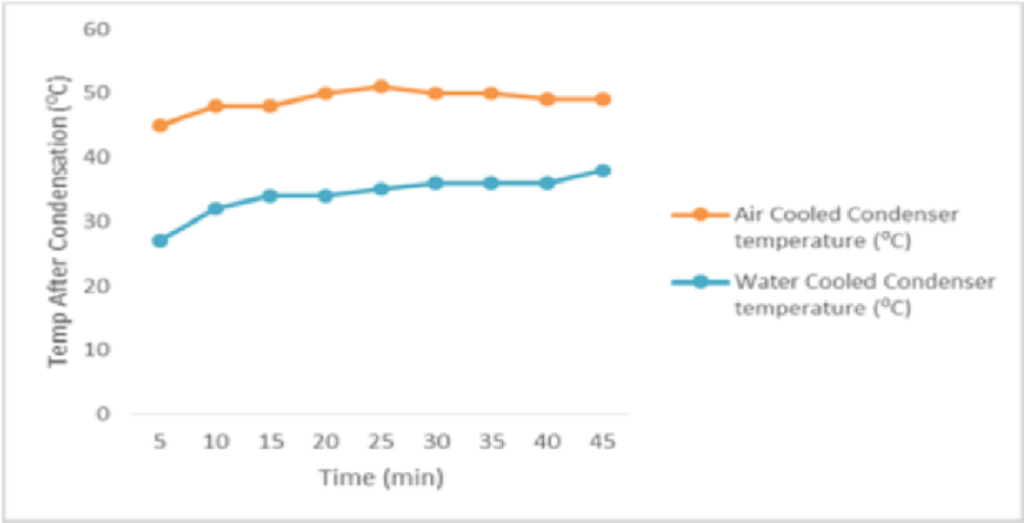 | Figure 7. Graph of time for water and air cooled refrigerator v/s temperature after condensation |
6. Advantages and Disadvantages
Advantages:Ÿ Since water cooling is more efficient than air cooling, time required for cooling is less and hence, COP is increased.Ÿ Length of the condenser pipe is reduced which reduces the compressor work and hence increases its efficiency.Ÿ Water cooling system does not require any external power.Disadvantages:Ÿ Use of water as a cooling medium might cause corrosion problem. Ÿ Presence of water tank makes the system bulky and this might cause problem during domestic use.Ÿ Use of water as a cooling medium may result in the formation of scales in the supply line.
7. Scope for Future Work
Ÿ Appropriate coolant must be used in place of water to prevent corrosion problems.Ÿ Suitable alterations can be made in the design, so that the system can be easily moved.
8. Conclusions
Ÿ With the incorporation of water cooled Condenser, the Refrigeration Effect increases which in turn increases the COP.Ÿ Time for cooling in the Freezer is reduced drastically. Hence, time required to reach the required temperature is less and the compressor can shut off quickly saving electrical power.Ÿ Reduced condenser length results in lesser refrigerant travel distance and hence the pumping power required is less.Ÿ With the incorporation of water cooled Condenser, the net weight of the system increases.Ÿ Since the specific heat of water is 4.187kJ/kg/°C which is higher than any other common substance and because air is having its specific heat as 1.005kJ/kg/°C which is lower than water, hence the heat carrying capacity by water is more than air which leads to lower condenser temperature in water cooled condenser than that of air cooled condenser.Ÿ With the incorporation of water cooled condenser, on an average we can have 14.7°C less condenser temperature than that of air cooled condenser.Ÿ Since Copper tube (k=386W/mK) is having higher Thermal Conductivity than that of Iron tube (k=72.7W/mK), heat transfer is more in copper tube.Ÿ The amount of heat transfer rate in copper tube condenser of 3m is 4.5 times more than that of the iron tube condenser of 9m.Ÿ Since the distance between the centre of upper tank and lower tank is 0.5m which is less than 12m (limit up to which thermo syphon principle for water is applicable), thermo syphon principle is observed.Ÿ The time taken for water cooled condenser is 27.27% lesser than that of air cooled condenser from 20°C to 15°C, 41.31% lesser from 5°C to 0°C and 23.48% lesser from -8°C to -13°C respectively.
References
| [1] | Khurmi R.S., and Gupta J.K., Refrigeration and Air Conditioning, S Chand, 2012. |
| [2] | Hundy G.F., Trott A.R., and Welch T.C., Refrigeration and Air Conditioning, 4th Edition, Butterworth-Heinemann, 2008. |
| [3] | Admiraal D. M., and Bullard C. W., Heat Transfer in Refrigerator Conditioners and Evaporators, University of Illinois, 1993. |
| [4] | Holman J.P., Heat Transfer, Mc Graw Hill, 2003. |
| [5] | Domkundwa and Arora, Refrigeration and Air Conditioning, Dhanpat Rai and Sons, 1994. |
| [6] | Shan K. W., Handbook of Air Conditioning and Refrigeration, 2nd Edition, Mc Graw Hill, 2003. |


 COPair = 6.28Calculation of COP for water cooled condenser refrigerator:Observation:Room temperature = 30°CEnthalpy values for corresponding pressure and temperature from R134a pressure-enthalpy chart are,h1(P1,T1) = (0.033447,46) = 440kJ/kgh2(P2,T2) = (1.0341,55) = 460kJ/kgh3(P3,T3) = (1.0341,45) = 250kJ/kg = h4
 COPwater = 9.5Percentage increase in COP:
 %increase = 51.27%

 Abstract
 Reference
 Full-Text PDF
 Full-text HTML
