-
Paper Information
- Paper Submission
-
Journal Information
- About This Journal
- Editorial Board
- Current Issue
- Archive
- Author Guidelines
- Contact Us
Energy and Power
p-ISSN: 2163-159X e-ISSN: 2163-1603
2017; 7(2): 50-60
doi:10.5923/j.ep.20170702.03

Computational Investigations on the Possible Turbo-Charging of a V6 Spark Ignition Engine Using Ethanol and Gasoline as Alternative Fuels
 Abstract
 Reference
 Full-Text PDF
 Full-text HTML
M. Marouf Wani
Mechanical Engineering Department, National Institute of Technology, J&K, Srinagar, India
Correspondence to: M. Marouf Wani, Mechanical Engineering Department, National Institute of Technology, J&K, Srinagar, India.
| Email: |  |
Copyright © 2017 Scientific & Academic Publishing. All Rights Reserved.
This work is licensed under the Creative Commons Attribution International License (CC BY).
http://creativecommons.org/licenses/by/4.0/

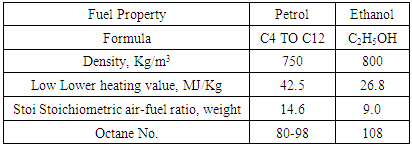
This paper presents the results of computer simulation based thermodynamic analysis on a V6 TCI BI-Turbo spark ignition engine under constant speed and variable load operation using petrol and ethanol as alternative fuels. The results were simulated in the professional thermodynamic simulation software namely AVL BOOST. The purpose of these research investigations is to explore the possibility of using petrol and high octane number rated ethanol for power boosting of a naturally aspirated spark ignition engine using the concept of turbo-charging. The engine was modeled from its basic elements using various mathematical models available for spark ignition engine on combustion, heat transfer, frictional power etc. Conservation laws of mass, momentum and energy using numerical methods were solved for getting the results. The results were computed for the octane number requirement for petrol and ethanol for the turbocharged version of the spark ignition engine. The results were also computed for its performance and emission characteristics. The results show that commercially available ethanol will undergo normal combustion when used as fuel in the turbocharged spark ignition engine. Also ethanol based engine produces less CO and HC emissions. The NOx emissions are lower with ethanol under low load operation and higher under high load operation as compared to petrol. In order to use commercial petrol as a fuel in the turbo-charged spark ignition engine, its octane number needs to be upgraded.
Keywords: Renewable Fuel, Ethanol, Octane Number Requirement, Turbocharged, Multi-cylinder, Spark Ignition Engine, Performance and Emissions
Cite this paper: M. Marouf Wani, Computational Investigations on the Possible Turbo-Charging of a V6 Spark Ignition Engine Using Ethanol and Gasoline as Alternative Fuels, Energy and Power, Vol. 7 No. 2, 2017, pp. 50-60. doi: 10.5923/j.ep.20170702.03.
Article Outline
1. Introduction
- It is a well established fact that petroleum resources are available only in a few countries. The problem gets further multiplied when huge volumes of petroleum are needed to be shipment across the various continents. Day by day the consumption of petroleum is increasing at a faster rate. This together with the possible depletion of the existing petroleum resources, needed for running the internal combustion engines, gives a clear signal for searching a suitable future source of energy for internal combustion engines. The renewable source of energy could be the best possible option as compared to any non renewable source serving the same purpose. Ethanol is one among such renewable sources of energy that is still used only marginally for running the internal combustion engines. Ethanol can be produced in almost all countries from sources like sugarcane, beet root, potato etc.The performance of the existing naturally aspirated spark ignition engines can be improved further by incorporating turbochargers in these engines. However any type of hardware based change or improvement in its technology involved has to be compatible with the physical and chemical properties of the fuels to be used in these engines.The octane number of the commercial petrol puts some constraint for further power boosting and downsizing the existing gasoline engine by the addition of a turbocharger in it. Turbo-charging a naturally aspirated spark ignition engine needs high octane number based petrol. The octane number requirement of the turbocharged spark ignition engines operated with petrol is higher than that of the commercially available petrol. Renewable liquid fuel like ethanol and also the petroleum based gaseous fuel like CNG have high octane numbers and as such are suited for use in the turbocharged spark ignition engines. The use of commercially available petrol having an octane number of 90-98 experiences knock based limitations for turbo-charging a naturally aspirated spark ignition engine. However the commercially available renewable ethanol has an octane number of 108 and as such can be used for investigating the possible turbo-charging a naturally aspirated spark ignition engine for boosting its performance further and also for improving its emission characteristics. Also the octane number requirement of the engine with petrol fuel varies over the full range of speed and load on the engine. This necessitates the need for the design of a “Octane On Demand” type of fuel supply system for the turbocharged spark ignition engines. This basically will involve the supply of a combination of two types of fuels, one having a high octane number and the other having a lower octane number. The fuel supply system will supply a certain mixture of these two fuels as governed by the octane demand of the engine at a particular load and speed. One of the fuels can be the conventional gasoline or petrol and the second fuel can be ethanol having a higher octane rating as compared to petrol. The combination of these two fuels will allow the use of turbochargers for further downsizing and power boosting of the existing spark ignition engines run by petrol.
2. Literature Survey
- John B. Heywood in the various chapters of his text book writes that most modern turbocharged engines use port fuel injection. This provides easier electronic control of fuel flow and improves the dynamic response of the system by reducing fuel transport delays. The bmep of most production spark-ignition engines at wide-open throttle is knock-limited over part of the engine speed range. The compression ratio (8-12) is usually set at a sufficiently high value so that some spark retard from MBT timing is needed to avoid knock for the expected range of available fuel octane rating and sensitivity. If the end of combustion process is progressively delayed by retarding the spark timing, the peak cylinder pressure occurs later in the expansion stroke and is reduced in magnitude. Attempts to boost the output of a given size spark ignition engine by an inlet air compression device that increases air pressure and temperature will aggravate the knock problem, since the end gas pressure and temperature will increase. However the higher output for a given displacement volume will decrease engine specific weight and volume. Also for the same maximum power, the smaller turbocharged engine should offer better fuel economy at part load. At a given part-load torque requirement, the mechanical efficiency (lower frictional loss) of the smaller turbocharged engine is higher. The variables that are adjusted to control knock in turbocharged SI engine are: compression ratio, spark retard from optimum, charge air temperature (inter-cooling), and fuel-air equivalence ratio. Most turbocharged SI engines now use a knock sensor and ignition-timing control system so that timing can be adjusted continuously to avoid knock without unnecessary retard. With a knock sensor, sensing above-normal vibration levels on the cylinder head, ignition timing can be automatically adjusted in response to changes in fuel octane rating and sensitivity, and ambient conditions. The occurrence of knock at high speeds corresponding to WOT for such engines is avoided by reducing the exhaust flow through the turbine as speed increases by bypassing a substantial fraction of the exhaust around the turbine through the wastegate or flow control valve. Turbo-charging the naturally aspirated 2.3-dm3 engine results in a 36 percent increase in maximum engine torque under certain conditions. In a vehicle context, the low-speed part-load advantage of the smaller size but equal power turbocharged engine should result in an average fuel economy benefit relative to the larger naturally aspirated engine. Knock is a phenomenon that is governed by both engine and fuel factors; its presence or absence in an engine depends on the antiknock quality of the fuel. Individual hydrocarbon compounds vary enormously in their ability to resist knock, depending on their molecular size and structure. Practical fuels are blends of a large number of individual hydrocarbon compounds. The octane number requirement of an engine or vehicle or vehicle-engine combination is defined as the maximum fuel octane number that will resist knock throughout the engine’s operating speed and load range. [1]Bourhis etal in his paper describes the research investigations on the effect of properties of the fuels used and engine injection configuration effects on the octane on demand concept for a dual fuel turbocharged spark ignition engine.The methodology used involved using a dual fuel injection strategy, involving a low-RON base fuel and a high-RON octane booster. Both GDI and PFI concepts were tried on the above mentioned multi-cylinder engine for these investigations. The percentage by volume of two fuels on each injector was regulated to fit the RON requirement function of engine operating conditions. To find the best fuel combination a very low-RON naphtha-based fuel (RON 71) and a non-oxygenated gasoline (RON 91) were used as base fuels. The three different octane boosters tried were ethanol, reformate and butanol isomer. The results indicate that the injection configuration GDI or PFI has quite a low effect on the octane booster demand needed to keep the engine at its optimal combustion phasing.0D-simulation results, based on experimental data, revealed that the substitution of about 25% by volume of octane booster on the WLTP cycle is sufficient to keep the engine running on its optimal efficiency with a 71 RON base fuel.The results showed about 4% savings on CO2 emissions over the WLTP cycle. The savings on CO2 emissions increase further with the increase in load on the, WLTP, driving cycle considered in the investigations. [2]Amer etal conducted simulation tests on a a single cylinder direct injection spark ignition (DISI) engine to investigate the effect of fuel properties, like octane number, on its knock characteristics under turbocharged conditions. In addition fuel effects on particulate emissions at part-throttle were measured. The methodology used involved the use of different fuels having RON in the range of 95 and 105. Different configurations of Turbochargers for raising the inlet air pressure up to 3.4 bar absolute were also used in simulating the results.The authors concluded that with the boosting levels tried in the investigations there is potential for downsizing a 3.2-liter engine to 1.5 liters using a 2-stage turbo-charger.The authors further conducted vehicle based simulations after incorporating the above engine based achievements and observed that it reduces the fuel consumption of the vehicle by 16% with the base fuel of 95 RON which increases up to 19% with a fuel of RON of 99.6. [3] Bromberg etal conducted experimental and computer simulation based research investigations for the octane requirement of a turbocharged spark ignition engine in various driving cycles under a wide range of speed and load.The methodology for the experiments involved the use of high octane PRF fuels and gasoline-ethanol blends after carefully defining the octane limits under different operating conditions. The above results were used for engine-in-vehicle simulations for calculation of the octane requirements of the models for a passenger car and a medium duty truck under various driving cycles. The authors also conducted the parametric studies for analyzing the effects of spark retard, engine downsizing at fixed vehicle performance, and vehicle types, on engine efficiency, fuel economy, and ethanol consumption. It was concluded that the high octane fuel (e.g., E85) effectively suppresses knock, but the octane ratings of such fuels are much above what is required under normal driving conditions.In view of above the authors further optimized the octane requirement of the engine itself over its full range of operation under each practical driving cycle for a turbocharged engine. The authors concluded that the average octane ratings of fuel needed in real-world driving were in the 60-80 RON range. The maximum RON required was 90-100. Downsizing and vehicle loading in trucks increased octane requirement substantially. Simulating the results for engine’s under required octane based fuels produced by varying the amount of ethanol in the mixture of a dual fuel system, it was observed that it can significantly increase the average engine brake efficiency (about 30% increase) and fuel economy (about 26%) depending on driving details. The above increased ethanol substitution could be brought down by retarding the spark timing by 5 crank angle degrees without compromising with the efficiency. [4]Francesco Catapano etal. conducted experimental investigations to study the effects of air fuel mixing and combustion behavior of gasoline ethanol blends in a GDI wall guided turbocharged multi-cylinder optical engine. They observed that the addition of ethanol in gasoline allowed an improvement of engine performance in terms of IMEP, COV, IMEP and emissions. [5]Thiago etal conducted computer simulation studies on a turbocharged spark ignition engine using ethanol. The engine gave the satisfactory results. [6]Alberto etal conducted simulation studies on a directly injection turbocharged spark ignition ethanol engine. The results showed that the ethanol has higher knock resistance than petrol. Further it was concluded that the direct injection and turbo-charging are the key features of high efficiency and high power density ethanol engines [7].Young etal conducted experimental investigations for octane requirement of a turbocharged spark ignition engine under various driving cycles.It was found that downsizing or turbocharging as well as vehicle loading in trucks increased octane requirement substantially. [8]Jose et al conducted experimental investigations for exploring the limits of a downsized ethanol direct injection spark ignited engine in different configurations in order to replace high displacement gasoline engines.It was concluded that 28% of fuel consumption reduction was achieved by means of an extreme downsizing. 53% of downsizing was reached by using cutting edge technologies like using a twin stage compressor for achieving a larger pressure ratio. A significant decrease in the engine emissions was also achieved. [9]Hulser et al conducted investigations on the origin of pre-ignition in a highly boosted SI engine using biofuels namely tetrahydro2methylfuran (2MTHF) and 2methylfuran (2MF), in addition to the conventional ethanol and petrol fuels. The primary objective was to investigate the influence of molecular biofuel structure on the locations of preignition in a realistic, highly charged SI engine at low speed by state-of-the-art optical measurements.It was concluded that the pre-ignition tendency of these fuels decreases with increasing RON. Further as compared to other bio-fuels ethanol reveals a relatively high pre-ignition tendency, although its octane numbers (RON and MON) are particularly high. [10]Thewes etal conducted experimental investigations for analyzing the Effect of BioFuels on the Combustion in a Downsized DI SI Engine.In this study the fuel influence of several biofuel candidates on homogeneous engine combustion systems with direct injection is investigated. The results reveal Ethanol and 2Butanol are the two most knock resistant fuels. Hence these two fuels enable the highest efficiency improvements versus RON95 fuel ranging from 3.6% 12.7% for Ethanol as a result of a compression ratio increase of 5 units. Tetrahydro2methylfuran has a worse knock resistance and a decreased thermal efficiency due to the required reduction in compression ratio by 1.5 units. In general, 1Butanol and 2Butanol emit higher amounts of HC emissions in all operation points combined with significantly increased particle emissions at high loads indicating a worse mixture formation. [11]Guilliam etal conducted experimental investigations on the use of ethanol’s double octane boosting effect with low RON naphtha based fuel for an Octane on Demand concept for SI Engine.The results showed that the fuel combination [naphtha; ethanol] offers the most promising boosting effect. The dedicated tests on an up to date gasoline direct injection multi cylinder engine revealed that naphtha based fuel of RON 71 can be used over a significant area of the engine map. Around two thirds of the engine map can be run using a moderate ethanol rate within the range 0% to 40%, making this OOD concept compatible within the E10 E20 context. [12]Zhang etal conducted experiments on the study of the lifecycle based optimized use of ethanol gasoline blends for turbocharged engines. The study involved a lifecycle (well to wheel) analysis to determine the CO2 emissions associated with ethanol blended gasoline in optimized turbocharged engines. The study involves a more accurate assessment on the best achievable CO2 emission of ethanol blended gasoline mixtures in future engines.The results showed that the engine downsizing technology can yield a CO2 reduction of up to 25.5% in a two stage downsized turbocharged engine burning the optimum sugarcane based fuel blend. [13]
3. Methodology Used in Present Investigations
- The computational methodology was used and preferred in the present investigations as the experimental investigations are time consuming, costly and have inherent drastic limitations for measurement of test rig based thermodynamic performance and emissions parameters. The computational research methodology was used for investigating the octane number requirement of two fuels ethanol and petrol for possible use in the turbo-charged version of the spark ignition engine without experiencing any type of abnormal combustion like knock.Most of the research papers available present the experimental investigations for the turbocharged spark ignition engines using gasoline as a base fuel and then adding ethanol or any other octane improver for meeting the octane demand of the engine. The computational investigations done and presented in this paper involve the computation of the octane number requirements for both petrol and ethanol for the possible use in the turbocharged spark ignition engine as a neat fuels without any use of octane improver. The results presented cover the full range of load under constant speed operation.Extensive computational investigations using different design parameters over the entire range of speed and load with both neat and blended fuel involving use of different types of turbochargers will help in the best possible design of a turbocharged spark ignition engine. This will further minimize the cost involved in the experimental investigations leading to the design of production engine. Model was prepared for the multi-cylinder turbocharged spark ignition engine using basic elements available and the graphical user interface of the software. Various thermodynamic models for heat transfer, combustion, frictional power etc were selected for use in the first law of thermodynamics for computational purposes. The properties like pressure, temperature etc, in the cylinder were computed, by using the conservation laws of mass and energy, on incremental crank angle basis and integrated for the full cycle.These thermodynamic properties of pressure and temperature of the working medium in the cylinder were used, in the knock model, during the combustion process for computing the safe octane number required for normal combustion for both the fuels petrol and ethanol. The various thermodynamic properties of the working medium in the cylinder were also used for computing the heat transfer, combustion generated pollutants, indicated power at piston top, the frictional power loss and the ultimate brake power available at the crank shaft.For computing the thermodynamic properties of the working fluid in the manifolds, the conservation laws of mass, energy and momentum were used and solved using numerical methods.These computed thermodynamic properties of the working fluid in the manifolds were used in the computations related to manifold components like injectors, turbocharger, muffler or silencer etc.
4. Theoretical Basis [14]
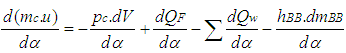
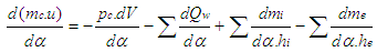
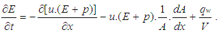
- The Cylinder, High Pressure Cycle, Basic Equation.The calculation of the high pressure cycle of an internal combustion engine is based on the first law of thermodynamics:
 | (1) |
 = change of the internal energy in the cylinder.
 = piston work.
 = fuel heat input.
 = wall heat losses
 = enthalpy flow due to blow-by
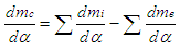
 = blow-by mass flowThe first law of thermodynamics for high pressure cycle states that the change of internal energy in the cylinder is equal to the sum of piston work, fuel heat input, wall heat losses and the enthalpy flow due to blow-by.In order to solve this equation, models for the combustion process and the wall heat transfer, as well as the gas properties as a function of pressure, temperature, and gas composition are required.Together with the gas equation
 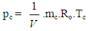 | (2) |
 | (3) |
 | (4) |
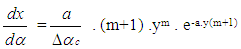 | (5) |
 | (6) |
 | (7) |
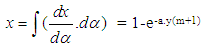 | (8) |
 | (9) |
 | (10) |
 | (11) |
 | (12) |
 | (13) |
 | (14) |
 | (15) |
 | (16) |
 | (17) |
 | (18) |
 | (19) |
 | (20) |
 :
: | (21) |
 | (22) |
 | (23) |
 | (24) |
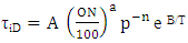
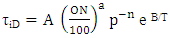
 ignition delayON = Octane Number RequirementA = 17.68 msB = 3800 Ka = 3.402n = 1.7
5. Results and Discussions
5.1. Effect of Air-Fuel Ratio on Octane Number Requirement
- The Fig.1 below shows the computed octane numbers required for both the fuels petrol and ethanol under constant speed and variable load or variable air-fuel ratio operation.
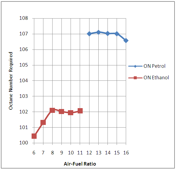 | Figure 1. Effect of Air-Fuel Ratio on Octane Number Requirement |
5.2. Effect of Air-Fuel Ratio on Engine Power
- The Fig.2 below shows the effect of air-fuel ratio on the power developed by the engine under consideration in the petrol and ethanol modes.
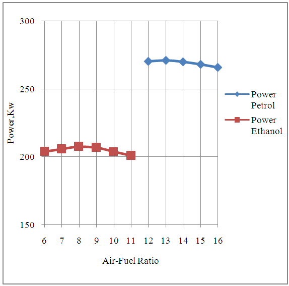 | Figure 2. Effect of Air-Fuel Ratio on Engine Power |
5.3. Effect of Air-Fuel Ratio on Engine Torque
- The Fig 3 below shows the effect of air-fuel ratio on the torque developed by the engine under consideration with both petrol and ethanol as its alternative fuels.
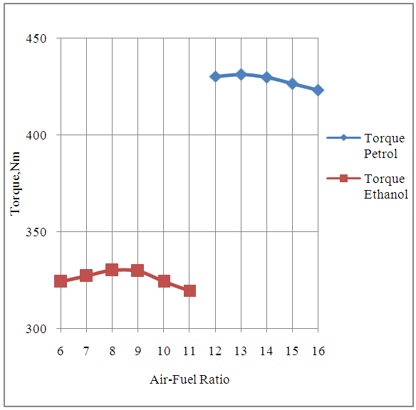 | Figure 3. Effect of Air-Fuel Ratio on Engine Torque |
5.4. Effect of Air-Fuel Ratio on Brake Specific Fuel Consumption
- The Fig,4 below shows the effect of air-fuel ratio on the brake specific fuel consumption of the engine in both petrol and ethanol modes.
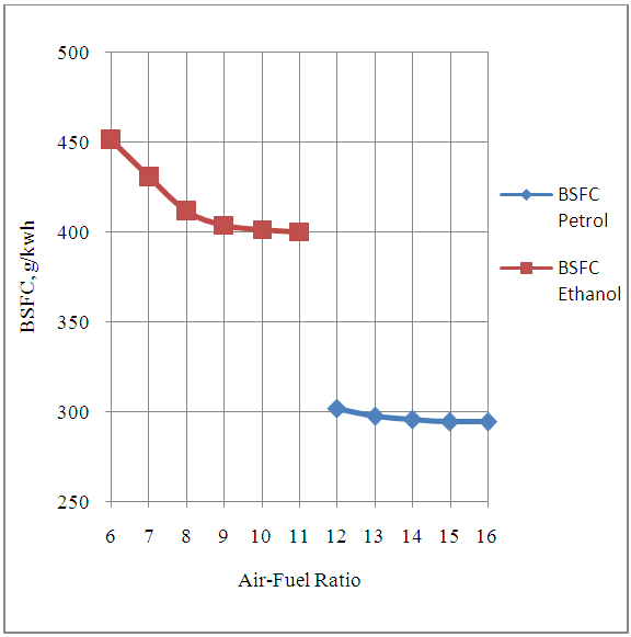 | Figure 4. Effect of air-Fuel Ratio on Brake Specific Fuel Consumption of The Engine |
5.5. Effect of Air-Fuel Ratio on CO Emissions
- The Fig.5 below shows the effect of air-fuel ratio on CO emissions produced by the engine under consideration with both ethanol and petrol as fuels.
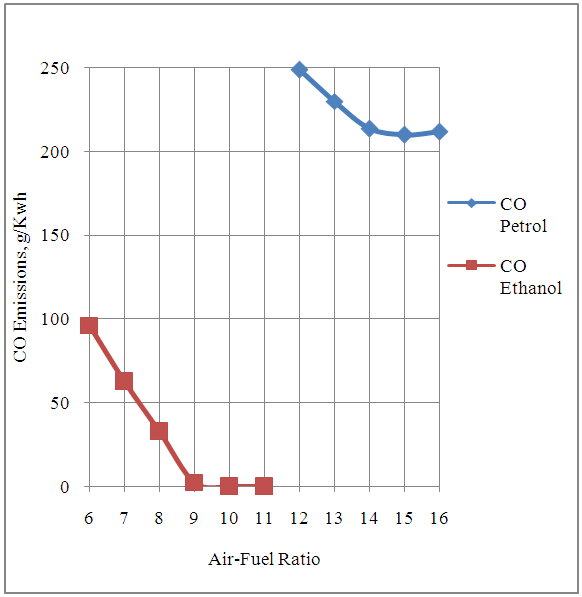 | Figure 5. Effect of air-Fuel Ratio on CO Emissions from the Engine |
5.6. Effect of Air to Fuel Ratio on HC Emissions
- The Fig.6 below shows the effect of air-fuel ratio on HC emissions produced by the engine in ethanol and petrol modes.
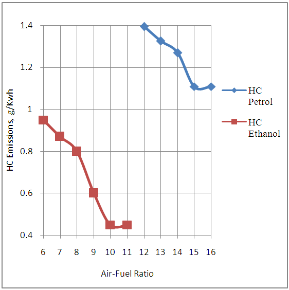 | Figure 6. Effect of Air-Fuel Ratio on HC Emissions of the Engine |
5.7. Effect of Air to Fuel Ratio on NOx Emissions
- The Fig.7 below shows the effect of air-fuel ratio on NOx emissions from the engine with ethanol and petrol as alternative fuels.
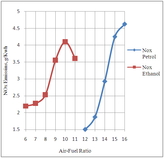 | Figure 7. Effect of Air-Fuel Ratio on NOx Emissions of the Engine |
5.8. Effect of Air to Fuel Ratio on Exhaust Gas Temperature
- The Fig.8 below shows the effect of air-fuel ratio on the exhaust gas temperature of the engine.
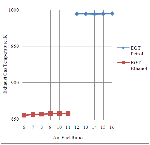 | Figure 8. Effect of Air-Fuel Ratio on the Exhaust Gas Temperature of the Engine |
6. Conclusions
- 1. It is concluded that the commercial naturally aspirated spark ignition engines can be turbocharged successfully for boosting its power with renewable ethanol as its fuel since the higher octane rating of the commercial ethanol suits it.2. It is also possible to boost the power of a petrol or gasoline operated spark ignition engine using a turbocharger provided the octane rating of petrol could be improved in the petroleum refineries.3. The possible use of a turbocharger for a spark ignition engine will downsize the engine displacement volume needed for producing a certain power. This has already been proved in case of diesel operated compression ignition engines.4. In order to design engines which could produce lower CO and HC emissions to meet the future emission norms, it is feasible to the use the renewable ethanol for turbo-charging a conventional naturally aspirated spark ignition engine.5. Since ethanol is a renewable source of energy, under the conditions of non availability or depletion of petroleum resources, it can be considered as a reliable energy source of energy for turbo-charged spark ignition engines.6. The research findings presented in this paper suggest the use of only one high octane number rated fuel ethanol or petrol for the turbocharged version of the spark ignition engine. This will suit the existing electronic fuel injection system used on engines and will be quite simple on an overall basis.The experimental investigations done by other researchers mostly suggest the use of a base fuel along with octane improvers as demanded by the operating load and speed of the engine. This type of design needs multiple fuel supply systems being controlled by a single but more complex microcontroller. The complex fuel system in this case could have more number of fuel tanks, fuel supply lines, sensors and activators, fuel pumps etc. This makes this type of system more costly and more complex.The existing internal combustion spark ignition systems have been designed corresponding to the known octane numbers of the commercial petrol or gasoline. The research methodology adopted and the results presented in this research paper suggests the adoption of same methodology for the design of turbocharged spark ignition engines after investigating and developing high octane number rated fuels. Here the focus has been done on the search of a required but existing fuel having the required octane number or may be the modifications needed to be done in the existing fuels to suit the requirements under turbocharged conditions.
ACKNOWLEDGEMENTS
- Author is thankful to AVL Austria and its unit AVL India Ltd Gurgaon for providing AVL BOOST thermodynamic engine simulation software with free license for academic research purposes.
Appendix-A
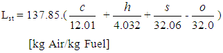
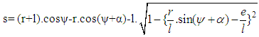
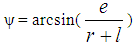
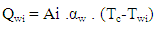
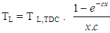
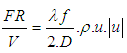
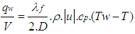
- Nomenclaturea = speed of soundA = pipe cross-sectionAeff = effective flow areaAi = surface area (cylinder head, piston, liner)AFCP = air fuel ratio of combustion productsAgeo = geometrical flow areac = mass fraction of carbon in the fuelcV = specific heat at constant volumecp = specific heat at constant pressureC1 = 2.28+0.308.cu/cmC2 = 0.00324 for DI enginesCm = mean piston speedCu = circumferential velocitycu = circumferential velocityD = cylinder boreD = pipe diameterdmi = mass element flowing into the cylinderdme = mass element flowing out of the cylinderdvi = inner valve seat diameter (reference diameter)
 = blow-by mass flowe = piston pin offsetE = energy content of the gas
 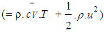 f = fraction of evaporation heat from the cylinder chargeFR = wall friction forceh = mass fraction of hydrogen in the fuelhBB = enthalpy of blow-byhi = enthalpy of in-flowing masshe = enthalpy of the mass leaving the cylinderHu = lower heating valuek = ratio of specific heatsl = con-rod lengthm = shape factor
 = mass flow ratemc = mass in the cylinder mev = evaporating fuelmpl = mass in the plenumn = mass fraction of nitrogen in the fuelo = mass fraction of oxygen in the fuelp = static pressureP01 = upstream stagnation pressurePc,o = cylinder pressure of the motored engine[bar]Pc,1 = pressure in the cylinder at IVC[bar]ppl = pressure in the plenumpc = cylinder pressurep2 = downstream static pressureqev = evaporation heat of the fuelqw = wall heat flowQ = total fuel heat inputQF = fuel energyQwi= wall heat flow (cylinder head, piston, liner)r = crank radiusR0 = gas constants = piston distance from TDCt = time T = temperatureTc,1= temperature in the cylinder at intake valve closing (IVC)Tc = gas temperature in the cylinderTwi = wall temperature (cylinder head, piston, liner)TL = liner temperatureT L,TDC = liner temperature at TDC positionT L,BDC = liner temperature at BDC positionTw = pipe wall temperatureT01= upstream stagnation temperatureu = specific internal energyu = flow velocityV = cylinder volumeV = cell volume (A.dx)VD = displacement per cylinderw = mass fraction of water in the fuelx = relative stroke (actual piston position related to full stroke)x = coordinate along the pipe axisα = crank angleαo= start of combustionΔαc= combustion durationαw = heat transfer coefficientρ = densityμσ = flow coefficient of the portψ = crank angle between vertical crank position and piston TDC position
 = wall friction coefficientΔt = time stepΔx= cell length
|
|