Tha’er O. Sweidan, Mohammed I. Abuashour, Mohammed M. Hattab, Mohammed A. Ma'itah
Electrical Engineering Department, the Hashemite University, Zarqa, Jordan
Correspondence to: Tha’er O. Sweidan, Electrical Engineering Department, the Hashemite University, Zarqa, Jordan.
| Email: |  |
Copyright © 2017 Scientific & Academic Publishing. All Rights Reserved.
This work is licensed under the Creative Commons Attribution International License (CC BY).
http://creativecommons.org/licenses/by/4.0/

Abstract
This paper presents and investigates a new method for analyzing transient stability of a faulted two-machine system by using the numerical simulations in time domain which are executed using MATLAB software package in building the code and by choosing the fault locations and the clearing times. The transient stability analysis of two machine power system subjected to symmetrical three phase to ground fault are conducted at different locations (at line 4-5 near bus 4, at line 4-5 near bus 5 and at the midpoint of the line 3-4) with different clearing times (1, 5, 20, and 100) msec. The transient stability is investigated by solving the nonlinear dynamical second order differential swing equations for the two machines for pre-fault, during-fault and post-fault running periods and new operating points for two machines after clearing the fault are extracted. The fault has been cleared by simultaneously opening the circuit breaker of the faulted line at different clearing times. The rotor angle swing curve for each generator has been presented at different fault conditions. The power system under study consists of 5-bus, with two synchronous generators and two loads.
Keywords:
Transient Stability Analysis, Power System, Swing Equation, Three-Phase Fault, Fault Clearing Time
Cite this paper: Tha’er O. Sweidan, Mohammed I. Abuashour, Mohammed M. Hattab, Mohammed A. Ma'itah, Numerical Simulations for Transient Stability Analysis of Two-Machine Power System Considering Three-Phase Fault under Different Fault Clearing Times and Locations, Energy and Power, Vol. 7 No. 1, 2017, pp. 22-36. doi: 10.5923/j.ep.20170701.03.
1. Introduction
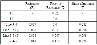
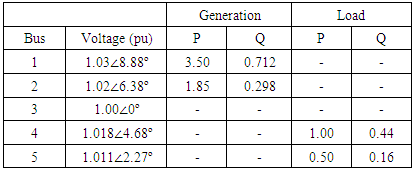
Power system stability is a very important issue for guaranteeing continuous sustainable power transmission to load centers. Power system stability guarantees acceptable operating points under normal operating conditions and to adjust to new acceptable operating points as the power system suffers abnormalities like faults of different types or even under load variations [1]. One of the stability issues is maintaining synchronism among synchronous machines forming up the power system. The power system is continuously subjected to various disturbances. Still, the system and the perturbation sizes caused by specific disturbance in comparison to the size and capability of the whole interconnected systems so that the effects on the system could not predicted [2]. Large disturbance occurs on the power system like severe lightning strikes, and loss of transmission line. The ability of power system to maintain the power flow following a large disturbance and sustain an acceptable operating condition is called transient stability. Power systems disturbances in general are small or large. Small disturbances are in the form of load changes which occur continuously; the power system must have the ability to adjust to these ever changing conditions and to adjust and stay in satisfactory operating points. Also the power system must withstand numerous severe disturbances like a short circuit on a transmission line or loss of a large generation units. Large disturbances lead to major grid structural changes due to the isolation of the faulted elements through the protection systems. At equilibrium state, the power system might be stable for some large disturbances, and unstable for others. It is unfeasible and wasteful to design power systems to be stable for every possible disturbance. The design contingencies and constraints are chosen on the basis of their probability of occurrence. Since, large-disturbance stability refers to identified disturbance situations; the response of the power system to a disturbance involves most of the generating units. For example, a fault on a critical unit followed by its isolation by protective relays will cause variations in power transmitted, bus voltages, and machine rotor speeds; the voltage variations actuate the automatic voltage regulators of the generators to control the reactive power capabilities whereas the generator speed variations actuate turbine governors to vary their power capabilities; Furthermore, protection apparatuses respond to these variations in system operating points and cause tripping of the equipment, so the system possibly becomes instable [3]. But after the disturbance has occurred the power system is stable, it will reach a new operating equilibrium state and the system integrity is preserved. Some generation units and loads might be disconnected by the isolation of faulted parts or intentional tripping through load shedding to preserve the continuity of operation of the system. The operation of automatic controllers and operator’s intervention will ultimately restore the system to its normal state of operation. On the contrary if the system is unstable, it causes a runaway situation; because of the progressive increase in the angular displacement between the generators’ rotors, or a progressive collapse in bus voltages [4]. An unstable system condition might cause cascading outages and a shutdown of a major portion of the power system. In this paper transient Stability for tow machines power system is analyzed and highly investigated under various running conditions. SYSTEM CONFIGURATION AND DESCRIPTIONFigure 1 shows a single line diagram for the power system under study. It comprises 5 buses, two synchronous generators with finite inertia, 230 kV transmission lines and an infinite bus. The two generators are connected to the system via two step up transformers. Bus 4 and bus 5 are load buses, where bus 3 is an infinite bus. In this system the transient stability analysis is carried out, as the system has undergone a symmetrical three phase to ground fault at different locations with different clearing times. In appendix B Table 1 and Table 2 provide the simulated data for the power system under study. All values are in pu (230 kV and 100 MVA base) [5].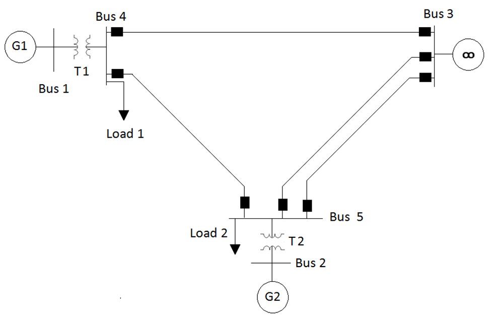 | Figure 1. Schematic diagram of the power system under study |
2. Mathematical Model for Multi Machine System in Transient Stability Study
The admittance Ybus Matrix for the proposed Power System for the 5- Bus is [6]. 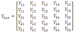 | (1) |
The Electrical power for any bus in the system is given by the following equation: | (2) |
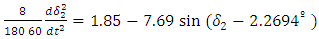
The swing equation is [6]: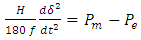 | (3) |
The swing equation is nonlinear second order differential equation and can be transformed into two nonlinear first order differential equations with two state space representation  as follows[7].
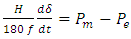 | (4) |
 | (5) |
In the stability studies the loads is converted into shunt admittance as this formula [7].  | (6) |
3. Numerical Simulations and Discussions
This section presents and illustrates the extensive numerical simulations of the transient stability analysis of the power system under study after being subjected to three-phase to ground fault at different locations and with different fault clearing times. The fault has been cleared by simultaneously opening the circuit breakers of the faulted line at different clearing times and the stability of the system is investigated after clearing the fault. In this paper a numerical simulation is carried out for obtaining the delta angle, generator’s speed and the active power of each machine by solving the swing equations for the two machines at pre-fault, during-fault and post-fault running conditions. There are three cases of this study: case 1 when the fault is occurred at line 4-5 near bus 4, case 2 when the fault is occurred at line 4-5 near bus 5 and case 3 when the fault is occurred at the midpoint of the line 3-4. For every case different clearing time is used and the stability analysis is investigated.Case 1: Three-phase fault at line 4 - 5 near bus 4Pre-Fault running conditions admittance Ybus Matrix and swing equations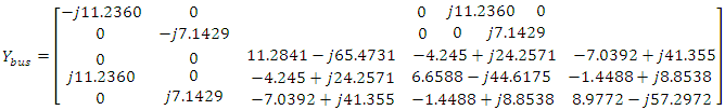 | (7) |
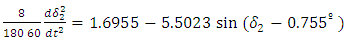
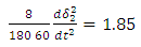
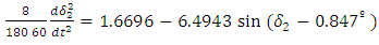
The pre-fault swing equation for generators 1 and 2 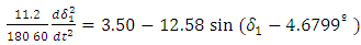 | (8) |
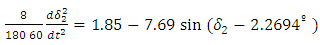 | (9) |
During-Fault running conditions admittance Ybus Matrix after Kron Reduction method to reduce the 5 bus matrix into 3 bus matrix 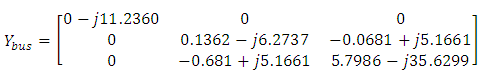 | (10) |
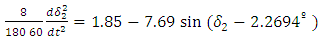
The during Fault Swing equations for generators 1 and 2, the electrical power of generator 1 is zero because the fault is close to bus 4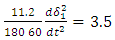 | (11) |
 | (12) |
Post-Fault running conditions admittance Ybus Matrix after Kron Reduction method to reduce the 5 bus matrix into 3 bus matrix 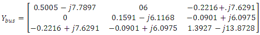 | (13) |
The post Fault Swing equations for generators 1 and 2 become: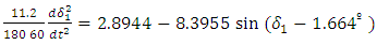 | (14) |
 | (15) |
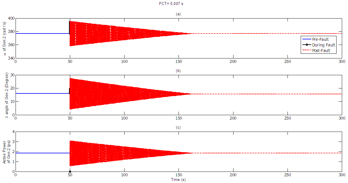
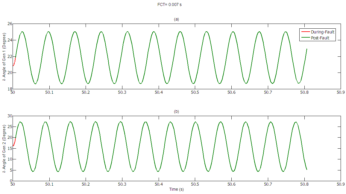
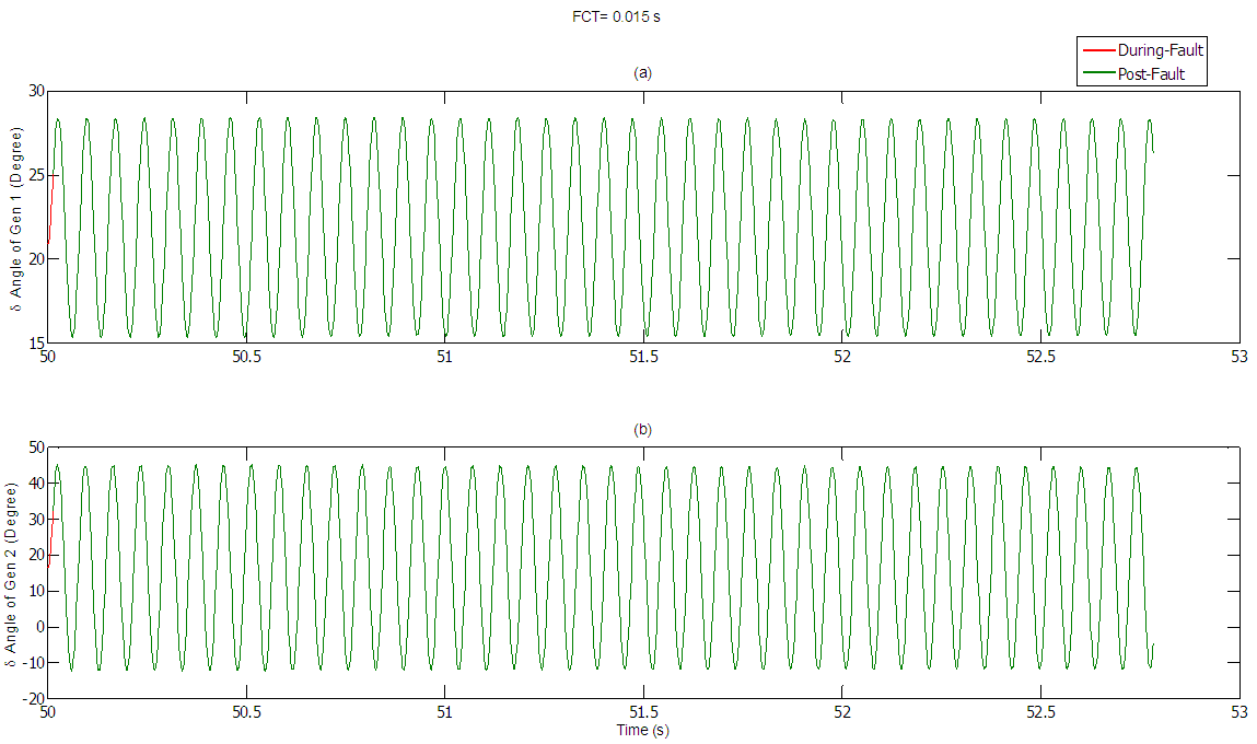
When the line 4-5 is subjected to a three phase to ground fault near bus 4, the power output from Gen1 becomes zero during fault period. The fault has been automatically cleared by simultaneously opening the circuit breaker of the line 4-5. The simulation is carried as follows: Firstly the fault is cleared after 5 ms, Figure 2 and Fig.3 show the delta angle, which has changed from 20.83° to 21.83° for Gen 1, and from 16.19° to 15.74° for Gen 2, the speed of rotation remains at the synchronous speed for both machines of 377 rad/sec and the active power generated also remains constant of about 3.5 and 1.85 pu for both generating units, respectively. Whereas the swing curves for the two machines during fault and after fault has been cleared are shown in Fig. 4. Secondly the fault clearing time is decreased to 1 ms the swing curves during fault and after fault has been cleared are shown in Fig. 5. Similarly, the fault clearing time is increased to 20 ms the swing curves for both machines during fault and after fault has been cleared are shown in Fig. 6. Finally the swing curves during fault and after fault has been cleared for both machines at 100 ms clearing time are presented in Fig. 7.From the system numerical analysis and results it can be clearly concluded that the system shows ruggedness and reliability in its operational behavior as it can adjust rapidly to its new operating points and stay running satisfactorily but the system enters the runaway condition as the fault clearing time is dramatically increased. 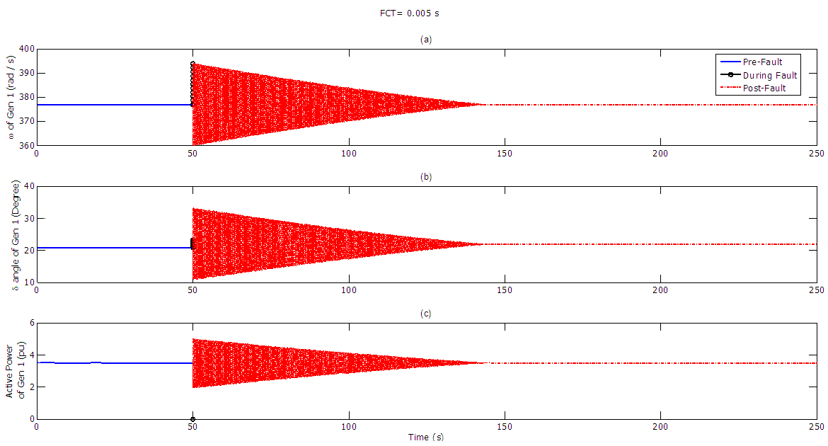 | Figure 2. (a) Speed (b) Delta angle (c) Active power generated by machine 1 at pre-fault, During-fault and post-fault running conditions |
 | Figure 3. (a) Speed (b) Delta angle (c) Active power generated by machine 2 at pre-fault, During-fault and post-fault running conditions |
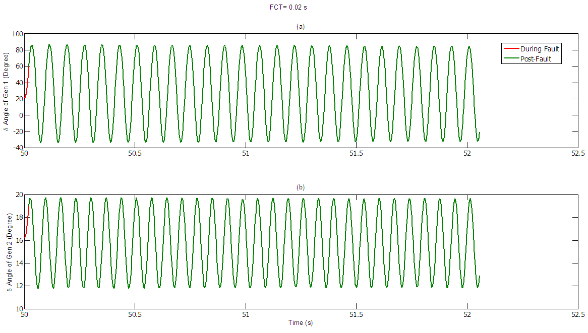
 | Figure 4. (a) Swing curve for machine 1 (b) Swing curve for machine 2 at 5 ms FCT |
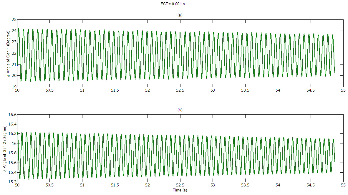 | Figure 5. (a) Swing curve for machine 1 (b) Swing curve for machine 2 at 1 ms FCT |
 | Figure 6. (a) Swing curve for machine 1 (b) Swing curve for machine 2 at 20 ms FCT |
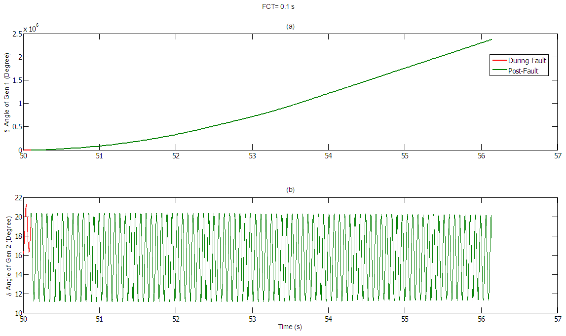 | Figure 7. (a) Swing curve for machine 1 (b) Swing curve for machine 2 at 100 ms FCT |
Case 2: Three-phase fault at line 4 - 5 near bus 5Pre-Fault running conditions admittance Ybus Matrix and swing equations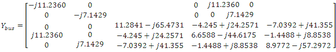 | (16) |
The pre-fault swing equation for generators 1 and 2 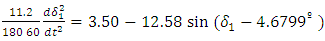 | (17) |
 | (18) |
During-Fault running conditions admittance Ybus Matrix after Kron Reduction method to reduce the 5 bus matrix into 3 bus matrix 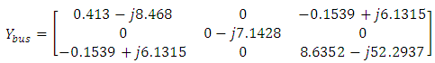 | (19) |
The during Fault Swing equations for generators 1 and 2, the electrical power of generator 2 is zero because the fault is near bus 5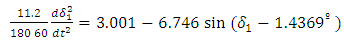 | (20) |
 | (21) |
Post-Fault running conditions admittance Ybus Matrix after Kron Reduction method to reduce the 5 bus matrix into 3 bus matrix 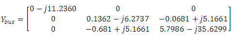 | (23) |
The post Fault Swing equations for generators 1 and 2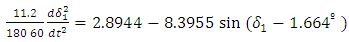 | (24) |
 | (25) |
When the line 4-5 is subjected to a three phase to ground fault near bus 5, the power output from gen2 is zero during fault. The fault has been cleared by simultaneously opening the circuit breaker of the line 4-5. Firstly the fault is cleared after 5 ms. Figure 8 and Fig. 9 show the delta angle which has changed from 20.83° to 21.83° for Gen1 and from 16.19° to 15.74° for Gen2, the speed of rotation remains at the synchronous speed of 377 rad/sec for both machines and the active power generated remains constant of about 3.5 and 1.85 pu for both generating units, respectively. The swing curve for the two machines during fault and after fault has been cleared is shown in Fig. 10. As the fault clearing time is decreased to 1 ms the swing curves during fault and after fault has been cleared are shown in shown in Fig. 11. Similarly, the fault clearing time is increased to 20 ms the swing curves for both machines during fault and after fault has been cleared are shown in Fig. 12. The swing curves during fault and after fault has been cleared for both machines at100 ms clearing time are presented in Fig. 13.Once again the analysis results assures clearly that the system shows elegant transition, ruggedness and reliability in its operational behavior as it can adjust to new operating points and stay running satisfactorily but the system enters the runaway condition as the fault clearing time is dramatically increased. 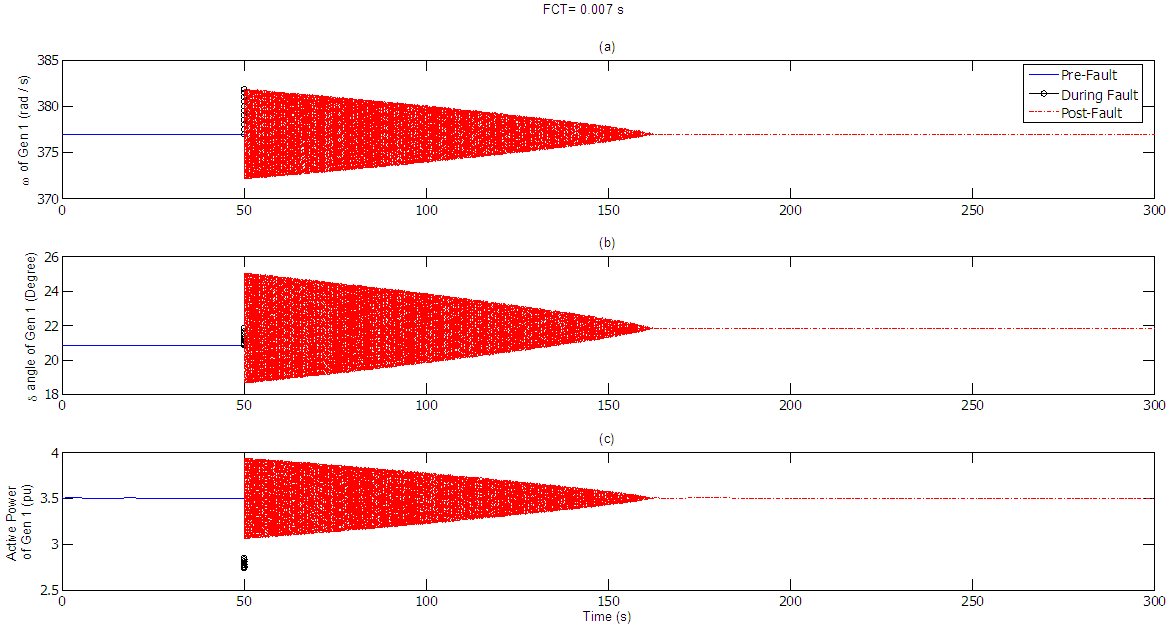 | Figure 8. (a) Speed (b) Delta angle (c) Active power generated by machine 1 at pre-fault, During-fault and post-fault running conditions |
 | Figure 9. (a) Speed (b) Delta angle (c) Active power generated by machine 2 at pre-fault, During-fault and post-fault running conditions |
 | Figure 10. (a) Swing curve for machine 1 (b) Swing curve for machine 2 at 5 ms FCT |
 | Figure 11. (a) Swing curve for machine 1 (b) Swing curve for machine 2 at 1 ms FCT |
 | Figure 12. (a) Swing curve for machine 1 (b) Swing curve for machine 2 at 20 ms FCT |
 | Figure 13. (a) Swing curve for machine 1 (b) Swing curve for machine 2 at 100 ms FCT |
Case 3: Three-phase fault at the midpoint of line 3-4Pre-Fault running conditions admittance Ybus Matrix and swing equations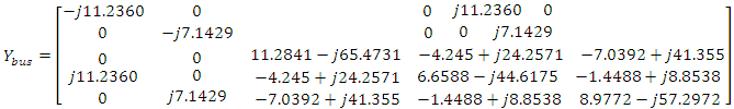 | (26) |
The pre-fault swing equation for generators 1 and 2 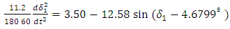 | (27) |
 | (28) |
During-Fault running conditions admittance Ybus Matrix after Kron Reduction method to reduce the 5 bus matrix into 3 bus matrix 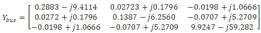 | (29) |
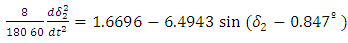
The during Fault Swing equations for generators 1 and 2  | (30) |
 | (31) |
Post-Fault running conditions admittance Ybus Matrix after Kron Reduction method to reduce the 5 bus matrix into 3 bus matrix 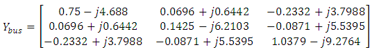 | (32) |
The post Fault Swing equations for generators 1 and 2 | (33) |
 | (34) |
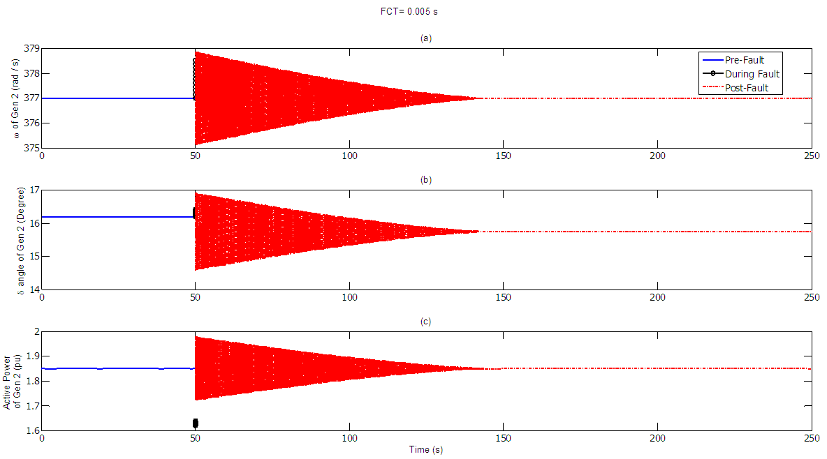
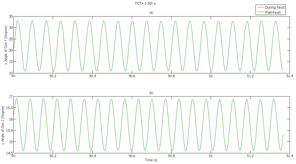
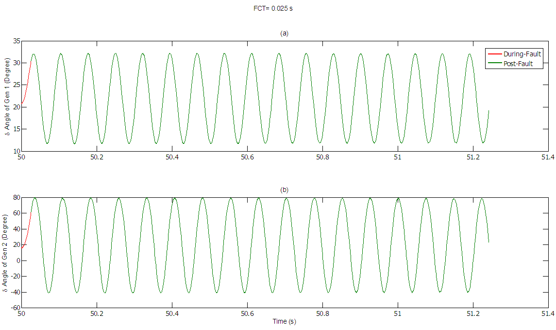
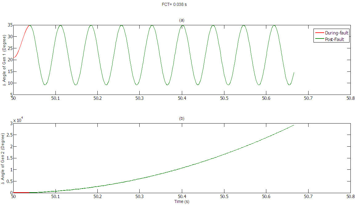
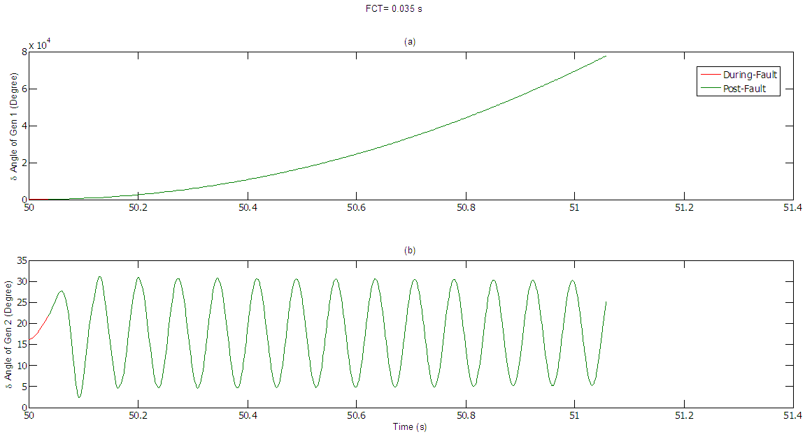
When the line 3-4 is subjected to a three phase to ground fault at its middle portion, the fault has been cleared by simultaneously opening the circuit breaker of the line 4-5. The numerical simulations are carried out as follows: Firstly the fault is cleared after 5 ms and Figure 14 and Fig. 15 show the delta angle of both machines which has changed from 20.83° to 36.63° for Gen1 and from 16.19° to 19.06° for Gen 2, the speed of rotation remains at the synchronism of 377 rad/sec for both machines and the active power generated by two machines also remains constant of about 3.5 and 1.85 pu, respectively. Furthermore, the swing curves for both machines during fault and after fault has been cleared are shown in Fig.16. Secondly the fault clearing time is decreased to 1 ms the swing curves during fault and after fault has been cleared are shown in Fig.17. Similarly, the fault clearing time is increased to 20 ms then the swing curves for both machines during fault and after fault have been cleared are shown in Fig. 18. Ultimately, the swing curves during fault and after fault has been cleared for both machines at100 ms clearing time are presented in Fig. 19.Furthermore, from these extensive analysis and numerical results it is clearly approved that the system continually shows decent swinging by both machines during the fault period, ruggedness, reliability and durability in its performance as it can adjust to new operating points and conditions and stay running satisfactorily, but the system enters the runaway condition as the fault clearing time is considerably increased. 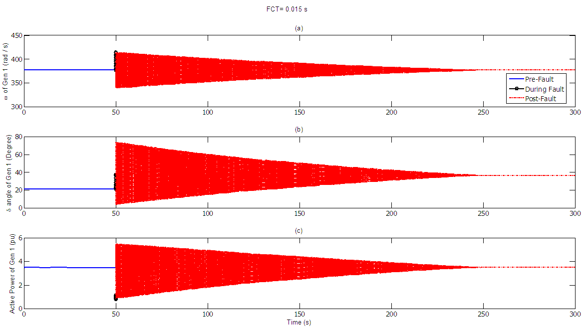 | Figure 14. (a) Speed (b) Delta angle (c) Active power generated by machine 1 at pre-fault, During-fault and post-fault running conditions |
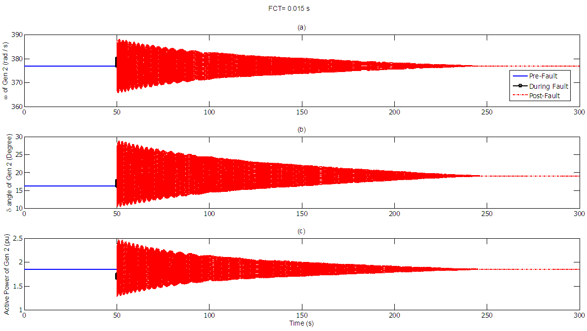 | Figure 15. (a) Speed (b) Delta angle (c) Active power generated by machine 2 at pre-fault, During-fault and post-fault running conditions |
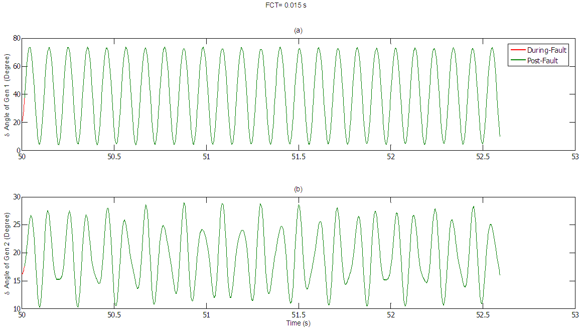 | Figure 16. (a) Swing curve for machine 1 (b) Swing curve for machine 2 at 5 ms FCT |
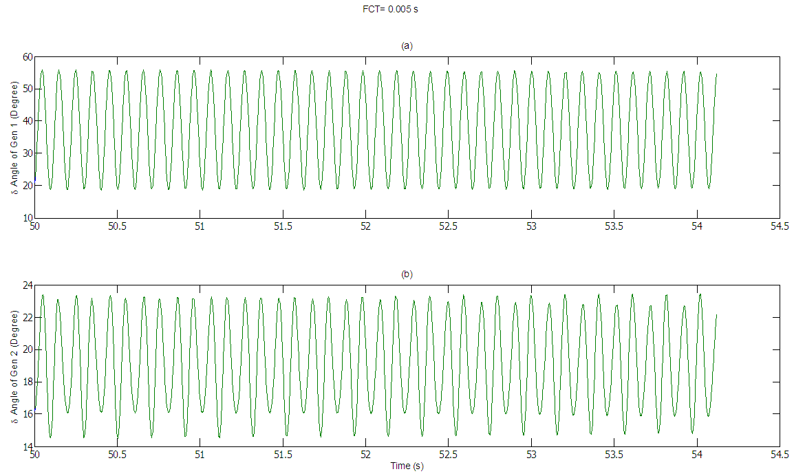 | Figure 17. (a) Swing curve for machine 1 (b) Swing curve for machine 2 at 1 ms FCT |
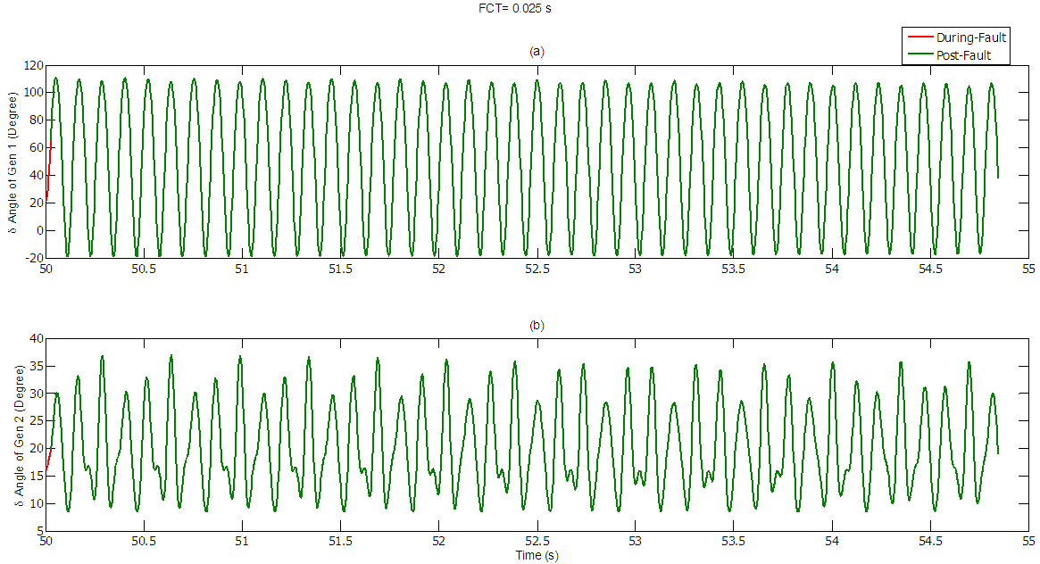 | Figure 18. (a) Swing curve for machine 1 (b) Swing curve for machine 2 at 20 ms FCT |
 | Figure 19. (a) Swing curve for machine 1 (b) Swing curve for machine 2 at 100 ms FCT |
4. Conclusions
The Numerical simulation in time domain for the transient stability of two-machine power system considering three-phase fault under different locations and fault clearing times has been studied and investigated extensively in this paper. It’s clearly shown that the power system stays stable and adjusts decently to new operating conditions under these ever changing conditions but the major factor for this stability state is the fault clearing time that should be well predetermined to ensure system stability and reliability all the time.
Appendix A
The following is the physical explanation for all the system mathematical model parameters The bus active power
 The Kth bus voltage
 The nth bus voltage
 The kith bus Y matrix
 The delta angle of the kth bus
 The delta angle of the nth bus
 The phase angle between the k and n bus
 The moment of inertia constant for the machine
 The mechanical input power for generator
 The bus electrical power
 The operational frequency
 Radian frequency
 Radian synchronous frequency
 Reactive power
 Active power
 Load admittance matrix
  Time differential operator for delta angleFCT: Fault clearing time
Appendix B
Table B1. Transformers and Lines data
 |
| |
|
Table B2. Bus data and Pre-fault load flow values
 |
| |
|
References
| [1] | Huynh Chau Duy, Huynh Quang Minh, “Transient Stability Analysis of Multimachine System” 2003. |
| [2] | Ho Van Hien: Transmission and Distribution of Power System, National University of HoChiMinh City Press, 2003. |
| [3] | Carson W. Taylor: Power System Voltage Stability, McGraw-Hill International Editions, 1994. |
| [4] | Power system stability by Mrinal K Pal. |
| [5] | John J. Grainer, Willam D. Stevenson JR: Power System Analysis, McGraw-Hill International Editions, 1999. |
| [6] | Hadi Saadat: Power System Analysis, McGraw-Hill International Editions, 1999. |
| [7] | Prabha Kundur: Power System Stability and Control, McGraw-Hill International Editions, 1994. |

 Abstract
 Reference
 Full-Text PDF
 Full-text HTML