-
Paper Information
- Paper Submission
-
Journal Information
- About This Journal
- Editorial Board
- Current Issue
- Archive
- Author Guidelines
- Contact Us
Energy and Power
p-ISSN: 2163-159X e-ISSN: 2163-1603
2016; 6(1): 16-20
doi:10.5923/j.ep.20160601.02

Optimal Sizing and Location of the Capacitor Banks in a Radial Industrial Distribution System
 Abstract
 Reference
 Full-Text PDF
 Full-text HTML
Ali K. Dalabeeh1, Abdallah Al-Ziod1, Ayman Hindi2, Ibrahim Al-adwan1, Mohammad Al khawaldah1, Anwar AL-Mofleh1
1Faculty of Engineering Technology, Al-Balqa’ Applied University, Amman, Jordan
2College of Engineering, Najran University, Kingdom of Saudi Arabia (KSA)
Correspondence to: Anwar AL-Mofleh, Faculty of Engineering Technology, Al-Balqa’ Applied University, Amman, Jordan.
| Email: |  |
Copyright © 2016 Scientific & Academic Publishing. All Rights Reserved.
This work is licensed under the Creative Commons Attribution International License (CC BY).
http://creativecommons.org/licenses/by/4.0/

The operation of industrial distribution power systems is accompanied by large losses throughout the feeder due reactive currents. Losses produced by reactive currents can be reduced by the installation of shunt capacitors. The present paper deals with capacitor, installation problem with the nodes of a radial industrial distribution system. An algorithm is proposed to solve this problem such that the economic benefits due to peak power and energy loss reduction are weighed against the cost of installing capacitor bank. The proposed algorithm allows determining the annual saving due to installing the reactive power to each node of the system. The optimum value of reactive power also can be calculated. Using this algorithm the relative saving to the maximum saving as a function of the relative compensated reactive power to the optimal reactive power can be easily found regardless of the distribution and changes of the load along the feeder.
Keywords: Optimal sizing, Capacitor banks, Power losses, Industrial distribution power systems
Cite this paper: Ali K. Dalabeeh, Abdallah Al-Ziod, Ayman Hindi, Ibrahim Al-adwan, Mohammad Al khawaldah, Anwar AL-Mofleh, Optimal Sizing and Location of the Capacitor Banks in a Radial Industrial Distribution System, Energy and Power, Vol. 6 No. 1, 2016, pp. 16-20. doi: 10.5923/j.ep.20160601.02.
Article Outline
1. Introduction
- Studies have indicated that 13% of total power generated is consumed as I2R losses at the distribution level [1]. Reactive currents account for a portion of these losses. Losses produced by reactive currents can be reduced by the installation of shunt capacitors. The use of capacitors in power systems has many well-known benefits which include improvement of the system power factor, improvement of the system voltage profile and reduction of losses due to the compensation of the reactive component of the power flow [2]. Capacitor allocation for loss reduction in the electric distribution systems has been researched over the past several decades. The problem of optimal capacitor allocation involves determining the locations, sizes, and number of capacitors to be installed in a distribution system such that the maximum benefits are achieved while all operational constraints are satisfied at different loading levels [3], [4]. Two approaches to reduce the loss in a distribution system, the first one is to shorten the overall network resistant path that the current is passing through by altering the network topology, which is known as reconfiguration [5]. The second approach is to reduce the branch current that comes from root buses to loads by installing shunt capacitor banks in the network [6-11].According to the records of the meter instruments available on both the sending and receiving ends of the lines, losses in the transmission system can be simply calculated. While in distribution components, there is no comparable source of information available and the losses in them must be calculated from known circuit parameters and loads [12]. The optimum size and the location of the capacitor can be determined on the basis of the maximum peak power and the energy loss reductions [13], [14]. Most of the present methods developed for optimal shunt capacitor placement problems are suited for fundamental frequency signals, and the effects of harmonics are completely ignored [15-17]. Substantial research has been carried out on the solution of optimal capacitor placement planning in the distribution systems for the purpose of power factor correction, voltage profile improvement and loss reduction. Especially, industrial plant with variable load conditions has large inductive loads and its power factor is very poor. These industries benefit most from capacitor banks. In most of the cases, the main reason for the installation of capacitor banks by consumers is to avoid penalty in the electricity bill [12]. The compensating capacitors are placed at these optimal locations; several methods of loss reduction in distribution system have been reported over the years. Control of reactive power in distribution systems with an end-load and fixed load and varying load conditions have been reported giving generalized equations for calculating the peak power and energy reductions and the optimal locations and rating of the capacitors. Other studies have been reported on reactive power compensation that used uniformly distributed load [2], [18], in recent years, there has been an urgency to increase the efficiency of the power system in order to accommodate higher loads and overcome delays in the construction of new generating facilities arising from environmental concerns and high investment costs [2]. The goal is to minimize the overall cost of the total real power loss and that of shunt capacitors [20], [20]. The problem was commonly resolved by using mathematical programming techniques [4], [15], [22]. Most of the previously reported work on capacitor location has been done in uniform load feeders. Very little information is available in the literature on the locating and the rating of the capacitors for non uniform and variable loads. In this paper the optimum location, the annual saving of adding a capacitor bank to a node in the radial industrial distribution have been investigated. The optimal value of the capacitor bank has been determined which corresponds to the maximum value of annual saving. The proposed algorithm can use for a uniform of a no uniform distribution feeder unlike the previous works which concerned only of uniform feeders. The following paragraphs describe a method of calculating the power and energy losses in distribution primary feeders and present general equations for the determination of best location, the optimal value of the connected capacitors, and the corresponding of the annual saving gained from such connection.
2. Mathematical Modeling
- Consider a radial industrial distribution system of n-nodes with reactive power of
 in each node. If a capacitor bank with reactive power of
  Is connected to node I to compensate the reactive power and to reduce the power and energy losses and suppose that the annual saving in $/year due to installing the
  To the node I is denoted by
  Then the rate of change in the annual saving with respect to the reactive power to be installed is defined as follows:
 | (1) |
 The annual saving due to installing reactive power
  at node i. It is given by [5]:
 | (2) |
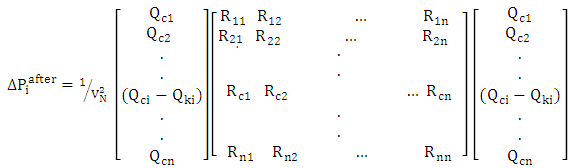
 The active losses before installing the capacitor bank at i-th node.
 The active losses after installing the capacitor bank at i-th node.β: The active power price.T: Time of service for (C.B) /year. (service duration)
  The reactive power price.
 The cost of the KVAR unit of the installed capacitor unit.ρ: The total coefficient as a percentage of capital cost, deducted from capital investment due to repair (maintenance) and salaries.Both
  And
And  are defined by the following equations:
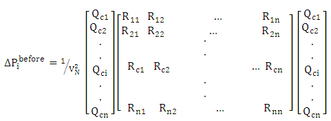 | (3) |
 | (4) |
 The nominal voltage.
 The reactive power connected at i-th node
 The input resistance of the i-th node.
 The mutual resistance between i-th and j-th nodes.n: Number of load nodes. Substituting equations (3) and (4) into the equation (2) yields:
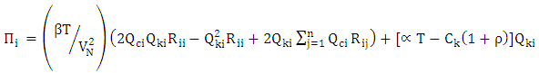 | (5) |
 which corresponds to the maximum value of annual saving can be obtained by differentiating equation (5) and equating the result to zero, then:
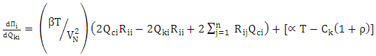 | (6) |
 | (7) |
 According to equation (7) into the equation (5) gives the maximum amount of annual saving:
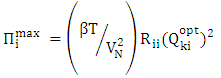 | (8) |
 | (9) |
 | (10) |
 | (11) |
3. Analysis and Discussion
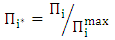
- The relative saving with respect to maximum saving and the installed reactive power with respect to the optimal reactive power
 can be illustrated using figure 1. As seen from the figure if the installed reactive power is zero, then relative saving will be zero, it is similar to the case of installing reactive power equals twice the optimal value. As a result, if the relative installed reactive power ranges between zero and one then the relative saving increases at a positive, direct, while if the relative installed reactive power ranges between one and two, then the relative saving decreases in a negative direction.
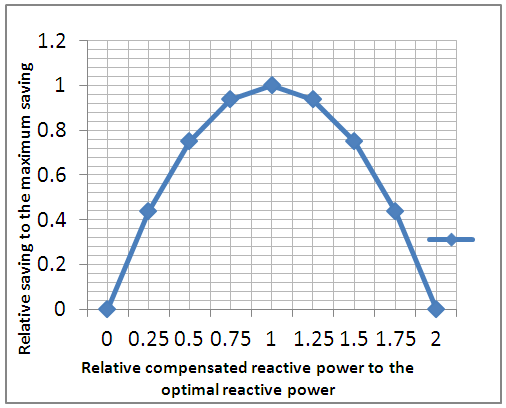 | Figure 1.  |
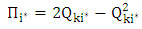
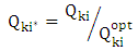
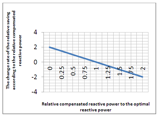
 with respect to the relative installed reactive power with respect to the optimal reactive power
  can be obtained using the following equation:
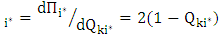 | (10) |
 | Figure 2.  |
 is equal to 1, which means that the connected compensated reactive power equals to the optimum reactive power, the rate change of the relative saving is equal to zero. But when there is no compensated reactive is connected to the node i , the rate of change in the relative saving is maximized and reach the value of positive 2, which implies the necessity to connect a capacitor bank. The opposite case takes place when connecting a double value of compensated reactive power to the node i, the rate of change in relative saving reaches a maximum value but in negative sign which is financially not acceptable. A simple test-system can be used representing a practical application. Consider a simple distribution system with the following data:The nominal voltage is 10kV and has two nodes, at node number one a reactive load of 20kVar is connected while a 30kVar is connected to node number 2.
  And
And  . The commercial data for the system are as follows: β=0.17 Jordanian dinars (J.D) per kWh; α=0.0015 J.D/kVarh, ρ=0.17, and
  .
. 3.1. Case One
- A different values of bank capacitors are added to node number one, the annual saving due to installing reactive power
 can be determined using equation number 5. The obtained results are presented in Table 1:
|
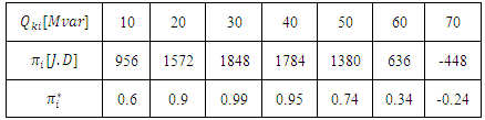
 which corresponds to the maximum value of annual saving can be obtained using equation.7 is:
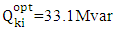 , while the maximum amount of annual saving
  that can be obtained using the equation.8 is:
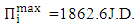 Using equation (10) the relative saving with respect to maximum savings,
  , can be easily calculated. The results presented in Table 1.
3.2. Case Two
- The same values of bank capacitors are connected to node number two. The obtained results using, also, the same equations are presented in Table 2:
|
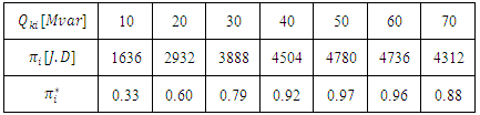
 connected to node 2 which corresponds to the maximum value of annual saving using equation.7 is
  , while the maximum amount of annual saving
  using equation. 8, is
  . The obtained results revealed that the best location (optimal) for adding a bank of capacitors is node number two where the maximum value of annual saving reaches a figure of 4883.3 J.D (much larger than 1862J.D in case of connecting to node number one). A second worthy note is: as the value of capacitor bank close to the optimal value, the profit (annual saving) becomes larger, this is clear in the case of adding 50Mvar to node number two where the obtained annual saving close to the maximum value of annual saving (4780J.D which is equal to 97% of maximum value of annual saving). It is not beneficial to add a capacitor with a value larger than that of the optimal value, because besides the cost of the excess value of the added capacitor the annual saving deeases, which may lead in some case to an economical loss (the annual saving has a minus sign which results), this is clear in the case of adding 70Mvar to node number one, the obtained annual saving becomes minus 448J.D.
 4. Conclusions
- The relative saving of installing a bank of capacitors in an industrial distribution system depends on the relative compensated reactive power which varies from zero to two (or 0% to 200%). As the compensated reactive power increases from 0 to optimal value, the annual saving increases while the rate of change in relative saving decreases. Further increases in the compensated reactive power will lead to a reduction in the relative annual saving while the rate of change in the relative saving increases. So the optimal value of the installed compensating reactive power and the location are essential in the operations of the industrial distribution systems.