-
Paper Information
- Paper Submission
-
Journal Information
- About This Journal
- Editorial Board
- Current Issue
- Archive
- Author Guidelines
- Contact Us
Energy and Power
p-ISSN: 2163-159X e-ISSN: 2163-1603
2015; 5(1): 1-9
doi:10.5923/j.ep.20150501.01
Numerical Simulation of a Segmented Thermoelectric Generator
 Abstract
 Reference
 Full-Text PDF
 Full-text HTML
Hossein Karami Lakeh1, Reza Hosseini Abardeh1, Hassan Kaatuzian2
1Mechanical Engineering, Amirkabir University of Technology, Tehran, Iran
2Electrical Engineering, Amirkabir University of Technology, Tehran, Iran
Correspondence to: Reza Hosseini Abardeh, Mechanical Engineering, Amirkabir University of Technology, Tehran, Iran.
| Email: |  |
Copyright © 2015 Scientific & Academic Publishing. All Rights Reserved.
In the present study, a sample segmented thermoelectric generator has been simulated by finite element method. From numerical solution of this sample, the effect of three important parameters on the performance of segmented TEG was surveyed. The results showed that increase in hot side temperature from 700 to 1000 K causes a considerable increase in the ratio of maximum possible efficiency to the Carnot efficiency from 14 to 19. Also, the output power increased more than 3 time with comparison to the manner 700 K (2 Watt). Then, considering the lateral heat convection between TEG arms and ambient, which almost is neglected in papers, this is specified that increase of convection coefficient from 0 to 30 (W/m2K) causes a decrease in efficiency from 11.5 to 10.5 percent. This value is absolutely significant in the field of thermoelectric specially segmented kinds. The effect of lateral convection on temperature and voltage contours, input heat and the other variables also was surveyed. Finally, the effect of external load by comparison between two manners of maximum efficiency and maximum power was studied. This is specified that voltage and current respectively in the first and second manners are more than the corresponding values in the other manner.
Keywords: Thermoelectric, Segmented Generator, Finite Element, Energy Conversion
Cite this paper: Hossein Karami Lakeh, Reza Hosseini Abardeh, Hassan Kaatuzian, Numerical Simulation of a Segmented Thermoelectric Generator, Energy and Power, Vol. 5 No. 1, 2015, pp. 1-9. doi: 10.5923/j.ep.20150501.01.
Article Outline
1. Introduction
- The effect of thermoelectric contains Joule, Peltier, Seebeck and Thomson phenomenons. Nowadays, thermoelectric is made by coupling n and p semiconductors. It is applicable in two manner; generator and cooler [1]. It is provable that maximum efficiency of a thermoelectric generator (TEG) and also coefficient of performance of a thermoelectric cooler (TEC) depend on two factors of temperature range
 and figure of merit (
 ) [2]. Figure of merit is a criteria for comparing materials about their thermoelectrical conversion efficiency. It is a relationship between thermoelectric properties such as Seebeck
  , electrical resistivity
  and thermal conductivity
  . Whatever
  for a material be more, it’s thermoelectric power will be more [1-3]. But the main problem is the strong dependency of properties and consequently
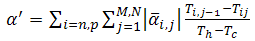
  to the temperature. This matter has been shown in Figure 1. As can be seen in this figure, there isn’t any material that be efficient in all temperature ranges. So, for each application, the appropriate material should be selected. For this reason, one of the most important ways for increasing efficiency of thermoelectric is applying segmented arms. In the significant temperature ranges, thermoelectric arms are made from several materials. A segmented TEG couple has been shown in Figure 2.
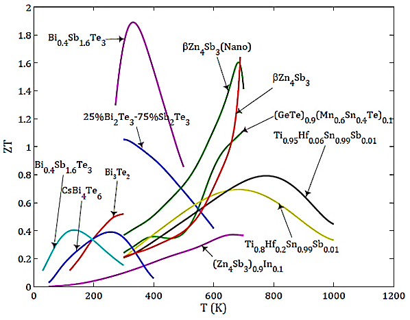 | Figure 1. Temperature dependent dimensionless figure of merit [9] |
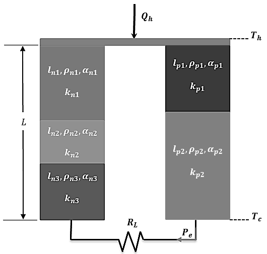 | Figure 2. Schematic of a simple segmented TEG |
 segment in the
  -type (n or p) arm is
  . Similarly,
  ,
,  ,
,  and
and  respectively are thermoelectric properties of each segment and temperature of contact surfaces. Also,
  is length of arms,
  is cross sectional area,
  is input heat to the couple,
  and
and  are hot and cold side temperatures and
  and
and  respectively are load resistance and output power.Segmented TEG has more efficiency in comparison to normal one. For example, Reddy [4] numerically showed that a sample segmented TEG has about 30 percent more efficiency than normal kind in the same condition.From years ago there were a lot of methods for analysis, design and optimization of segmented TEG. For instance, Swanson [5] with an optimization algorithm reached to efficiency of about 11.5 percent. Also, El-Genk [6] by optimizing Swanson’s method, for a space application, designed and tested several samples of TEG from Skutterudite, Bi2Te3 and SiGe. He reached to efficiency of more than 14 percent for temperature range of 573 and 973 K. In these methods for each arbitrary temperature range, at first, appropriate materials with maximum
  are selected. Then, by 1-D finite difference method for a couple, length of each arm, cross sectional area and external load for maximizing efficiency and output power of TEG are calculated.There are various problems which influence on analysis and design of segmented TEG. For example, Kim [7] optimized a TEG with purpose of decreasing price and weight and finally reached to 43 (w/kg) of power for temperature difference of about 500 K. In the other hand, one of the best methods of numerical solution of various physical problems especially electro-thermal problem is finite element method. It is based on converting PDE to ODEs system or ODE to algebraic equations system [8]. Considering the complexity of simulating TEG (that contains two coupled thermal and electrical domains) by FEM, commercial softwares such as Ansys could be applied.Numerous credible articles (such as [10] and [4]) that have studied TEG, have used this software to analyze thermoelectric and achieved to the validated results by theory and experiment. Xiaodong [11] investigated on the thermo-mechanical performance of a segmented TEG under various conditions. He showed that with increase hot side temperature, efficiency of thermoelectric approximately increases linearly with slope of about 0.0175 (percent/K). Constantinos [12] optimized segmented TEG using Bi2Te3 and PbTe for various temperature differences and finally achieved to efficiency of 5.5% for temperature difference of 325 K.But in the present paper, the results of 3-D simulation of a sample segmented TEG has been represented in detailed. Throughout this study, the effect of lateral convection heat transfer from TEG’s arms that is ignored in almost all papers has been investigated with FEM and strongly discussed. For example, Ming [13] did an excellent numerical study on STEG1 by Ansys and presented very useful results for a TEG with maximum efficiency of 11.2%. But he ignored lateral convection.In this matter, Mackey [14] developed a model for NASA that could estimate the effect of lateral convection on the normal TEG (not segmented) made from SiGe. He predicted a decrease in efficiency from 6.15 to 5.23% for a special manner of convection. In his work, although 1-D temperature distribution in the arms has been obtained for various conditions; but the effect of convection on temperature distribution in each section which is determined effective temperature of that section, has been ignored. Also, his model is not extendable to segmented TEG. But, Vikhor [15] could extract a novel computational model to estimate segmented thermoelectric performance and achieved to the value of 7.5 percent for a BiTe-based material TEG which verified by experiment. His model also could use for segmented cooler [16]. But it was 1-dimensional and although it has been developed for segmented TEG, but lateral convection in this model is ignored.Another point is that in the present work, 3-D temperature and voltage distributions are illustrated and discussed. The results with attendance of lateral convection are very different from 1-D manner. Also, numerical solution for segmented TEG (3D) that is very more complicated than normal TEG (even 3D, although numerous articles have been studied 1D), has been presented. Finally, the effect of changing hot side temperature and external load have been deeply studied.
 2. Governing Equations
2.1. Temperature Distribution and FEM
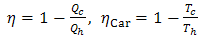
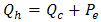
- TEG such as each thermodynamic system works between two thermal sources:
 | (1) |
 and
and  respectively are heat transferred to (from) cold and hot source and
  is Carnot efficiency of system. Carnot efficiency shows the maximum efficiency of a system between two temperature
  .Heat transfer in two side of TEG is result of Peltier, Joule and thermal conduction that for knowing them, temperature distribution must be available [2]. Temperature distribution along a TEG couple in presence of Thomson effect is equal with [2]:
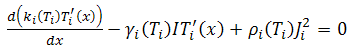 | (2) |
 shows arm type (n or p),
  is Thomson coefficient and
  and
and  respectively are electric current and current density per cross sectional area. It should be mentioned that in this equation lateral surfaces of arms are insulated.As can be seen in this equation, the coefficients that are thermoelectric properties, are temperature dependent. This matter has caused more complexity and consequently there is no strong analytical solution until now. Considering FEM the important variables of TEG could be presented as [17]:
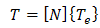 | (3) |
 | (4) |
 and
and  are vectors of nodal temperature and voltage respectively and N is shape function. Applying equations (3) and (4) to the equation (2), finite element model of thermoelectric is converted to [17]:
 | (5) |
 and
and  are respectively capacitive and conductive properties. This equation in steady state manner will be simpler. By Ansys, equation (5) could be solved and distribution of temperature and voltage be obtained.
2.2. Segmented Thermoelectric
- Swanson [5] proposed below algorithm to design segmented thermoelectric:1. Calculating thermal average of properties.2. Initial estimation of segments’ length
 with equality of conduction heat flux between two segments.3. Calculating optimum ratio of cross sectional area of two arms
  and optimum ratio of load and internal resistances
  by available relations.4. Calculating electric current and other parameters.5. Modifying the guess for lengths and repeating steps 3 and 4 while value of calculated current do not vary. Thus, length of each segment is obtained. But El-Genk in 2003 mentioned some errors for this method and modified the algorithm. Some benefits of new method are [6]:a. Applying volume average of properties instead thermal average. Equations (6) and (7) show respectively volume average and thermal average of electrical resistivity:
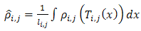 | (6) |
 | (7) |
 . While, in the old method this equation is not exactly satisfied (
 is power output). d. Satisfying the optimum ratio of resistances
  in the maximum efficiency manner. While, in the old method, maximum efficiency occurs not exactly for
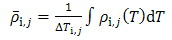
  .El-Genk compared his model for temperature range of 300 to 973 K with Swanson’s as Table 1.
|
 | (8) |
 | (9) |
 and
and  are respectively voltage, effective Seebeck coefficient and the number of p and n type segments.
 3. Numerical Modeling by FEM
- Now, in the main part of study, the numerical analysis of a segmented TEG by FEM is considered.
3.1. Modeling
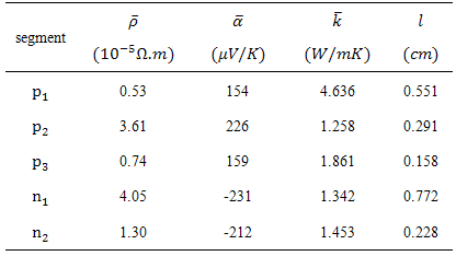
- The thermoelectric couple for temperature range of 300 to 880 K and with specification such as Table 2 has been designed by Swanson [5] optimization method. The ratio of cross sectional area of n to p
 in couple is 1.985. The couple modeled and meshed in Ansys as Figure 3.
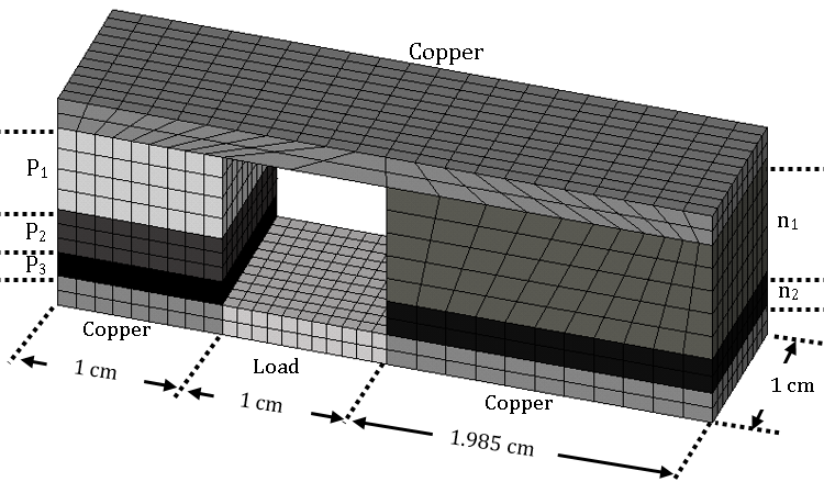 | Figure 3. Modeling segmented TEG couple in Ansys |
|

 is equal with 1.376 that causes maximizing efficiency. Also, copper properties was used for modeling contacts. Thermal conductivity and electrical resistivity of copper respectively was supposed 400 (w/mK) and 1×10⁻⁸ (Ω-m). Seebeck coefficient of copper was supposed zero, although it is actually 5 (µv/K). Finally, contacts between materials were supposed ideal. Then, temperatures of 880 and 300 K were applied to the top and down surfaces (copper surfaces) respectively and voltage of zero (ground) was applied to the down surface of n-type arm (the right arm).
3.2. Results and Discussion
- In the Figure 4, contours and curves of temperature distribution, open and close circuit voltage and vector of electric current in the body of couple that are obtained from Ansys, have been shown. As it is shown in Figure 4-a, temperature is decreasing from 880 K in top surface to 300 K on down surface. Also, temperature gradient is less in the segment with more thermal conductivity.
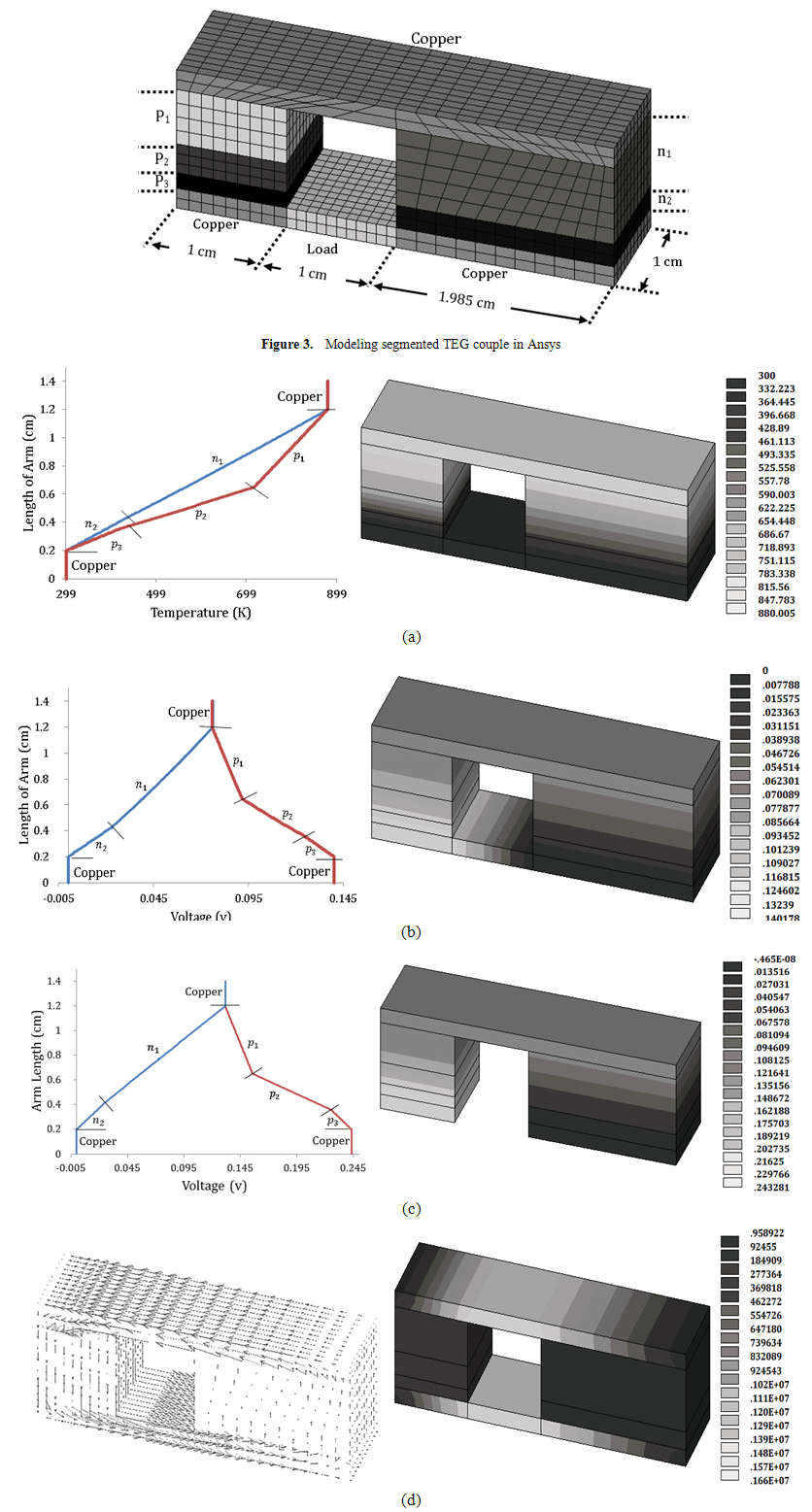 | Figure 4. Distribution of (a) temperature (b) closed circuit voltage (c) open circuit voltage (d) electric current density and its vector |
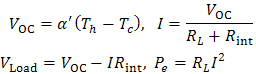
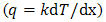 through length of an arm is constant and with increase of thermal conductivity, temperature gradient decreases. Also, temperature in each section of arm is constant. In other hand, there is no temperature gradient in a section. Also, as can be seen in Figure 4-b&c, voltage distribution from zero in down surface of n arm, increases through each segment until upper surface. This ascendant variation will continue from top surface to the down surface of p arm which has maximum value of voltage. This value is 243.281 mv and 140.178 mv for close and open circuit voltage respectively (Figure 4-b&c).This matter absolutely satisfied physical lows. Because, with making thermal difference at both side of n-type semiconductor which has negative Seebeck coefficient, electron flux will release toward cold side that has less level of energy. Consequently, negative electric potential will emerge in this side. In the simulation, this negative potential was supposed ground for making voltage distribution positive. In p-type arm which has positive Seebeck coefficient, holes will treat unlike of electrons in n-type arm. Also, the big difference between two values of open and closed circuit voltage (103 mv) is for potential drop due to resistivity of arms (Joule heat).This potential drop is very close to value of equations (8 & 9). This matter is shown in Table 3. Voltage distribution in load is also linear. Because electric resistivity of material has been supposed constant. Although, it should be mentioned that a very little negative value is observed in Figure 4-b. Electrical vortex due to suddenly change of properties in contacts are the reason of this negative value and it has no influence on accuracy. But with a glance on Figure 4-d, it is considered that electric current density in TEG body is variable. The reason of this problem is also justifiable from TEG physics.
|
 , by the cross sectional area of arms. Also, power output has been obtained from calculation of Joule heat generated in load which is equal with 0.224×10⁸ (j/m3). Another important point about simulation by Ansys is satisfying equations. For example, if power output is calculated by substitution the results of Ansys in both relations
  and
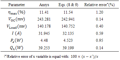
and  , respectively the values of 4.46972 and 4.47797 (w) are obtained. The value read from software is 4.48 (w) which means appropriate accuracy. Now, after presenting FEM simulation, the problem of changing the temperature difference between two sides of TEG is considered. By remaining cold side temperature and changing hot side temperature to 700, 800 and 1000 K, software runs for TEG and its results were obtained as Table 4.
|
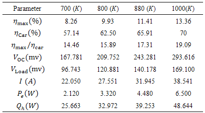
 of 10 and 30 (W/m2K). The ambient temperature also was supposed 300 K.The results of simulation with this two coefficients have been illustrated in Figure 5. As can be seen in Figure 5-a, temperature distribution in the arms is not symmetric further. Which means there is temperature distribution in each section of arms. The reason is that heat transfer with ambient is as more effective as one approaches to the lateral surfaces from central area of each section and so temperature of body is less near the outer surfaces (dark color in figure). Now, if
  changes from 10 to 30 (W/m2K), this event is intensified and curvature of temperature distribution will be more, Also, the same event is going to happen for voltage. As one depart from central area toward outer surfaces of each section, voltage will decrease (Figure 5-b). Another important point is that the maximum generating voltage in TEG has been decreased by entering convection. This occurrence will be intensified by increase of convection coefficient (Figure 5-b). To justify this effect, the physics of thermoelectric must be considered. For increasing generating voltage, temperature difference of TEG must be increased. Although, in this simulation, temperatures are fixed; but as can be found from temperature distributions (Figure 5-a), the effective temperature of each section will decrease by entering convection heat transfer (because of the reason already be mentioned). Thus, the effective temperature which energy conversion occurs in it, decreases and consequently output voltage will decrease. This is one of problems that can differ theoretical analysis from experimental results.
 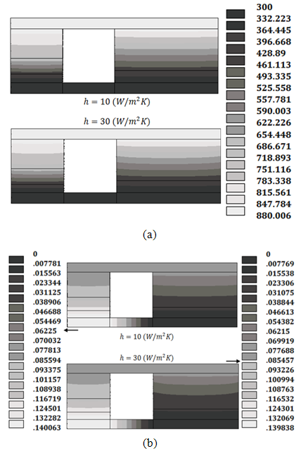 | Figure 5. Distribution of (a) temperature and (b) voltage in arms with convection coefficient of 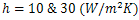 |
 decreases. The reason is decrease of effective temperature along the arms and so increase of temperature gradient and consequently more suction of heat. An important point in this investigation is that in almost all methods of optimization and design of segmented TEG such as Swanson and El-Genk solve the problem by one dimensional approach. So, they can’t estimate contours of temperature and voltage in this situation (with lateral convection). Also, among few 3-D simulations especially those which survey segmented TEG, this matter scarcely has been considered.
|
|
4. Conclusions
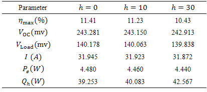
- A proper three dimensional problem in STEG field was comprehensively investigated by FEM.The results showed that for this TEG which works at maximum efficiency manner and between 300 and 880 K, efficiency of 11.41 percent, power of 4.48 watt, current of 32 A and open and closed circuit voltage of respectively 243 and 140 mv are awaited.The effect of increase in hot side temperature from 700 to 1000 K was studied. Considerable increase of efficiency and power respectively from 8.23 to 13.36 percent and 2.12 to 6.5 watt was observed. The variation of efficiency versus hot side temperature was obtained approximately linear with gradient of 0.017.Increase of lateral convection coefficient from 0 to 30 (W/m2K) caused a decrease in efficiency from 11.4 to 10.4 percent. This value of drop in efficiency is very significant in thermoelectric field. Also, temperature and voltage distribution in each section of arms did not retain symmetry anymore after entering convection and were converted to the 3-D curves.Finally, if resistance of external load be in the maximum power manner, comparing with maximum efficiency manner, output current would increase considerably from 32 to 38 A. but voltage would sensibly decrease from 140 to 120 mv.
Nomenclature
Note
- 1. Segmented TEG