-
Paper Information
- Paper Submission
-
Journal Information
- About This Journal
- Editorial Board
- Current Issue
- Archive
- Author Guidelines
- Contact Us
Energy and Power
p-ISSN: 2163-159X e-ISSN: 2163-1603
2014; 4(1): 1-6
doi:10.5923/j.ep.20140401.01
Impact of the Location of a Solar Cell in Relationship to the Focal Length of a Fresnel Lens on Power Production
 Abstract
 Reference
 Full-Text PDF
 Full-text HTML
David Li, Mehtaab Sawhney, Richard Kurtz, Lorraine Solomon, Jeanette Collette
Department of Science, Commack High School, 1 Scholar Lane, Commack, NY 11725, USA
Correspondence to: David Li, Department of Science, Commack High School, 1 Scholar Lane, Commack, NY 11725, USA.
| Email: |  |
Copyright © 2012 Scientific & Academic Publishing. All Rights Reserved.
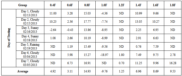
The purpose of this study was to optimize the energy output of solar cells using a Fresnel lens. A Fresnel lens is a flat approximation of the standard convergent thin lens that is able to converge rays of light perpendicular to its surface onto a single point, its focal point, thus concentrating the light energy on a small spot size. To test how Fresnel lenses would impact the energy outputs of solar cells, eight lenses were placed above eight monocrystalline solar cells at heights equal to 0.4, 0.6, 0.8, 1.0, 1.2, 1.4, 1.6, and 1.8 times the lenses’ focal lengths, with an additional solar cell with no lens serving as the control. These setups were tested outdoors for seven days, with the power outputs across 120Ω resistors measured by an Arduino-based data logging circuit. It was found that all experiment groups outperformed the control group in average energy production except for the 1.0F group with the solar cell at the focal length (F), which decreased the energy production by an average of 9.76%. The net increases ranged on average from 1.25% to 14.93% with the 0.8F group performing the best, generating 14.93% more energy than the control. The 1.0F group failed to improve the performance of the solar cell. Findings of the current study indicate that uses of Fresnel lenses with solar cells at optimized lens-solar cell distances could enhance cell output and therefore the practicality of the use of solar energy.
Keywords: Solar energy, Solar panel, Photovoltaic cells, Fresnel lens, Focal length, Power production
Cite this paper: David Li, Mehtaab Sawhney, Richard Kurtz, Lorraine Solomon, Jeanette Collette, Impact of the Location of a Solar Cell in Relationship to the Focal Length of a Fresnel Lens on Power Production, Energy and Power, Vol. 4 No. 1, 2014, pp. 1-6. doi: 10.5923/j.ep.20140401.01.
Article Outline
1. Introduction
- Solar energy is a huge, albeit largely untapped source of electrical energy that can be harvested relatively cleanly. It is estimated for example that the peak insolation in New York State is approximately 500 Watts/m2, and is even higher at lower latitudes, where the sunlight is more direct[1]. However, due to the Shockley-Queisser limit, the theoretical efficiency of even the most efficient monocrystalline silicon-based solar cells is approximately 29%. Current solar panels can only achieve about 18% practical efficiency[2]. The efficiency of silicon solar panels can be further decreased by high temperatures as greater temperatures lower the bandgap of the silicon, making the bandgap less optimized, as less energy from photons that move to the conduction band can be harvested[3]. In fact, it has been shown that the maximum efficiency of a solar panel, as a function of temperature, decreases at a linear rate set by the temperature coefficient[4]. Thus, it is rare that a solar panel can perform at its maximum efficiency because heat is a byproduct of solar radiation[5]. Furthermore, silicon solar panels are very expensive[6], as the silicon must be of high purity (>99.9%) for the solar panel to function properly. Even with tax breaks, a consumer investment in solar energy by installation of solar panels can require as much as 10 years to pay for itself[7]. Such high price and long break-even time are prohibitive for some homeowners and businesses, preventing a broader adoption of solar energy. Therefore, an inexpensive method of increasing the output of a typical silicon solar cell was investigated, thereby improving the power output-to-cost ratio of the solar cell and lessening the break-even time of such an investment. There have been many previous attempts to increase the output of solar cells, and most of them utilized parabolic reflectors, mirrors, and Fresnel lenses for concentrating the solar radiation onto a single point on the solar panels. For example, Mlavsky and Winston[8] designed a solar concentrator that utilized the geometry of a mirror to focus light onto a solar panel positioned at the focal point. Al-Baali[9] reported a two-stage design consisting of a water circulation system and a reflecting mirror for improving the efficiency of solar panels. Dallakyan and Vardanyan[10] developed a cost effective mirror reflecting system to increase the solar energy output. Although some improvements were achieved in certain complicated concentrating systems, the overheating problem for solar panels prevented them from becoming practical[11]. In addition to improvements to existing silicon solar cells, organic polymer[12][13][14] and ceramic[15] solar cells are being developed. A recent breakthrough that could greatly boost the efficiency of solar cells utilized printed colloidal quantum dots as the photosensitive layers to respond to specific wavelengths of light[16]. The purpose of this investigation was to optimize the energy output of silicon-based solar cells using a Fresnel lens by positioning the lenses at different heights above the cells. Unlike the previous Fresnel lens solar concentrator system[8] that positioned the lens at its focal point (1.0F) (Figure 1a), our designs placed the solar cells off the focal point either below or above it (Figures 1b and 1c) to overcome the overheating issue of the solar cells.
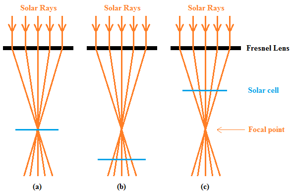 | Figure 1. (a) Previous design, solar cell at the focal point (1.0F); (b) and (c) Our designs, solar cell at off the focal point, either below (>1.0F) or above (<1.0F) the focal point |
2. Materials and Methods
2.1. Materials
- Monocrystalline silicon solar cells were purchased from Electronic Goldmine[18]. They are circular in shape with a diameter of 10.0 cm, producing a maximum of 0.5 V and 1.0 A, with an optimal power of 1 W. Fresnel lenses were obtained from 3D Lens[19], and are made of PVC, having a size of 218 mm × 156 mm × 0.4 mm (about 4 times area of solar cells) with a 0.3 mm groove pitch. The focal length (F) of the Fresnel lenses is 300 mm. Arduino Uno R3 microprocessor from Adafruit Industries[20] was used to build the data logging circuit. All other parts were obtained from RadioShack® and Home Depot®.
2.2. Experiment Designs
- In order to test how the Fresnel lenses will impact the performance of solar cells, and optimize the energy outputs, an experiment setup shown in Figure 2 was designed.
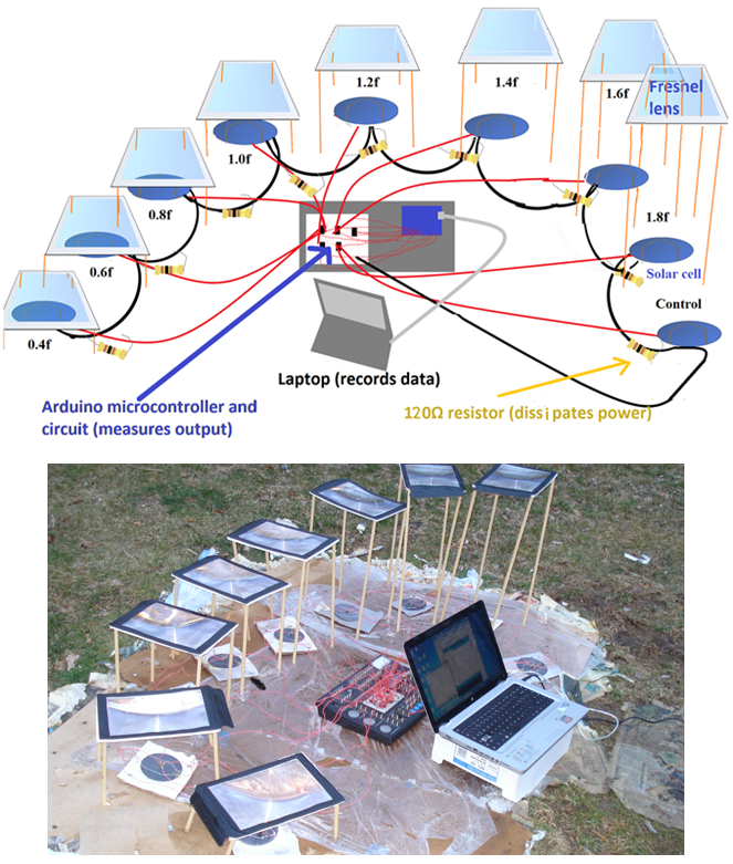 | Figure 2. A schematic representation of the experiment setup (Above) and a picture of the experiment setup (Below) |
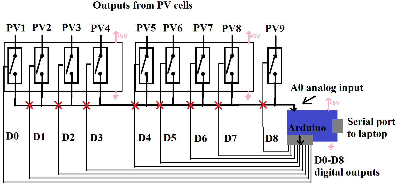 | Figure 3. The specially designed Arduino Microprocessor-based data logging circuit measured the voltage drop across the 120Ω resistor of each of the 9 solar cell setups |
3. Results and Discussion
- The power dissipation of the resistor was calculated by equation 1:
 | (1) |
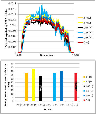
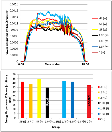 | Figure 4. Power vs. Time graph for a cloudy day (Above). Total energy outputs over a period of 12 hours (Below). Note: Data missing for the 1.2F and 1.8F groups due to data logging error |
 | Figure 5. Power vs. Time graph for a sunny day (Above). Total energy outputs over a period of 12 hours (Below). Note: Data missing for the 0.4F, 1.2F, and 1.8F groups due to data logging error |
4. Conclusions
- In general, positioning the solar cell at a height equal to 0.8 times of the focal length (0.8F) of the Fresnel lens optimized the energy production of the solar cell out of all the setups tested. In every test that was conducted, irrespective of the weather (sunny or cloudy), the energy output of the solar cell at 0.8F was greater than that of any one of the other setups. Furthermore, on average, that configuration improved the energy output by almost 15% compared to the control. The 0.8F distance between the Fresnel lens and solar cell well balanced concentration of the light intensity and minimization of the overheating issue. By contrast, the 1.0F group performed the worst, being the only experiment group that on average lowered the energy output of the solar cell by almost 10%. While being able to concentrate the light rays the most, the 1.0F distance made the sunlight spot too small and might have caused the massive heat problem, which lowered the energy outputs.
5. Applications
- An inexpensive method of increasing solar panel energy production was designed and tested in this investigation, yielding almost 15% average increase in overall energy production in one of the tested prototypes. Such improvement has both implications in residential and commercial purposes. In residential houses, a 15% increase in energy production could decrease the break-even time of a solar investment by 15%, encouraging more people to adopt the solar energy. An increase in solar panel output could also benefit commercial applications by reducing the reliance of fossil fuels that cause great pollution and global warming. Not only is this invention inexpensive, but it is also scalable. Larger solar panels can be fitted with larger Fresnel lenses, and material costs can also be lowered by decreasing the focal length, eliminating the need for long supports that hold the Fresnel lens at a set distance from the solar panel.
ACKNOWLEDGEMENTS
- Thanks go to technology teacher Mr. Joseph Castrogivanni of Commack High School, Mrs. Alison Offerman-Celentano, the Science Director of Commack School District, Dr. Thomas G. Giallorenzi of the Optical Society of America, and Dr. Filiosae of Farmingdale State College for their assistance and helpful discussions.
References
| [1] | Solar Insolation. [Online]. Available:http://neo.sci.gsfc.nasa.gov/view.php?datasetId=CERES_INSOL_M |
| [2] | W. Shockley and H. Queisser, “Detailed Balance Limit of Efficiency of p-n Junction Solar Cells,” J. Appl. Phy., vol. 32, pp. 510-519, March. 1961. |
| [3] | C. Honsberg and S. Bowden. Effect of Temperature. [Online]. Available:http://pveducation.org/pvcdrom/solar-cell-operation/effect-of-temperature |
| [4] | D. L. King, J. A. Kratochvil, and W. E. Boyson, 1997, Temperature Coefficients for PV Modules and Arrays: Measurement Methods, Difficulties, and Results, 26th IEEE Photovoltaic Specialists Conference, Anaheim, California. |
| [5] | C. Hill. The Effects of Temperature on Solar Panel Power Production. [Online]. Available:http://homeguides.sfgate.com/effects-temperature-solar-panel-power-production-79764.html |
| [6] | Complete Solar Panel Cost Guide. [Online]. Available: http://www.solarpanelscostguide.com/ |
| [7] | Why Are Solar Panels So Expensive? Factors That Affect Cost. [Online]. Available:http://www.solarpoweristhefuture.com/why-are-solar-panels-so-expensive.shtml |
| [8] | A. I. Mlavsky and R. Winston, “Solar Cells with Concentrators,” U.S. Patent 4,045,246, Aug. 30, 1977. |
| [9] | A. A. Al-Baali, “Improving the Power of a Solar Panel by Cooling and Light Concentrating,” Solar & Wind Technol., vol. 3, pp. 241-245. 1986. |
| [10] | V. Dallakyan and R. Vardanyan, 2005, Mirror Refelcting Cost Effective PV Solar Energy Concentrating System, 4th International Conference on Solar Concentrators for the Generation of Electricity or Hydrogen, Scottsdale, Arizona, 141–143. |
| [11] | A. Royne, C. J. Dey, and D. R. Mills, “Cooling of Photovoltaic Cells under Concentrated Illumination: a Critical Review,” Solar Energy Mater. and Solar Cells, vol. 86, pp. 451-483. April 2005. |
| [12] | R. Po, M. Maggini, and N. Camaioni, “Polymer Solar Cells: Recent Approaches and Achievements.” J. Phys. Chem., vol. 114, pp. 695-706, Nov. 2009. |
| [13] | L.-M. Chen, Z. Hong, G. Li, and Y. Yang, “Recent Progress in Polymer Solar Cells: Manipulation of Polymer: Fullerence Morphology and the Formation of Efficient Inverted Polymer Solar Cells.” Adv. Mater., vol. 21, pp. 1434-1449, 2009. |
| [14] | R. Gaudiana, “Third-Generation Photovoltaic Technology – The Potential for Low-Cost Solar Energy Conversion.” J. Phys. Chem. Lett., vol. 1, pp. 1288-1289, April, 2010. |
| [15] | N. Gilbert (2013). Nano Ceramics for Sustainable and Efficient Advanced Photovoltaic (PV) Solar cells. [Online]. Available:http://www.azom.com/article.aspx?ArticleID=9174 |
| [16] | A. C. Arango, D. C. Oertel, Y. Xu, M. G. Bawendi, and V. Bulović, “Heterojunction Photovoltaics Using Printed Colloidal Quantum Dots as a Photosensitive Layer.” Nano Lett., vol. 9, pp. 860-863, Jan. 2009. |
| [17] | R. Nave. Fresnel Lens. [Online]. Available:http://hyperphysics.phy-astr.gsu.edu/hbase/geoopt/fresnellens.html |
| [18] | Solar cells. [Online]. Available:http://www.goldmine-elec-products.com/prodinfo.asp?number=G15302 |
| [19] | Fresnel lens. [Online]. Available:http://www.3dlens.com/shop/full-page-magnifying-sheet.php |
| [20] | Arduino Uno R3. [Online]. Available:http://www.adafruit.com/products/50 |