Garry I. Negroni1, Ralph C. Aldredge2
1Institute for Transportation Studies, University of California, Davis, CA, 95616, USA
2Department of Mechanical and Aerospace Engineering, University of California, Davis, CA, 95616, USA
Correspondence to: Ralph C. Aldredge, Department of Mechanical and Aerospace Engineering, University of California, Davis, CA, 95616, USA.
| Email: |  |
Copyright © 2012 Scientific & Academic Publishing. All Rights Reserved.
Abstract
Alternator auxiliary loads affect engine performance and emissions, especially in transient operating conditions. Dynamometer testing of the baseline vehicle with the alternator unplugged suggests that an alternator can produce an auxiliary load even without the presence of a load or pilot excitation and that the auxiliary load increases with engine speed. Vehicle integrated photovoltaic electricity can be used to supplement or complement alternator-based energy storage charging. The efficiencies of the solar panel and charge controller used in this study were estimated from measured data. Accessory loads of the test vehicle were measured for a scenario-based analysis. The scenario-based analysis reveals the limited operating range of the solar electrical system as a restrictive factor for the system’s applicability. Soot opacity tests and dynamometer testing concluded that alternator-less operation improves part-load performance and reduces soot opacity and hydrocarbon emissions. However, from a consumer perspective, the availability of an alternator permits unlimited usage of any “comfort feature” as long as there is fuel energy available without hindrance due to reduced energy availability.
Keywords:
Auxiliary alternator load, Vehicle-integrated photovoltaic, Soot opacity, Particulate matter, Indirect-injection, compression-ignition engine
Cite this paper: Garry I. Negroni, Ralph C. Aldredge, Photovoltaic Charging to Reduce the Alternator Auxiliary Load on a Compression-Ignition Engine, Energy and Power, Vol. 3 No. 4, 2013, pp. 61-66. doi: 10.5923/j.ep.20130304.04.
1. Introduction
Alternator-based charging systems produce auxiliary loads on an engine while providing power for the operation of electrical accessory loads. Auxiliary loads increase fuel consumption and emissions, while decreasing power and torque[1]. Although some electrical loads (such as ignition, spark, or fuel-injection energy) are necessary loads for normal vehicle operations, many electrical loads are optional in nature. Over the past decade, these accessory loads have increased in a trend called “creeping featurism,” where additional, optional features on fleet vehicles have marginally increased electrical demand of onboard alternator-based electrical systems.Subsequently, the fuel consumption requiredfor meeting this electrical demand has increased as well.Efficiencies of energy conversion from fuel to alternator electricityare estimated to be about 21% [1] but vary with engine and alternator efficiencies, engine speed andenergy -storage-device(e.g., battery) state of charge (SOC). When there is no electrical load andthe energy -storage device isat full SOC the alternator operates at low efficiency, with its mechanical energy dissipated as heat. Theinefficiency of the alternator under these conditions increases with increasing engine speed due the increase in alternator capacity with engine speed.Vehicle integrated photovoltaic (VIPV) electricity can reduce peak alternator load requirements, power electrical loads directly, or charge energy storage devices for later consumption. Most VIPV applications focus on enhanced propulsion or extended battery range, for battery-electric vehicles[2, 3] or for reductions in auxiliary loads ofoptional air conditioning systems inhybrid-electric vehicles[4]. With space available on every vehicle’s rooftop, VIPV arrays offer a renewable source of electrical energy decoupled from the primary fuel conversion system. VIPVs can complement or supplement alternator-based charging systems. For seal lead acid (SLA) batteries, commonly used in automotive applications, the topping and floating charge is essential for battery longevity[5]. VIPV charging, as a complement to alternator charging, can help increase battery longevity and performance bytopping-charge enhancement during normal operation and as a float charge during non-operation.The objective of this study is to explore a solar-based primary energy-storage charging system in a light-duty passenger vehicle. Our work presents a blue-sky scenario in which all electrical loads within the test vehicle are supplemented by the solar charging system and energy storage device. The test vehicle was selected for its minimal electrical consumption during normal engine operation. The powerplant of thetest vehicle is a 1.6-Lcompression-ignition engine with indirect mechanical fuel injection. The only electrical load required by the engine is for initial starter power and glow-plug warm up, in addition tocontinuous ignition energy. Our study characterizes the performance of a monocrystalline solar array in conjunction with a pulse-width-modulated (PWM) charge controller and second-life SLA batteries. A comparison is made between the measured and expected performance of thephotovoltaic (PV) charging system, under specifiedweather and solar-angle conditions. The accessory loads of the vehicle are measured and averaged for a scenario-based analysis. Finally, the performance and emissions of the vehicle operating without an alternator (alternator-less) is compared to the performance of the baseline vehicle with the alternator-based charging system engaged. A test is also conducted with the baseline case of alternator-based charging engaged by the engine, but with the alternator disconnected from the energy storage device, in order to determine the alternator’s auxiliary load on the engine when no electrical load or pilot excitation is present.
2. Materials and Methods
Our test vehicle is a 1981 VW Rabbit MK2 DL witha biofuel-capable1.6L MFI IDI compression-ignition engine and a 5-speed manual gearbox. The only auxiliary loads on the engine are the alternator-powered electrical system, water pump, brake booster, and fuel pump. The PV charging system consists of a single 180W Sharp PV Panel, a Morningstar Prostar-30 PWM charge controller, and two second-use 12V, 50AH Optima Red Top lead-acid energy storage devices connected in parallel. The charging system and the energy storage device are connected in series. Figure 1 shows the layout of the VIPV system. National Instruments LABview 2009 was used to acquire voltage and current data. Tests were conducted using Emano 100A/100mV shunts placed between the PV panel, the charge controller, and the energy storage devices. Voltage dropswere measured across the shunts and current was measured across positive and negative terminals ofthe recipient device.Photovoltaic power output from the solar array was measured and compared to available solar irradiation based upon the daily solar constant and atmospheric pollution. Voltage and currentinput (output) to (from) the controller was used to determine its efficiency.The instantaneousinsolation  of a flat, horizontal solar PV panel in units of Wattscan bedetermined from the following relations[6].
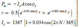 | (1) |
In these relations,  is the daily solar constant (in units of W/m2);
  is the Julian date (numbered consecutively from 1 to 365 for each day of the year, beginning with January 1);
  is the solar-panel area (in units of m2);
  is the zenith angle (formed between the sun rays and the solar-panel normal vector); and the atmospheric transmittance (for a clear, pollution-free sky) accounting for solar-energy absorption and scattering by the atmosphere is denoted by
  . The zenith angle
  is a function of latitude and the time-dependent declination and hour angles and was obtained from the U.S. Navy Solar Angle calculator[7] for each measurement time and location.Local ambient atmospheric conditions were obtained from The Weather Channel[8]. Thesolar-panel efficiency,
  where
where  is the power output from the solar panel, was compared with the solar-array efficiency reported bythe original equipment manufacturer (OEM) to determine the impact of ground-level atmospheric pollution.
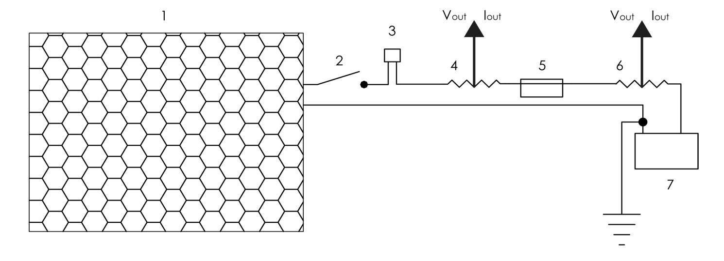 | Figure 1. (Solar-PV charging system):(1) 180W Sharp PV Panel; (2) 600W Emergency Disconnect; (3) 30A Overcurrent Protection; (4,6) Emano 100A/100mV shunts; (5) Morningstar Prostar-30 PWM charge controller; (7) Second-use, 12V Optima Red Top sealed lead-acid batteries, connected in parallel |
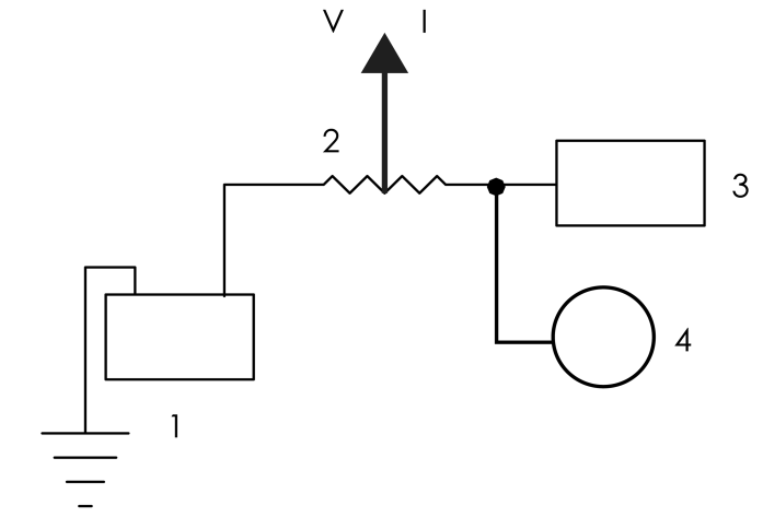 | Figure 2. (Alternator and electrical-load diagram): (1) Energy Storage, (2) Shunt, (3) Vehicle Electrical System, (4) Alternator |
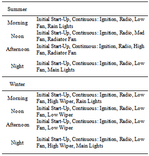
The power output from the PV panel and the charge controller was determined from measurements of output voltages and currents adjusted to account for system noise, calculated with the system disconnected. The average efficiency of the PWM charge controller, defined as the ratio of the power output from the controller to the power input (from the solar panel), was determined based on a range of solar incidence angles, light conditions and battery SOC.Accessory-load tests were conducted toallow assessment of the limitations of solar charging under different seasonal environmental conditions and times of day. These tests involved two season-basedscenarios combining various accessory loads, as summarized in Table 1. Tests were conducted also to determine the electrical accessory loads on the vehicle with the alternator disabled. Figure 2 shows the layout for the accessory-load tests, involving an Emano 100A/100mV shunt placed between the positive terminal of the energy storage device and its primary point of connection with the vehicle electrical system.The voltage drop across the shunt and the current draw of the energy storage device were measured to evaluate the electric accessary-component loads. The radiator-fan input power was calculated using the OEM specification of 12V at 45A [9]. Energy demands for normal vehicle operationinthe accessory-load scenarios outlined in Table 1 are discussed later, in relation to available energy output from the solar PV charging system.Third-party opacity tests were conducted at California Diesel and Power, an emissions-testing facility in Martinez, CA approved by the California Air Resources Board (CARB). The Wager SAE J1667 Opacity Testused consists of three quick throttle flicks during which an infrared laser estimates the average opacity of tailpipe exhaust smoke. Tests were conducted for the baseline (with no vehicle modifications) and alternator-less configurations, as shown in Fig. 3. In the alternator-less configuration solar-panel power output is directed to the baseline vehicle’s primary battery, with alternator was replaced by a free-wheeling pulley.Table 1. Accessory-load test scenarios
 |
| |
|
Third-party dynamometer testing was conducted at the BRG Racing Dynamometer testing facility in Pacheco, CA. These tests were conducted with a Mustang MD-750 Eddy Current Dynamometer and included both part-load (step) testing and full-load (sweep) testing. Power, torque and emissions were measured during part-load steady-state operation at several engine speeds with a wide-open throttle for thebaseline and alternator-less cases. Emissions of carbon monoxide (CO), carbon dioxide (CO2), oxygen (O2) and hydrocarbons (HC) were measured. Full-load testing was conducted for the baseline case and for a modified alternator-less scenario (the baseline case with the alternator engaged, but unplugged), to determine the effect of the alternator when no electric load is present and no pilot excitation is induced. | Figure 3. (Dynamometer test configurations):The alternator in the baseline configuration is replaced by the photovoltaic charging system in the alternator-less configuration |
3. Results & Discussion
Figure 4 shows theestimated solar-panel efficiency (the ratio of the measured solar-panel power output to the calculated solar-panel insolation, asdefined above)for each test run in chronological order. At the lowest angles of incidence, the difference between the calculated efficiency and the OEM-rated solar-panel efficiency of 13.6% is greatest. The disparity can be attributedtoadditionalground-level air mass that was neglected in the calculation of the solar-panel insolation, which accounts for absorption and scattering by only the high-altitude atmospheric air mass and thereby over-estimates the amount of solar insolation and under-estimates the efficiency. It should be noted also that the actual solar-panel efficiency decreases with increasing temperature and would therefore be greater (less) than the OEM rating (at 77°F) during the earlier (later) tests when the atmospheric temperature is lowest (highest). Over the time test times indicated in Fig. 4, Atmospheric temperature increased monotonically from 63°F to 81°F 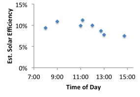 | Figure 4. (Solar efficiency vs. time): For reference, the OEM solar-panel efficiency rating is 13.6% |
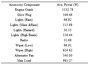
For the purpose of assessing the overall effectiveness of the VIPV system, we will assume an average daily solar insolation of 4 kWh/m2[6]. Considering the OEM-rated solar-panel efficiency of 13.6% then gives a possible solar-panel output of 544 Wh/m2-day, on average. The totaldaily energy available from a vehicle-mounted PV system depends on theproportionally on the available area of the rooftop or appropriate PV panel. The PV panel used in our studyhas an area of 1.32m2and can thus produce approximately 718 Wh/day (2.585 MJ/day). Therefore,with anaverage efficiency of 84.0% for the charge-controller used in our study(calculated from measured input and output voltage and current) the average solar -to-battery energy -conversion efficiency is then 11.7%, and the total available energy available for supporting auxiliary loads or battery chargingis approximately 601.9 Wh. This valuewill be used to determine the limitations of the alternator-lessapproach in our scenario-based analysis.The Motorola alternator in our test vehicle outputs 65A at 14V and produces a peak power of 910W[9]. At an alternator efficiency of 21% [1] the peak fuel-derived power taken from the engine is approximately 4333 W. This fuel energy is recoverable through the implementation of a solar electrical system by permitting the alternator to freely spin. However, from a consumer perspective, the availability of an alternator permits usage of any “comfort feature” as long as there is fuel energy available without hindrance due to reduced energy availability. Dynamometer testing explores the upper limit achievable from alternator-less operation as an alternative to alternator-based charging.The measured starter power required for our test vehicle was less than the manufacturer’s listed specification, while continuous glow-plug power was found to be higher than rated[9]. Table 2 summarizes the measured average power requirements for each accessory load tested. These values are used in the scenario-based analysis to determine the limitations of the PV charging system in daily operating conditions.Table 2. Accessory Power Requirements
 |
| |
|
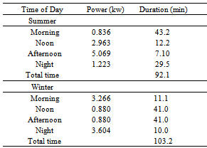
The accessory-load test scenariosoutlined in Table 1 involve different accessory-load combinations and total power requirements. The average daily PV energy of approximately 601.9 Wh availablefromthe roof-mounted solar panel was used to determine the total number of hours of operation possibleunder each scenario.To this end, the daily available PV energy is divided equally between the four trip componentsof each scenario. The results are summarized in Table 3. The operating times vary dependingon time of year andenvironmental conditions. The engine cooling requirements during midday summer operation limit the range of the alternator-less mode. Winter morning and night interior-heating requirements also dampen the benefits of this approach.During testing, it was occasionally found that alternator energy was insufficient for powering all of the accessory loads and that battery energy was required. Operation in this regime decreases battery longevity, if maintained for long periods of time, and may result in sulfation. This reveals one of the limitations of theVIPV system as the sole source of electrical energy. Therefore, for night-driving scenarios and battery longevity an alternator should be present, in case photovoltaic or battery energy is insufficient for supporting auxiliary loads. Alternatively, the limitations of the alternator-less vehicle might be mitigated by the integration of supplementary electrical energy, for example through regenerative braking or an emergency clutched alternator.Table 3. Accessory Power Usage
 |
| |
|
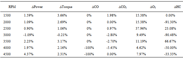
The SAE J1667 opacity test confirmed lower average opacity, indicating reducede missions of particulate matter,with the alternator-less mode of vehicle operation. Specifically, the opacity was found to decrease by 56.76%, on average. Similar results were observed during dynamometer testing. The change in engine power, torque and emissions associated with alternator-less operation as a percentage of the respective baseline values(associated with alternator-based charging)are summarized in Table 4. Under part-load (step) dynamometer testing, average HC and CO2 emissions decreased on average 25.05% and 1.14%, respectively, while the average power (torque) increased by 1.57% (2.12%). Peak power and torque could not be measured through full-load (sweep) dynamometer testing for the completely alternator-less mode due to cooling issues correlated to insufficient battery state of charge. This observation during testing is consistent with the limitations of the scenario-based analysis discussed earlier.Full-load dynamometer testsconducted for the alternator -less and baselineconfigurationsrevealed that the alternator produces a load even when not charging the energy storage device, for examplewith the alternator connection to the battery disabled, and when no pilot excitation is active. The engine torque was found to increase with increasing engine speed in both configurations. Greater engine torque was found for the alternator-less configuration at engine speeds below about 2200 RPM, while no noticeable difference in torque for the two configurations was found at higher engine speeds. The finding of increasing engine torque with engine speed without thepresence of an accessory load can be explained by the resistive losses within the alternator becoming more significant as engine speed increases due an electromagnetic load generated by the stator coils and rotor moving past one another, even in the absence of an electrical load.
4. Conclusions
The application of a photovoltaic charging system for reducing alternator auxiliary loads on a compression-ignition Engine has been explored in this study. Evaluation of the PV panel mounted atop of our test vehicle its ancillary electrical components revealed anaverage solar-to-battery energy -conversion efficiency of 11.7%, accounting for the solar -panel OEM-rated conversion efficiency of 13.6%.In full-load dynamometer testing, the alternator-based charging systemwas found to exact auxiliary loads onour test engine even when no pilot excitation or accessory electrical loads were present. Notwithstanding this, the VIPV systemcan be effective in reducing electrical loads on the engine at low engine speeds when an alternator is present and at all engine speeds in the absence of an alternator. Soot opacity and hydrocarbon emissions were reduced by alternator-less operation of the test vehicle. We found a reduction of soot opacity by 56.76%, inferring significant reductions in PM emissions as well. The part-load step tests showed average decreases in HC and CO2 emissions of 25.05% and 1.14%, respectively. These emissions reductions for the alternator-less operation modeare noteworthydespite its limitation in the midday-summer and winter-night scenarios that were considered.The part-load test indicated an average increase in part-load power (1.57%) and torque (2.12%) as well.Table 4. Vipv Engine Performance & Emissions
 |
| |
|
In summary, VIPV alternator-less operation offers an alternative to traditional enhancements for emissions reduction and performance improvement. Although this mode of operation may result in performance and emissions improvements, limitations are revealed in user-oriented, scenario-based analyses. The midday -summer and winter -night scenarios considered in our studyhighlight a particular limitationofthe VIPV electrical system associated with a limitation of the maximum exposed solar-panel area to the vehicle-roof area. However, this limitation can be mitigated through the use of theVIPV system as a complement to the production of electricity by the alternator.
ACKNOWLEDGEMENTS
We are grateful to Dr. Andrew Burke forassistance with testing during the study.
References
| [1] | M. Bradfield, "Improving Alternator Efficiency Measurably Reduces Fuel Costs," Remy, Inc., 2008, pp. 1-31. |
| [2] | M. Fujinaka, “Solar cars free of environmental pollution—prototype of practically usable car completed,” Renewable energy, vol. 2, no. 1, pp. 57-64, 1992. |
| [3] | J. Haringman, “Solar Team Twente documentary “Desert of no time”,” Solar Racing News, September 30, 2012. |
| [4] | D. Pile, “Photovoltaics: Solar -assisted cars,” Nature Photonics, vol. 3, no. 4, pp. 195-195, 2009. |
| [5] | I. Buchmann, Batteries in a portable world: Cadex Electronics Richmond, 2001. |
| [6] | F. M. Vanek, and L. D. Albright, Energy systems engineering: McGraw-Hill, 2008. |
| [7] | US Navy Solar Angle Calculator; http:// aa.usno. navy. mil/data/docs/AltAz.php. |
| [8] | The Weather Channel; http://weather.com. |
| [9] | B. Publishers, and i. Robert Bentley, Volkswagen Rabbit/Jetta diesel service manual, including pickup truck and turbo-diesel, 1977, 1978, 1979, 1980, 1981, 1982, 1983, 1984: Bentley Pub, 1984 |
 Abstract
 Reference
 Full-Text PDF
 Full-text HTML