-
Paper Information
- Previous Paper
- Paper Submission
-
Journal Information
- About This Journal
- Editorial Board
- Current Issue
- Archive
- Author Guidelines
- Contact Us
Energy and Power
p-ISSN: 2163-159X e-ISSN: 2163-1603
2013; 3(2): 18-25
doi:10.5923/j.ep.20130302.02
Vector Control Analysis of Doubly-Fed Induction Generator in Wind Farms
 Abstract
 Reference
 Full-Text PDF
 Full-text HTML
Hassan Abniki1, Mahmood Abolhasani2, Mohammad Ehsan Kargahi1
1ECE School, University of Tehran, Tehran, Iran
2Faculty of Environment and Energy, Science and research branch Islamic Azad University, Tehran, Iran
Correspondence to: Hassan Abniki, ECE School, University of Tehran, Tehran, Iran.
| Email: |  |
Copyright © 2012 Scientific & Academic Publishing. All Rights Reserved.
This paper presents vector control of grid-connected wind turbines; also the second goal of this research is to survey the vector control for wind turbines with doubly-fed induction generators (DFIGs) when a short circuit faults in grid happens. In fact in this paper, vector control of stator-flux is applied for stator- and rotor-side converters in order to control of active and reactive powers simultaneously, and to keep the DC-link voltage constant. Also the method performances are tested in different cases.
Keywords: Vector Control, Wind Turbine, DFIG, Inverter
Cite this paper: Hassan Abniki, Mahmood Abolhasani, Mohammad Ehsan Kargahi, Vector Control Analysis of Doubly-Fed Induction Generator in Wind Farms, Energy and Power, Vol. 3 No. 2, 2013, pp. 18-25. doi: 10.5923/j.ep.20130302.02.
1. Introduction
- Nowadays, DFIGs are used by the industry for larger wind turbines[1]. The small size of power converter, a cost efficient solution in order to obtain variable speed is one reason to increase DFIG uses more[2]. Many DFIG models are modeled in many papers[3-8], such as the full-model which is a 5th order model. Also in[6], the 3rd order model of DFIG is presented that uses a rotor current. By disregarding the stator flux linkage variations and given rotor voltage, the 3rd order model can be obtained[7-9]. Additionally, in order to model back-to-back converters in the simplest scenario, the converters are ideal and we have a constant DC-link voltage between the converters[7-13]. Therefore, a controllable voltage (current) source can be implemented, considering the converter control. Other similar papers are studied in[14-17]. However, while increasing during the fault condition, DC link voltage is not continuous. So, it is not possible to determine that the DFIG will mal-trip after a fault or not. However, as a hysteresis controller method it has two main disadvantages: non constant switching frequency while varying along the AC current; and secondly due to the severity and fortuitousness of the operation, the converter protection is troublesome[18]. A variable structure control (VSC) method for a DIFG is presented in[19], using the principles of an reactive and active power controller known as modified DPC and where VSC and space-vector modulation are combined to ensure better operation. The VSC technique is designed which provides robust power controls without frame transformation and the current controller that in the common control drive is used. In[20], a simulation model consisting of two DFIGs connected to IEEE 34-bus test for two vector control based method was set up to investigate the transient performance of the micro grid. Then, different types of faults of the DFIGs were analyzed through the simulation model by using vector control strategy. Also[21] focuses on the decoupled control of active and reactive power for variable speed constant frequency wind generation system and principle of maximum wind power tracking for wind generation system is analyzed. Also an effective method of independent active power and reactive power control is proposed. In[22] some control designs for a variable-speed constant-frequency wind energy system is presented using DFIG. This paper aim is to develop a nonlinear vector control technique using the second Lyapunov approach for the rotor side converter, and a network voltage vector control of the grid side converter, and to maximize the energy of the wind turbine and injected to the grid. In[23], the d-q model of the induction generator is developed from the fundamentals in a modular approach in Simulink and a fuzzy logic controller is designed for indirect vector control of induction generator. To provide a direct axis current reference Id, which controls the motor flux, the speed control loop uses a fuzzy logic controller. The motor torque is controlled by Quad rature axis current reference Id. Also in[24], a vector control technique is studied to control the rotor side voltage that allows the active and reactive power be controlled as well as the rotor speed in order to get the maximum wind power point. In fact a Neuro-fuzzy gain tuner is proposed to control the DFIG. Each Neuro-fuzzy system input is the generator speed error value, and active or reactive power. The choice of only one input simplifies the design of the system.Under fault condition the DFIGs vector control is more significance. To resolve the problems, this paper proposes a DFIG vector control whereas sinusoidal PWM (SPWM) is applied to maintain the switching frequency constant. To get constant switching frequency, calculation of the required rotor voltage that must be supplied to the generator is adopted. The results show the appropriate performance of the presented method in all conditions.
2. Methodology
- Nowadays variable speed wind methods have recently become very popular as generators. A more general scheme of the DFIG system with back-to-back converter is presented in[14] as shown in Fig. 1.
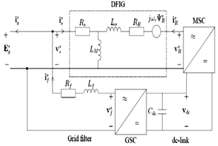 | Figure 1. Equivalent circuit of the DFIG[14] |
 | (1) |
 | (2) |
 | (3) |
 | (4) |
 | (5) |
 | (6) |
 | (7) |
 | (8) |
 | (9) |
 | (10) |
 | (11) |
 | (12) |
 | (13) |
 | (14) |
 | (15) |
 | (16) |
 | (17) |
 | (18) |
 | (19) |
 | (20) |
 | (21) |
 | (22) |
 | (23) |
 | (24) |
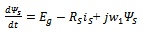
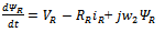
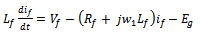
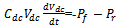
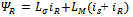
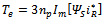
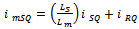
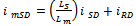
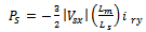
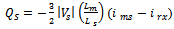
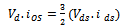
 can be obtained either from an outer speed control loop or from a reference torque imposed on the machine. The flow of real and reactive power is controlled by the grid-side converter, through the grid interfacing inductance. The objective of the grid-side converter is to keep the dc-link voltage constant regardless of the magnitude and direction of the rotor power. The vector control method is used as well, enabling independent control of the active and reactive power flowing between the grid and the converter. The PWM converter with the d-axis current used to regulate the dc-link voltage and the q-axis current component to regulate the reactive power. Fig. 2(b) shows the schematic control structure of the grid-side converter. Whole equations are available in[25] and also the abbreviations are as following:
 Voltage, current and flux vectorsRs, Rr Stator, rotor winding resistancesLs, Lr, Lls, Llr Stator, rotor winding self- and leakage inductancesLm Magnetizing inductance
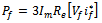
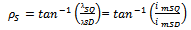
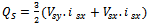
 Synchronous, rotor, slip angular frequencyP, Q Active and reactive powers, r Stator and rotor subscriptsg Grid-side value subscriptsc Converter value subscriptsd, q d-axis and q-axis component subscriptsn Nominal value subscriptref Reference value superscriptRegarding the equations in[15], and after a couple of other calculations, we have:
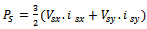 | (25) |
 | (26) |
 | (27) |
 | (28) |
 | (29) |
 | (30) |
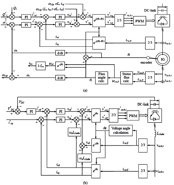 | Figure 2. a) Vector control structure for rotor-side converter, b) Vector control scheme for grid-side converter[25] |
 | (31) |
 | (32) |
3. Simulated Network
- The stator of the wound rotor induction machine is connected to the low voltage balanced three phase grid and the rotor side is fed via the back-to-back IGBT voltage source inverters with a DC bus. the power flow is controlled by the front–end converter between the DC bus and the AC side and allows the system to be operated in sub-synchronous and super synchronous speed. Fig. 3 shows schematic of DFIG for wind turbine application and also Fig. 4 shows the schematic structure of DFIG application for the wind turbine simulated in PSCAD/EMTDC. In fact, DFIG is basically a standard rotor-wounded induction machine in which stator is directly connected to the grid. It can be said that converter has two parts: rotor-side, and grid-side. Rotor-side converter acts as a voltage source one, while the grid-side convertor is expected to keep the capacitor voltage under wind speed changes and different conditions of grid (Figs. 3 and 4).
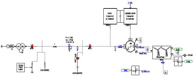 | Figure 3. Schematic of simulated system by PSCAD/EMTDC |
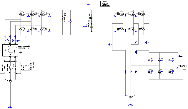 | Figure 4. Schematic structure of inverter and rectifier simulated in PSCAD/EMTDC |
4. Results
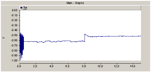
- The control scheme of the PSCAD/EMTDC simulated study case for a wind turbine utilizing DFIG was shown in previous section. The stator and rotor current waveforms of the induction generator are shown in Fig. 5. The case is set up to track for maximum wind power utilization. The 'power coefficient', Cp is a function of wind speed/machine speed. As wind speed a change, machine speed is changed to operate at maximum Cp , P and Q can be independently controlled irrespective of the machine slip (speed). Determining the relative difference between stator flux and rotor position is done for resolving the rotor currents. In all simulations, after 0.5 seconds, the control torque is applied. It is observed after 8th second, with a step change in speed, the flow rate have been retrieved. Also, in this paper using a filter, the stator flux dc component is removed. In Fig. 6, differences betrween stator and rotor flux of DFIG is shown. Also, Fig. 7 shows active and reactive and reference speed of DFIG. At time 8 sec, the reference speed changed and consequently the estimated speed changes. Also, active and reactive power changes whereas vector control do well this work as soon as possible in order to get maximum torque. Turbine speed and this difference are clearly seen in this view. The capacitor of dc link can be charged to amount of the charge. These capacitors are usually a great value. Diagram and the output converter voltage obtained are as following active and reactive power output of the reference speed and DFIG rotor speed that can be seen in the Fig. 8. In this Fig, after appliying verctor control at time 1 sec, some varions are inevitabe and after that maximum torque is reseulted. In Fig. 9 at time 3 sec, a fault was clearced while vector control was existed; so the variations are very little. Switching to torque control situation after 0.5 sec is done and untill this time, the machine rotate at a selected speed/sec as specified at the input W. This value is used as the initial speed. If a turbine start up is under investigation, then the initial value will have to be changed accordingly. Although, a step change in wind speed at the specified instant, this would cause the speed controller to react and maintain the tip speed ration for maximum power. In this regard, the optimal tip speed ration should be known and can be derived from the turbine torque equations.
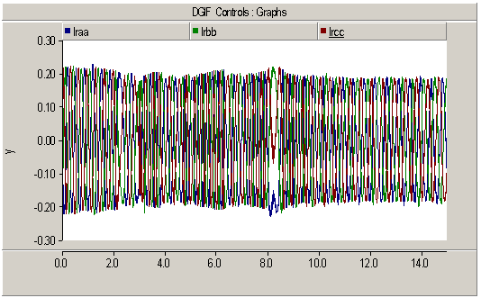 | Figure 5. Turbine rotor current during speed variation |
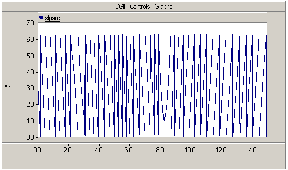 | Figure 6. Differences betrween stator and rotor flux |
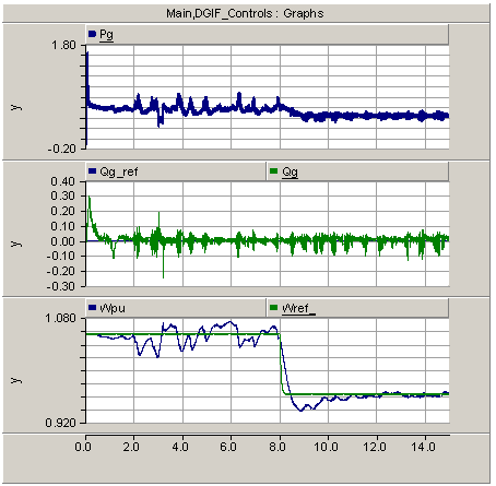 | Figure 7. Active and reactive and referecne speed of DFIG |
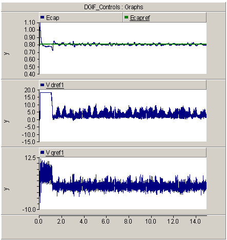 | Figure 8. Reference voltage ouptputs for d and q axis of DFIG |
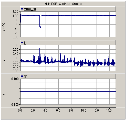 | Figure 9. DFIG rotor current and voltage (rms) of DFIG |
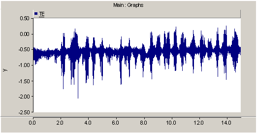 | Figure 10. Electrical torque of DFIG |
 | Figure 11. Mechanical torque of DFIG |
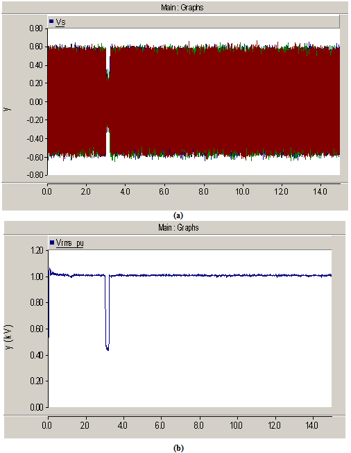 | Figure 12. a) The value of produced voltage for all phases, b) The rms value of produced voltage |
5. Conclusions
- In this paper, a doubly fed induction generator as the power conversion system in wind turbines is analysed by vector controlled for better control of the grid while injecting the required active power of the system. The system model is developed in the dedicated power electronics and system simulation tool, EMTDC software. The model includes wind speed fluctuations, enabling simulation of the power quality characteristics of the wind turbine. Based on results, the proposed vector control of DFIG is capable of simultaneous capturing maximum power of wind energy with fluctuating wind speed and improving power quality, and this is achieved by cancelling the most significant and troublesome harmonics of the utility grid by vector control. Reactive and active power controls are the other two significant features of the proposed technology. Also, vector control of DFIG wind turbines is investigated after the clearance of short circuit faults in grid.