Bello R., Obawole A. Kenneth
Department of Physics Federal University of Agriculture, Abeokuta, Nigeria
Correspondence to: Bello R., Department of Physics Federal University of Agriculture, Abeokuta, Nigeria.
| Email: |  |
Copyright © 2012 Scientific & Academic Publishing. All Rights Reserved.
Abstract
This work is based on the study of the General principles of Thermocouple and how it is used for measuring voltage outputs in which two wires of different metals are joined together. The wires of dissimilar metals that were used in this study were Copper and the Constantan wires.This work investigated the effect of temperature on the thermoelectric properties of these wires (Copper and Constantan Wires). The work involved the use of two numbers five liters and two numbers ten liters containers for the cold and hot junctions. It was observed that an increase in the temperature of the hot junction led to an increase in the output voltage and vice versa. Also the more the difference in temperature between the hot and cold junction, the more the output voltage. It was also observed that the volume of containers of the hot and cold junctions has effect on the output voltage. The maximum voltage recorded in the ten liters containers was 4.100mV while the maximum voltage recorded in the five liters container was 3.500mV.
Keywords:
Thermocouple, Temperature, Copper, Constantan, Junction
Cite this paper: Bello R., Obawole A. Kenneth, Effect of Temperature on Thermoelectric Properties of Copper and Constatan Wires, Energy and Power, Vol. 3 No. 2, 2013, pp. 13-17. doi: 10.5923/j.ep.20130302.01.
1. Introduction
A Thermocouple is a device used for measuring temperature in which two wires of different metals are joined. The basis of thermocouples was established by Thomas Johann Seebeck in 1821 when he discovered that a conductor generates a voltage when subjected to a temperature gradient[1]. The potential difference between the wires is a measure of the temperature of the temperature difference between the two junctions. The different wires of different metals are joined at each end. When these two junctions are kept at different temperatures, a small electric current is induced. Due to the flow of current, a voltage drop occurs. The voltage drop depends on the temperature difference between the two junctions. The measurement of the voltage drop can then be correlated to this temperature difference. It is extremely important to note that a thermocouple does not measure the temperature, but rather the temperature difference between the two junctions[2]. In order to use thermocouple to measure the temperature directly, one junction must be maintained at a known temperature. This junction is commonly used and called the Reference Junction, and its temperature is called the Reference Temperature. The other junction which is normally placed in contact with the body of unknown temperature is called the measurement junction. Also, the joined end is referred to as the Hot junction, the other end of these dissimilar metals is referred to as the End or Cold Junction. The cold junction is usually formed at the last point of thermocouple material. The voltage created by a thermocouple is extremely small and is measured in millivolt. Thermocouple can be used in measurement of Temperature very accurately where small voltage of different or dissimilar metals are joined to form a loop and the two wires are of different temperatures. Thermocouples are also suitable for measuring over a large temperature range, up to 2300◦C. They are less suitable for applications where smaller temperature differences need to be measured with high accuracy. Thermocouple is practically used for different measurement such as Voltage-Temperature relationship, cold junction compensation etc[3]. This research work investigated the various factors that could affect the output voltage and efficiency of a thermocouple. These factors included the volume of the containers and the temperature difference between the hot and cold junctions.
2. Applications of Thermocouple
Thermocouples are suitable for measuring over a large temperature range, up to 2300℃. They are less suitable for applications where smaller temperature differences need to be measured with high accuracy, for example, the range 0 ‒100℃ with 0.1℃ accuracy. For such applications, thermistors and resistance temperature detectors are more suitable. Applications include temperature for kilns, gas turbine exhaust, diesel engines, and other industrial processes[4]. Thermocouple are the best options when the need is to measure range of temperature but the efficiency of the device decreases as and how it is used to measure smaller differences in temperature. They are generally used in the steel industry where it is used to measure temperature throughout the entire process of making steel. It is also used in Radioisotope thermoelectric generators to generate electricity, through in a series which is commonly termed as Thermopile[5]Thermocouples are largely used in the fields of science and electronics as a temperature sensor, which are quite easy to handle and use. The functioning of a thermocouple is based on the seeback effect that is common in case of electrical conductors that experience a temperature gradient along their length. These sensors are “simple”, rugged and do not need batteries and have the ability to measure very wide temperature ranges. Thermocouples consist of two different metals, joined together at one end. Whenever the junction of the two metals is heated or cooled a voltage can be obtained that is proportional and can be correlated to the temperature that was given when the sensor was heated. Thermocouple alloys are usually available as wire. They are quite cheap but their main drawback is their accuracy[6].
3. Advantages of Thermocouple over other Methods
Thermocouples are the world’s most popular Temperature sensor. They are widely available, standardized, reasonably cheap and able to measure Extreme Temperatures. They are also capable of producing an electrical signal that has a fairly direct relationship with temperature, a requirement that was particularly critical in early temperature measurement instrumentation. Perhaps this is one reason the use of thermocouples has been so ingrained in the process and manufacturing Industries. Thermocouple is of higher advantage over other methods of temperature measurement because it is also suitable for measuring over a large temperature range of up to 2300 ◦C[7]. Most practical temperature ranges, from cryogenics to jet‒ engine exhaust, can be served using thermocouples. Depending on the metal wires used, a thermocouple is capable of measuring temperature in the range of –200℃ to +2500℃. Thermocouples are rugged devices that are immune to shock and vibration and are suitable for use in hazardous environments. Because they are small and have low thermal capacity, thermocouples respond rapidly to temperature changes, especially if the sensing junction is exposed. They can respond to rapidly changing temperatures within few hundred milliseconds. They are not prone to self-heating and are intrinsically safe because thermocouples require no excitation power.
4. Types of Thermocouple
Certain combinations of alloys have become popular as industry standards. Selection of the combination is driven by cost, availability, convenience, melting point, chemical properties, stability, and output. Different types are best suited for different applications. They are usually selected based on the temperature range and sensitivity needed. Thermocouples with low sensitivities (B, R, and S types) have correspondingly lower resolutions[8]. Other selection criteria include the inertness of the thermocouple materials and whether it is magnetic or not. Standard thermocouple types are listed below with the positive electrode first, followed by the negative electrode.
4.1. K Type Thermocouple
Type K (chromel /alumel) is the most common general purpose thermocouple. It has a sensitivity of approximately 41µV/℃, chromel is positive related to alumel. It is cheap, and wide variety of probes are available in its ‒200℃ to +1350℃ range, Type K was specified at a time when metallurgy was less advanced than it is today, and consequently characteristics vary considerably between samples. One of the constituent metals, nickel, is magnetic, a characteristics of thermocouple made with magnetic material is that they undergo a step change in output when the magnetic material reaches its curie point (around 354℃ for type K thermocouple).
4.2. E Type Thermocouple
Type E (chromel /constatan) has a high output (68µV /℃) which makes it well suited to cryogenic use. Additionally, it is non–magnetic.
4.3. J Type Thermocouple
Type J (Iron–consantan) has a more restricted range than type K(–40 to +750), but higher sensitivity of about 55µV ̸℃. The curie point of the iron(770℃) causes an abrupt change in the characteristic, which determines the upper temperature limit.
4.4. N Type Thermocouple
Type N (Nicosil‒ Nisil ) (Nickel‒ Chromium ‒ silicon /̸ Nickel– Silicon) thermocouples are suitable for use at high temperatures, exceeding 1200℃, due to their stability and ability to resist high temperature oxidation. Sensitivity is about 39µV ̸℃ at 900℃, slightly lower than type K. It is designed to be an improved type K, it is becoming more popular.
4.5. Platinum Types B, R and S
Types B, R, and S thermocouples use platinum‒rhodium alloy for each conductor. These are among the most stable thermocouples, but have lower sensitivity than other types, approximately 10µV ̸℃. Types B, R and S thermocouples are usually used only for high temperature measurement s due to their high cost and low sensitivity.Type B thermocouples use a platinum–rhodium alloy for each conductor. One conductor contains 30% rhodium while the other conductor contains 6% rhodium. These thermocouples are suited for use at up to 1800℃. Type B thermocouples produce the same output at 0℃ and 42℃, limiting their use below 50℃.Type R thermocouples use Platinum–rhodium alloy containing 13% rhodium for one conductor and pure platinum for the other conductor. Types R thermocouples are used up to 1600℃.The type S thermocouples are constructed using one wire 90% platinum and 10% rhodium(positive or“ + ” wire) and a second wire of 100% platinum (the negative“ – ”). Like the type R, Type S thermocouples are used up to 1600℃. In particular, type S is used as the standard of calibration for the melting point of gold (1064.43℃).Type T (copper‒ constantan) thermocouples are suited for measurements in the ‒200 to 350℃ range. Often used as a differential measurement since only copper wire touches the probes. Since both conductors and non‒magnetic, there is no curie point and thus no abrupt change in characteristics. Type T thermocouples have a sensitivity of about 43 µV /℃.Type C (tungsten 5% rhenium – tungsten 26% rhenium) thermocouples are suited for measurements in the 0℃ to 2320℃ range. This thermocouple is well – suited for vacuum furnaces at extremely high temperatures. It must never be used in presence of oxygen at temperatures above 260℃.Type M thermocouples use a nickel alloy for each wire. The positive wire contains 18% molybdenum while the negative wire contains 0.8% colbalt. These thermocouples are used in vacuum furnaces for the same reasons as with type C. Upper temperature is limited to 1400℃. It is less commonly used than other types.
4.6. Chromel Gold / Iron
In chromel-gold/iron thermocouples, the positive wire is chromel and the negative wire is gold with a small fraction (0.03-0.15atom percent) of iron. It can be used for Cryogenic applications (1.2-300k and even up to 600k). Both the resistivity and the temperature range depends on the iron concentration. The sensitivity is typically around 15µV/K at low temperatures and the lowest usable temperature varies between 1.2 and 4.2k[9].
5. Methodology
The first experiment involved the use of 5 liters containers for both the cold and hot junctions, while the second experiment involved the use of 10 liters containers for both the cold and hot junctions. The total length of the copper / constantan wire is two feet. The experiment was in two parts, the first part involved keeping the temperature of the hot junction constant while changing the temperature of the cold junction while the second part involved keeping the temperature of the cold junction constant while changing the temperature of the hot junction.
6. Results and Discussions
6.1. Keeping the Temperature of the Cold Junction at 0℃ while Changing the Temperature of the Hot Junction in the 5 Liters Containers
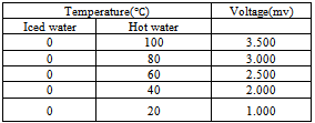
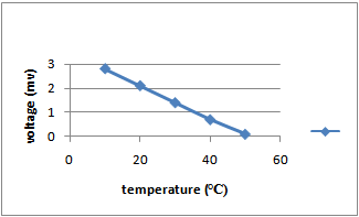
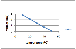
The temperature of the cold junction was maintained at 0℃ throughout this experiment while the temperature of the hot junction was initially 100℃. The voltages at the voltmeter were recorded as the temperature of the hot junction dropped from 100℃ to 20℃ in steps of 2℃. The values of the voltages recorded also decrease in equal proportion to the decrease in temperature of the hot junction. This is presented in Table 1 and graphically in figure 1. The graph of the plot of voltages (mV) against the temperature (℃) showed a linear graph which can be represented as where y is the measured voltage in mV andx = Temperature of Hot junction in ℃.This showed that an increase in temperature of the hot junction led to an increase in the output voltage and a decrease in temperature of the hot junction led to a decrease in the output voltage.
Table 1. The voltages (mV) obtained when keeping the temperature of the cold junction at 0℃ while changing the temperature of the hot junction in the 5 liters container
 |
| |
|
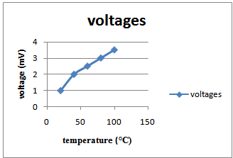 | Figure 1. Voltage / Temperature for copper/ constantan thermocouples with cold junction temperature kept at 0℃ |
6.2. Keeping the Temperature of the Hot Junction at 100℃ while increasing the Temperature of the Cold Junction in the 5 Liters Container
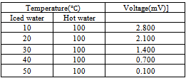
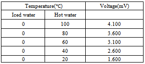
The temperature of the hot junction was kept constant at 100℃ throughout the experiment while the temperature of the cold junction was increased in step of 10℃. The aim of this experiment is to demonstrate that the more the difference between the temperature of the cold and hot junctions, the more the voltage generated.The result is presented in Table 2 and presented graphically in figure 2.It could be seen from Table 2 that an increase in the temperature of the cold junction led to a decrease in the output voltage. Figure 2 shows a straight line graph with a negative slope and can be represented by.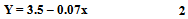 Where Y is the measured voltage in mV andX is the temperature of the iced junction in ℃The results of this experiment showed that the more the difference in temperature between the cold and hot junctions, the more the output voltage. Hence, in order to get the maximum voltage from thermocouple, the two junctions must be maintained at two extreme temperatures.
Table 2. The voltages (mV) obtained when keeping the temperature of the hot junction at 100℃ while increasing the temperature of the cold junction in the 5 liters container
 |
| |
|
 | Figure 2. Voltage/Temperature for copper/constantan thermocouple with hot junction constant at 100℃ |
6.3. Keeping the Temperature of the Cold Junction at 0℃ while increasing the Temperature of the Hot Junction in the 10 Liters Containers
The temperature of the cold junction was maintained at 0℃ throughout this experiment while the temperature of the hot junction was initially 100℃. The voltages at the voltmeter were recorded as the temperature of the hot junction dropped from 100℃ to 20℃ in step of 20℃. The values of voltages recorded also decrease in equal proportion to the decrease in temperature of the hot junction. This is presented in Table 3 and graphically in figure 3. The graph of the plot of voltages (mV) against the temperature (℃) gives a straight line graph which can be represented as Where y is the measured Voltage in mV andx = Temperature of the hot junction in ℃This showed that an increase in temperature of the hot junction led to an increase in the output voltage and vice versa. Also the maximum temperature recorded was more than the maximum temperature recorded in the 5 liters experiment. This showed that the volume of the containers had effect on the output voltage.
Table 3. The voltages (mV) when keeping the temperature of the cold junction at 0℃ while increasing the temperature of the cold junction in the 10 liters containers
 |
| |
|
 | Figure 3. Voltage/ Temperature for copper/constantan thermocouples with cold junction kept constant at 0℃ |
6.4. Keeping the Temperature of the Hot Junction at 100℃ while increasing the Temperature of the Cold Junction in the 10 Liters Containers
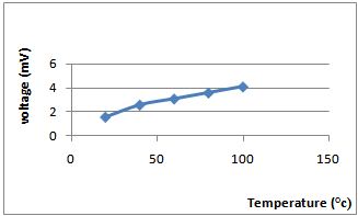
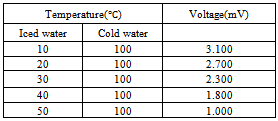
The temperature of the hot junction was kept constant at 100℃ throughout the experiment while the temperature of the cold junction was increased in step of 10℃. The aim of this experiment is to demonstrate that the more the difference between the temperature of the cold and hot junctions, the more the voltage generated.The result is presented in Table 4, it showed that an increase in the temperature of the cold junction led to a decrease in the output voltage. Figure 4 showed the graph with a negative slope and it can be represented as Where Y is the measured voltage in mV andX is the temperature of the cold junction in ℃. The results of this experiment showed that the more the difference in temperature between the cold and hot junctions, the more the output voltage. Hence, in order to get the maximum voltages from thermocouple, the two junctions must be maintained at two extreme temperatures.
Table 4. The voltage obtained when keeping the temperature of the hot junction at 100℃ while increasing the temperature of the cold junction in the 10 liters containers
 |
| |
|
 | Figure 4. Voltage/ temperature for copper/constantan thermocouples with hot junction temperature at 100℃ |
7. Conclusions
The aim of this experiment was to demonstrate the effect of temperature and volume of containers on the thermoelectric properties of copper and constantan wires. The results of the experiment showed that the temperature of the hot and cold junctions had effect on the thermoelectric properties of Copper and Constantan wires. Keeping the temperature of the cold junction at 0℃ while changing the temperature at the hot junction in both the 5 and 10 liters containers, the graphs of the voltage (mV) against temperature (℃) gave a positive linear graph which implies an increase in temperature of the hot junction led to an increase in the output voltage and vice versa.Keeping the temperature of the hot junction at 100℃ while increasing the temperature of the cold junction in both the 5 and 10 liters containers, the graphs of the voltage (mV) against temperature (℃) gave a negative linear graph which implies that an increase in temperature of the cold junction led to a decrease in the output voltage and vice versa.Also the volume of containers of the cold and hot junctions had effect on the output voltage as the maximum voltage of the 10 liters container was more than that of the 5 liters containers.This work therefore showed that the more the difference in the temperature of the two junctions in a thermocouple, the more the output voltage. Also, volume of containers holding the hot and cold junctions had effect on the output voltage.
References
| [1] | National Instrument, (2011) Temperature Measurements with Thermocouples: How-To Guild Available at: http://www.technologyreview.com/files/81302.../pdf. |
| [2] | Mathew Duff and Joseph Towey, (2010) Two ways to measure Temperature using Thermocouples Features Simplicity, Accuracy, and Flexibility. Analog Dialogue, Vol. 44. Available at:http://www.analog.com/library/analogDialigue/archieves/44-10/thermocouple.html. |
| [3] | Dan K, (2010) What are Thermocouples? Private Communication. Available at: www.vacaero.com. |
| [4] | Dataq, (2000) Thermocouple Application. Available at: www.picotech.com/applications/thermocouples. |
| [5] | Buzzle, (2001) Thermocouple: Know More about Thermocouples, Their Functions and Uses. Available at: http://www.buzzle.com/articles/thermocouple.html. |
| [6] | ASTM, (1981) Use of Thermocouple in temperature measurement. Available at: www.knovel.com |
| [7] | Walt Kester, James Bryant and Walt Jury, (Accessed 2012) Analog Devices: Sensor Signal Conditioning, Temperature Sensors, Chapter 7. Available at:http://www.analog.com/static/imported-files/tutorials/temperature_sensors_chapter7.pdf. |
| [8] | Thermometricscorp, (Accessed 2012) Available Thermocouple Types. Available at:http://www.thermometricscorp.com/available_Thermocouple_Types.html. |
| [9] | Adebayo O.O, (2010). Investigation of power Generation using solar thermocouple. B.Sc. Project, Federal university of Agriculture Abeokuta, Nigeria. pp 11‒12. |
 Abstract
 Reference
 Full-Text PDF
 Full-text HTML