-
Paper Information
- Paper Submission
-
Journal Information
- About This Journal
- Editorial Board
- Current Issue
- Archive
- Author Guidelines
- Contact Us
Energy and Power
p-ISSN: 2163-159X e-ISSN: 2163-1603
2013; 3(1): 1-6
doi:10.5923/j.ep.20130301.01
Cost Effective, Low Capacity, Biomass Fired Power Plant
 Abstract
 Reference
 Full-Text PDF
 Full-text HTML
Rajaram Swaminathan
Department of Mechanical Engineering, Polytechnic of Namibia, Windhoek, Namibia
Correspondence to: Rajaram Swaminathan , Department of Mechanical Engineering, Polytechnic of Namibia, Windhoek, Namibia.
| Email: |  |
Copyright © 2012 Scientific & Academic Publishing. All Rights Reserved.
In view of the growing energy scarcity in rural areas of developing economies, it is necessary to explore alternate means of electric power generation. In this context distributed power generation becomes significant. Stirling engine based system is an attractive option for distributed power generation. Biomass, especially bush waste which is abundantly available in Namibia, can be gainfully used as a fuel for the Stirling engine. Briquetting the bio-mass and firing it externally in a furnace or stove will provide the necessary heat source for the engine. A conventional electric power generator can be coupled to the engine. Units of rating 1-5kW will cater to the power needs of individual or group of dwellings. The expected cost of generation is 0.233 N$/kWh which compares well with other modes of power generation. This paper explains the basic concepts and the design aspects of biomass fired Stirling engine system.
Keywords: Stirling Engine Based, Low Capacity ,Biomass Fired Power Plant
Cite this paper: Rajaram Swaminathan , Cost Effective, Low Capacity, Biomass Fired Power Plant, Energy and Power, Vol. 3 No. 1, 2013, pp. 1-6. doi: 10.5923/j.ep.20130301.01.
Article Outline
1. Introduction
- In view of the growing energy scarcity in rural areas, it is necessary to explore alternate means. In this context distributed power generation becomes significant[1]. Distributed power generation is basically decentralized generation connected to the local distribution network[2]. The locally available energy sources can be used for distributed power generation. In rural areas of Africa biomass is a viable source of energy. Considerable proportions of Namibia’s natural rangelands are encroached by a biomass called invader bush, which presents a unique opportunity for distributed power generation[3].Heat generated by burning the biomass like invader bush can be utilised in a Stirling engine to power a generator. Stirling engine based system is an attractive option for distributed power generation[4]. In a Stirling engine, heat is transferred through the hot-end cylinder walls to a confined working fluid which is then converted to mechanical work via the Stirling thermodynamic cycle. This differs from an internal combustion engine, which relies on the ignition of fuel within the engine cylinder to force the piston down with large amounts of heat rejected in the exhaust gas. In general, Stirling engines have relatively high thermodynamic efficiencies. Because they require only heat, Stirling engines also permit high fuel-flexibility and allow for better control of emissions. Stirling engine is positioned as a potential competitor to other on-site power generation technologies, like IC engine and fuel cells[4].Since the Stirling cycle uses an external heat source, it can be run on whatever is available that makes heat — anything from biomass to solar energy.
2. Stirling Engine Principle
- The Stirling engine is based on a closed cycle, where the working gas (normally pressurised He, H2, N2 or air) alternately is compressed in a cold cylinder volume and expanded in a hot cylinder volume. The heat input from the combustion of fuel is transferred from the outside to the working gas at a high temperature (typically 700°C - 750℃). The heat, which is not converted into work on the shaft, is rejected to the cooling water at 40-85℃.The figure below shows the basic principle of the Stirling cycle[5]. The steps in the diagram are explained below. The shown engine has two pistons in one cylinder, which is the simplest one.
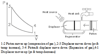 | Figure 1. Stirling engine principle |
3. Stirling Engine Configurations
- Several Stirling engine designs have been developed over the years that employ the basic thermodynamic concept. These Stirling engine designs can be classified by their mechanical configurations. For example, they can have kinematic or free-piston arrangements:Kinematic engines have a crankshaft and a mechanical linkage to the power piston. Electricity is generated with a rotating synchronous induction generator. The amplitude of the power-piston motion is constrained by mechanical linkages. Kinematic machines are generally mechanically complex, but relatively simple to analyze.Free-piston engines typically generate electric power with a linear alternator formed by the oscillatory travel of the power piston in a magnetic field. The displacer and power piston typically move as tuned spring-mass-damper system in response to pressure differences. Free-piston machines are mechanically simple but dynamically andthermodynamically complex. Stirling engines can also have alpha, beta, or gamma arrangements [6] as explained below.Alpha engines have two or more separate pistons mechanically linked to oscillate with constant phase lag. The working gas passes through a cooler, a regenerator, and a heater as it moves back and forth between the cylinders. Each piston requires its own seals to contain the working gas. All alpha engines are kinematic engines. The engine has a very high power-to-volume ratio, but has many technical problems due to the high temperature of the piston and its seals. Beta engines have a displacer-piston arrangement in which the displacer and the power piston are in line with each other(Figure1). The displacer moves the working gas back and forth between the hot and cold ends of the engine. The hot end is the expansion space, and the cold end is the compression space. As the working gas moves back and forth, it passes through a cooler, regenerator, and heater. Beta engines can be either kinematic or free-piston engines. The engine can achieve high compression ratios because the piston and displacer can overlap in motion. Gamma engines have a displacer-piston arrangement where the displacer and power pistons are in separate cylinders. The displacer moves the working gas back and forth between the hot and cold ends of the engine. The cold end space includes the cold side of the displacer as well as the power piston. As the working gas moves back and forth, it passes through a cooler, a regenerator, and a heater. Gamma engines can be either kinematic or free-piston type, however the configuration produces a lower compression ratio.
4. Biomass Fired Stirling Engine
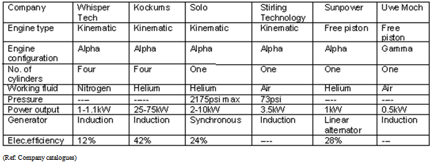
- The following are the key points[7,8,9]:• For bio-mass firing kinematic design is preferred over the free piston design.• Beta configuration is chosen due to its simplicity and high compression ratio.• For improved efficiency regenerator is always included.• Low speed engines are preferred from operation and maintenance point of view.• It is preferable to have both heat and power production to get the maximum benefit• Preferred size for residential combined heat and power is 1-5kWeA typical commercially available bio-mass fired Stirling engine arrangement is given in reference[10]:
4.1. System Concepts
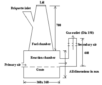
- Direct firing of biomass or firing after gasification of bio-mass are the two basic concepts adopted .Direct firing is preferred since it does not involve multiple equipments and is relatively more maintenance friendly. In both cases, it is advantageous to make briquettes out of bio-mass. This will enable compacting the fuel and storage in minimum space. The briquettes are to be fired in a suitable combustor for giving the needed heat source for the engine(Figure2).The following are some of the concepts for firing the briquettes[11]: i) Furnace firing: In this concept proposed by Helsinki University of Technology[12], the briquettes are fed into the furnace by a screw feeder. Cold primary air and hot secondary air are supplied through separate fans. The heat exchanger for the Stirling engine is located in the furnace. The furnace is equipped with air preheater and water heater. Hot water from the Stirling engine is further heated in the furnace outlet for heat recovery. The system yields hot water and electric power. The scheme is as shown.
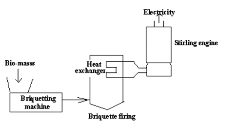 | Figure 2. System concept |
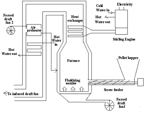 | Figure 3. Furnace firing |
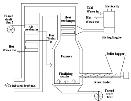 | Figure 4. Fluidized bed firing |
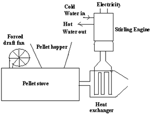 | Figure 5. Pellet fired stove |
 | Figure 6. 4.7Kw Pellet stove |
4.2. Briquetting Machine
- Various designs are available. The preferred type is shown below. It is simple and easy to build[17,18].
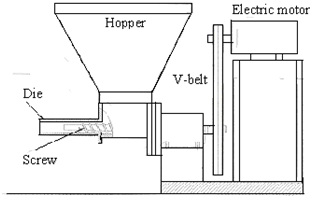 | Figure 7. Mechanised pelletiser |
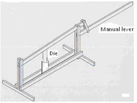 | Figure 8. Manual lever press |
4.3. Stirling Engine
5. Techno-Economic Analysis
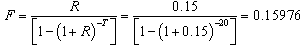
- A techno economic analysis of power plant was made[19,20].The cost per kW of early Stirling engines was around 10000US$/kW. It is expected that as the technology matures, the cost will stabilize at a lower level. The installed cost of a bio-mass fired Stirling engine with auxiliaries is around 2600Euros/kW [21,22].Using 1 kW plant as basis, the estimated investment in Namibian Dollars Estimated Capital cost Euro2600=N$ 28964Est. Installation costs (10% of capital costs)= N$ 2896Estimated Total cost= N$ 31860Est. Operating cost per year (2% of total costs) =N$ 637Levelized Cost Calculation:Capacity factor = 90%Lifetime of plant = 20 yearsAnnual interest rate = 15%Fixed costs FC = N$ 31860/1 = N$ 31860 / kWOperating costs OC = N$ 637/1 = N$ 637 / kWTotal Energy output EO = 7884 hrs/yr*1 kW/yr*20 yrs = 157680 kWhCapital recovery factor=F
 Present value=PV
 Therefore, Levelized cost
 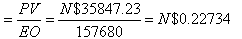 Comparison with Present Electricity tariff (source: Electricity Control Board –ECB)Average cost per unit = N$0.426 / kWhECB levy = N$0.006 / kWhTotal average cost per unit = N$0.432 / kWhAssuming a similar ECB levy, total average levelized cost for biomass power is N$0.23334/kWh (0.22734+0.006).The selling price can be comfortably fixed at N$ 0.432 / kWh (equal to present tariff). Pay back period:Investment cost= N$ 31860Net electricity generation= 1kWHours of operation/year=7884Net electricity generation /year= 7884x1=7884 kWhReturns/year=N$ 7884 x 0.432= N$ 3405Pay back period: Investment cost/Returns per year= 31860/ 7.663= 9.4 yearsIt can thus be concluded that whereas the initial cost of installation for the 1 kW unit is high, in the long run it will payback by itself.
6. Conclusions
- A Beta type kinematic Stirling engine with means for external firing of bio-mass briquettes is a suitable alternative for local distributed power generation. A simple pellet fired home heating stove is adequate for units up to 1kW.For larger size unit furnace firing or fluidized bed firing can be adopted. The installed cost of a typical unit is 31860 N$/kW. The cost of power generation works out to 0.233N$/kWh and the pay back period is less
ACKNOWLEDGEMENTS
- The author thanks the management of the Polytechnic of Namibia for the support and encouragement..