Mohmad Marouf Wani, Mohammad Mursaleen, Saad Parvez
Department of Mechanical Engineering, National Institute of Technology, Srinagar ,J&K ,190006 ,India
Correspondence to: Mohmad Marouf Wani, Department of Mechanical Engineering, National Institute of Technology, Srinagar ,J&K ,190006 ,India.
| Email: |  |
Copyright © 2012 Scientific & Academic Publishing. All Rights Reserved.
Abstract
This paper reports the computer simulation based theoretical and the test rig based experimental investigations for improving the performance and emission characteristics of a two stroke cycle spark ignition engine. Computer simulation was carried out using a standard software. Models were prepared for the carburettor and gasoline direct injection modes. Using the design and operating data of a standard commercial two stroke cycle spark ignition engine results were generated in the carburettor and gasoline direct injection modes. Different parameters like brake power, BSFC, CO and HC emissions, exhaust and spark plug temperatures, peak cylinder gas pressure and its cyclic variations were studied in the carburettor and GDI modes. There was improvement in engine power and reduction in BSFC in the GDI mode as compared to carburettor mode. The CO and HC emissions were reduced in the GDI mode due to better atomization and reduced scavenging loses.
Keywords:
Two Stroke, Engine, Direct Injection, Combustion, Emissions, Performance
Cite this paper: Mohmad Marouf Wani, Mohammad Mursaleen, Saad Parvez, Investigations on a Two Stroke Cycle Spark Ignition Engine Using Gasoline Direct Injection, Energy and Power, Vol. 2 No. 7, 2012, pp. 116-122. doi: 10.5923/j.ep.20120207.01.
1. Introduction
Mixture preparation in all types of S.I. engines in general and two stroke cycle engines in particular can be done by four methods.1. Carburettor2. Manifold injection.3. Port injection4. Direct injection in cylinder.The mixture preparation characteristics with carburettor are inferior and improve in the serial order above. This produces better power and improves the mileage of the vehicle, or in other words decreases the brake specific fuel consumption of engines. This will further decrease the pollution from engines due to better combustion.There is fuel loss in carburetted two stroke engines due to short circuit during scavenging. This increases the fuel consumption and pollution from two stroke engines.The aim is to cut down the fuel loss and boost the power of two stroke engine and decrease the fuel consumption. Further because of implementation of more strict emission regulations, it is intended to reduce the emissions from two stroke engines so that it can meet emission norms in future.It is seen from the literature [1, 2, 3, 4,5,6,7,8,9,11,12,13] that gasoline direct injection (GDI) in two stroke engines promises to reduce the scavenging losses. This associated with better mixture preparation characteristics with GDI helps to improve the power, BSFC and also reduce the emissions in two stroke engines.Keeping the above fact in mind computational and experimental investigations were made to improve the performance and emission characteristics of a two stroke cycle engine which is described below.
2. Computer Simulation Model
Computer simulation was done using a well established, standard software. It simulates a wide variety of engines, 4 stroke or 2 stroke, spark or auto-ignited. Applications range from small capacity engines for motorcycles or industrial purposes up to large engines for marine propulsion. It consists of an interactive pre-processor which assists with the preparation of the input data for the main calculation program. Results analysis is supported by an interactive post-processor.The pre-processing tool of the workspace Graphical user interface features a model editor and a guided input of the required data. The calculation model of the engine is designed by selecting the required elements from a displayed element tree by mouse-click and connecting them by pipe elements. In this manner very complex engine configurations can be modelled easily, as a large variety of elements is available. The main program provides optimized simulation algorithms for all available elements. The post-processing tools analyse the multitude of data resulting from a simulation. The results obtained from the model could be validated with the experimental data or data obtained from previous calculations. Furthermore, an animated presentation of selected calculation results is available. This also contributes to the development of the optimum solution to the user’s problem.
3. Theoretical Basis
The theoretical background including the basic equations for all elements used in the present model is given in[10]
4. Design Methodology for Development of Electronic Fuel Injection System
The following steps were employed in the design and development of the gasoline fuel injection system.1) Engine Mapping with conventional carburettor2) Arrive at the optimum engine fuel requirement for the design of fuel injection system3) Selecting the basic configuration of fuel injection system namely fuel injection pressure and fuel injection nozzle.4) Carrying out the Bench test to determine optimum injection pressure, spray angle and its nature.5) Design, Development and fabrication of an optical crank angle encoder with the necessary electronic circuits to generate signals at each degree of crank shaft rotation and reference signals for start and control of injection.6) Design, Development and fabrication of an electronic control unit (ECU) for controlling the timing and duration of injection.7) Actuating the injector with the above designed systems at different speeds of the engine to determine the quantity of the fuel to be injected at different injection durations.8) Installation of the injection systems on the engine and removing the carburettor.9) Performance and emission characteristics tests of the engine with the developed injection systems.
4.1. Basic Configuration of Fuel Injection System
Selecting the basic configuration of fuel injection system namely fuel injection pressure, and fuel injection nozzle have been performed outside the engine to see if the injection pump is capable of developing the suitable pressure for injecting the fuel and the injector should be capable of injecting the required quantity of the fuel. The fuel injection pump of Bosch make from Germany was selected which was capable of developing a pressure up to 10.0 bar. A direct in cylinder injector of Mitsubishi was used.
4.2. Bench Testing
To determine the optimum injection pressure and spray pattern, bench testing has been carried out. Different injection pressures have been tested for obtaining a best spray of the fuel. A pressure range of 4.0 to 6.0 bar was observed to inject the fuel with a very fine spray and adequate penetration. After installation of the injection system on the engine extensive tests on optimization of injection pressure, duration and timing were undertaken when the engine was operating on a fuel injection system.
4.3. Design and Development of Signal Generating Unit
The signal generating unit forms an essential part of the electronic fuel injection system control for specifying the injection timing and duration at the right time. Design, Development and fabrication of an optical crank angle encoder with the necessary electronic circuits were adapted to generate signals at an interval of two degree of crank shaft rotation.After satisfactory results were obtained from the set-up, the system was transferred to the engine. The cylinder head was modified. Fins were cut on the other side of spark plug. A hole was drilled and injector fitted in an adapter in head. Comprehensive tests were conducted over a wide range of engine operating conditions upto 80% throttle opening.The signals for controlling the fuel injection are provided by an electronic control unit (ECU). The primary purpose of the electronic control unit is to pre-select the crank angle at which the injection should start and end. This is having accesses to control the duration of injection over a wide engine operating range. In the electronic control unit, pre-selection of any crank angle could be carried out with a resolution of one degree crank angle. Signals were generated at an interval of two degrees of crank angle, which was accomplished by an optical crank angle encoder.
4.4. Design and Development of Optical Crank Angle Encoder
The optical encoder consists of a graduated disc, 2 pairs of photo diodes and sensors, DC power supply, and signal processing unit. Photo diodes and sensors are placed in a properly designed holder. The encoder generates a rectangular shape signal for every two degree crank angle rotation and another rectangular shape signal corresponding to the Top Dead Centre position of the piston for every crank shaft rotation.
5. Experimental Set up and Procedure
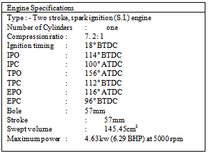
The engine used for the present experiments is an air cooled two stroke spark ignition engine. The major specifications of the engine are given in Appendix 1. The experimental set up is shown in plate No.1. The fuel metering system consists of a 5 litre tank for gasoline and 2T oil supply for carburettor. Fuel flow is measured with the help of calibrated burette and stop watch. A separate tank of 5 litre capacity is used for fuel injection system. In this mode the fuel consumption rate is measured with the help of a weighing machine and stop watch.The air flow rate is measured with the help of an inclined tube manometer and a drum fitted with orifice. The clutch of the engine is directly coupled with crankshaft and it is modified to take drive directly from crankshaft for dynamometer at high speeds instead of the conventional gear system which operates at a low speed.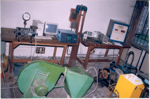 | Plate 1. Experimental set-up |
The test engine is coupled through the modified clutch with a Froude hydraulic dynamometer mounted on a cast iron test bed
6. Test Procedure
The basic quantities that were measured during the experimental investigations were, fuel consumption, air consumption, engine speed, torque output, exhaust gas temperature, spark plug temperature, injection timing, injection pressure, injection duration, throttle position, CO and HC emission concentrations and pressure crank angle diagrams of cylinder for evaluation of cylinder peak pressure data and cycle by cycle variation. Comprehensive experiments were carried out for both electronic injection systems and carburetion system over a wide range of operating parameters encompassing broad changes in engine speed, throttle position, injection timing, injection duration, start of injection and injection pressure.
7. Gasoline Direct Injection
The cylinder head of the engine was modified. The fins were cut on the other side of the spark plug fitted in the cylinder head. A hole was drilled and threading similar to the spark plug was done in the bush fitted in the hole. This was done to hold the injector in the adapter for supplying the fuel under the GDI mode directly into the cylinder. Experiments were conducted under the GDI mode and the start of injection and duration of injection were optimized for various speeds corresponding to different throttle positions by undertaking comprehensive experimental investigations. The engine was started directly in the GDI mode by selecting the start of injection and keeping the duration of injection as small as possible. Then the throttle was opened slowly and the load was applied as per requirements. The duration of injection was varied and optimized. The rough reference of duration of injection was taken from the bench test in the carburettor mode for that particular throttle and speed. The start of injection was optimized so that fuel gets sufficient time to atomize for combustion and simultaneously it was kept in mind to supply the fuel as close as possible towards the exhaust port closing point to minimize the scavenging losses. The optimum fuel injection pressure was found to be 6 bar. Injection pressure was kept constant by providing a fuel by pass line. The engine performance and emission characteristics were studied at different operating conditions. The detailed results are given in the next chapter.
8. Control of the Fuel Injection System
The fuel injection system was controlled by a manually controlled digital electronic control unit. Injection duration at different operating conditions was controlled manually by pre-selection of the crank angle for start and end of injection. Maximum power was adopted as criteria for optimization of the injection parameter.
9. Results and Discussion
9.1. Validation of Computed Results with Experimental Results
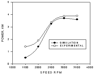 | Figure 1. Effect of speed on power carburettor mode throttle=80% |
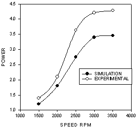 | Figure 2. Effect of speed on power GDI mode throttle=80% |
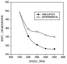 | Figure 3. Effect of speed BSFC carburettor mode throttle=80% |
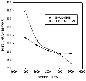 | Figure 4. Effect of speed on BSFC GIO mode throttle=80% |
 | Figure 5. Effect of speed on EGT carburettor mode throttle=80% |
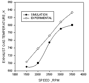 | Figure 6. Effect of speed on EGT GDI mode throttle=80% |
Figures 1 to 6 give the comparison of the results got from computer simulation and the measured results from experimentation. It is clear from the graphs that the results are comparable. The computed results satisfactorily follow the measured values.
9.2. Simulated Results
Parametric studies were carried out on the model to examine its potential for predicting the engine behaviour .The results obtained from these parametric studies are presented below. Figures 7 to 14 show the comparison of the computed engine performance obtained from gasoline in cylinder injection and carburetion modes.In view of better mixture preparation under the incylinder injection mode , the engine develops improved power as compared to the carburetted version under different throttle positions. This trend is reflected from the computed results shown in figures 7,9,11 and 13. As a consequence of the enhanced power output from the GDI engine , the specific fuel consumption improves, which is depicted in the graphs shown in Figs.8,10,12 and 14.It is clear from figures 9 and 10 that the power and BSFC vary with respect to start of combustion. Power is maximum when the start of combustion is 350 degrees ATDC and BSFC is minimum at the same timing. Hence this may be referred to as the MBT timing. This is due to better combustion characteristics at this timing. It is also clear that more power is developed in the GDI mode and also the BSFC is lower in the GDI mode.Figures 11 and 12 give the variation of power and BSFC with respect to duration of combustion. It is clear that maximum power and minimum BSFC are obtained when combustion duration is 50 degrees of crank angle. This is because pressure development with respect to crank angle is optimum at this duration and there is maximum work transfer from cylinder gases to piston. Also it is clear that power and BSFC are favourable in GDI mode as compared to carburettor mode. Further longer duration of combustion results in a slower rate of combustion leading to lower cylinder gas pressure, which reduces the engine power output. However shorter duration of combustion may lead to higher temperatures, which may increase the heat transfer, causing the power to fall.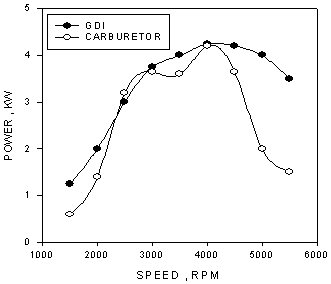 | Figure 7. Effect of speed on computed power throttle=80% |
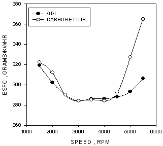 | Figure 8. Effect of speed on computed BSFD throttle=80% |
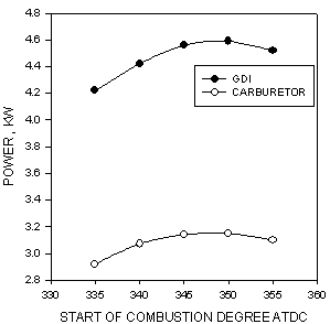 | Figure 9. Effect of start of combustion on power throttle=80% |
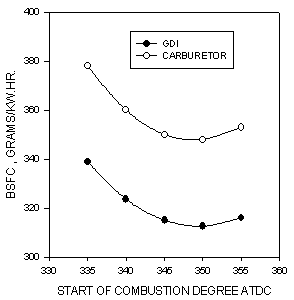 | Figure 10. Effect of start of combustion on power throttle=80% |
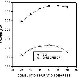 | Figure 11. Effect of combustion duration on power throttle=80% |
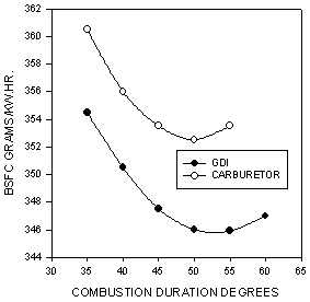 | Figure 12. Effect of combustion duration on BSFC throttle=80% |
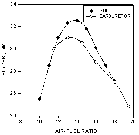 | Figure 13. Effect of air-fuel on power throttle=80% |
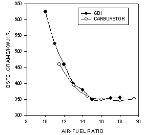 | Figure 14. Effect of air-fuel ratio on BSFC throttle=80% |
Figures 13 and 14 show the variation of power and BSFC with respect to air fuel ratio. It is seen that maximum power is produced with slightly rich mixtures when entire oxygen is consumed in cylinder and it is also clear that minimum BSFC is obtained with slightly lean mixtures when the entire fuel is consumed. It is also clear that GDI yields better performance as compared to carburettor mode.
10. Conclusions
(1). Gasoline direct injection can be effectively used to minimize fuel losses in a single cylinder two stroke cycle spark ignition engine.(2). The bsfc of the engine is reduced by 20% to 30%(3). There is upto 9% improvement in engine power.(4). CO emissions are reduced by 40%(5). There is upto 53% reduction in HC emissions.(6). Potential exists to revive the two stroke engine industry at the expense of some additional components.The existing two stroke engines in market can be redesigned with direct fuel injection system instead of existing carburettor system. This is going to replace the carburettor with a combination of injector , fuel pump , crank angle encoder and electronic control unit besides with various sensors.The future work lies in incorporating the compact microcontrollers in place of digital electronic control unit. Further multi hole injectors can be tried and tested in place of single hole injectors. More compact crank angle encoders can also be designed.
Appendix
References
| [1] | A. Franco et al , “Development of two stroke engines with direct injection”, SAE paper No.951776 |
| [2] | Huel-Huay Huang et al, “A review of technological approaches for reducing exhaust emission for two stroke cycle engines with in-cylinder injection systems”, SAE paper No. 951775 |
| [3] | Marco Nuti etal, “Twenty years of Piaggio direct injection research to mass produced solution for small 2T spark ignition engines”, SAE paper No. 980760 |
| [4] | William P.Johnson etal, “Electronic direct fuel injection for small two stroke engines”, JSAE paper No.9938067 |
| [5] | Koji Morikawa etal, “A study of exhaust emission control for direct fuel injection two stroke engine”, JSAE paper No.9938042 |
| [6] | Koji Morikawa etal, “A study of direct fuel injection two stroke engine for high specific power output and high engine speed”, JSAE paper No. 9938043 |
| [7] | Cornel Stan etal, “Development of a direct injection concept for two wheelers equipped with two stroke engines”, SAE paper No. 1999-01-1248 |
| [8] | M. Badami etal, “Comparison between direct and indirect fuel injection in an SI two stroke engine”, JSAE paper No. 9938066 |
| [9] | Omary Najibullah, Subramanyam J.P., Babu M.K. Gajendra and Bhatti T.S., “Design and development of a simple electronic fuel injection system for a single cylinder four stroke spark ignition engine”, pp.108-113, Proceedings of XIV National Conference on I.C. Engine and Combustion, Dec.8-10,1995, Pune,India. |
| [10] | BOOST user Guide version 4.0, AVL Austria. |
| [11] | E Antonelli etal, “A New GDI 2-Stroke Engine to Meet Future Emission Limits: The Design and Prototype Architecture.”SAE Paper No 2004-32-0041. |
| [12] | Dalibor Jajcevic, “CFD Study of Spray Design gor a GDI High performance 2-Stroke Engine”, SAE Paper No 2010-32-0014. |
| [13] | K D Sapate etal.,” Design And Development of Gasoline Direct Injection System For Small Two-Stroke Engine” Paper Volume 3, Issue 2, May-August (2012), pp. 346-353.IJMET |
 Abstract
 Reference
 Full-Text PDF
 Full-text HTML