-
Paper Information
- Next Paper
- Previous Paper
- Paper Submission
-
Journal Information
- About This Journal
- Editorial Board
- Current Issue
- Archive
- Author Guidelines
- Contact Us
Energy and Power
p-ISSN: 2163-159X e-ISSN: 2163-1603
2012; 2(4): 51-54
doi: 10.5923/j.ep.20120204.02
Electrical Energy Conservation in Automatic Power Factor Correction by Embedded System
 Abstract
 Reference
 Full-Text PDF
 Full-Text HTML
M. Ravindran , V. Kirubakaran
Rural Energy Centre,Gandhigram Rural Institute Gandhigram,Tamilnadu
Correspondence to: V. Kirubakaran , Rural Energy Centre,Gandhigram Rural Institute Gandhigram,Tamilnadu.
| Email: |  |
Copyright © 2012 Scientific & Academic Publishing. All Rights Reserved.
This paper presents a new method for power factor correction with low cost drives. Power factor control is a major role in the improvement of power system stability. Many of the existing systems are expensive and difficult to manufacturer. Nowadays many of the converters have no input power factor correction circuits. The effect of power factor correction circuit is used to eliminate the harmonics present in the system. This type of power factor correction circuit is mostly used in the Switched Reluctance Motor controller drive. Fixed capacitor systems are always leading power factor under at any load conditions. This is unhealthy for installations of power system. The proposed embedded system drive is used to reduce the cost of the equipment and increase the efficiency of the system. Experimental results of the proposed systems are included. It is better choice for effective cost process and energy savings.
Keywords: Power System, Power Factor Improvement, Capacitor, Embedded System
Article Outline
1. Introduction
- Most of the consumers consumed the electricity for the purpose of inductive load. The inductive load is act as a lagging power factor. The result of lagging power factor increases the power losses in the power system. The reactive power is compensated by real power by using suitable value of capacitors. This improvement of power factor is helps to avoid the heavy penalties and also offer incentives to the consumer. The existing work on power factor correction is having some disadvantages like switching operations and sensing stability of the system. In this proposed system is used to rectify the above problem. Power factor is the cosine angle between the voltage and current. This current and voltages are sensed by using instrument transformers like current transformer and voltage transformer. In this proposed method zero crossing detectors is used to converting the waveforms of voltage and current into TTL compatible square waves. The above square waves are fed into the microcontroller ATMEL 8951. The phase angle between the voltage and current is calculated by inbuilt computers in the microcontroller. The calculated values are comparing with actual load present in the system. The load on the system is maximum when the capacitor bank[1] is added in the system by using micro controller. These processes are continuously carried out and maintain the power factor in automatically. This paper proposes the following solutions to correct the power factor.Ø Reactive power is compensated by real power obtained from capacitors.Ø Automatic power factor correction so as to achieve electrical energy conservation.Ø Minimize the unwanted losses in energy and improve the efficiency of the power system.Ø Eliminating the electromechanical relays by means of solid devices.
2. Theory
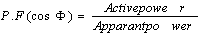
2.1. Power Factor
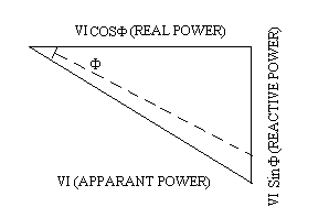
- Power factor indicates actual amount of power is delivered to the load.
 The direction of the current and voltage vectors are not same at all loads like inductive, resistive, and capacitive loads.
2.2. Resistive Load
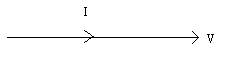
- For pure resistive load there is no phase difference between voltage and current. So the power factor is unity
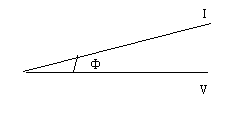
2.3. Inductive Load
- Current vector in the pure inductive load is lagging behind the voltage vector with angle 90o. ie) Cos 90= 0. No power[2] is consumed by inductive load. Practically pure inductance is not possible.It is having some small amount of resistance and reactance. So that angle of lagging is not exactly 90o.
2.4. Capacitive Load
 Current vector in the pure capacitive load is leading in front of the voltage vector with angle 90o.Pure capacitance is also not possible. It is also having resistance[3]. Hence angle of leading is not exactly 90o In RLC circuit the capacitor is used to reduce the angle between voltage and current.
 3. Performance of the Proposed System
- The following functions are to be considering for the proposed system.Ø Current signals are obtained from instrument transformer like potential and current transformers.Ø Zero crossing detectors are used to convert the waveforms of voltage and current into corresponding square waveform.Ø TTL is used to convert the square waveform to compatible waveform.Ø Converted waveforms are fed into a counter, positioned in the microcontroller.The counted pulses are converted into corresponding value of phase angle Ф
4. Experimental Setup
- Magnitude of the voltage and current are fed into themicrocontroller89C51.It is used to measure the phase shift between the voltage and current. ie) the cosine value of the electrical quantities like voltage and current are measured by using microcontroller. According to the power factor number of relays is energized or deenergised.The signal from microcontroller (either 0 or 1) is used to operate the relay. The relay contacts are closed when the capacitor is connected to the circuit through relay. Hence the power factor improves a vice versa happens when the signals are low.
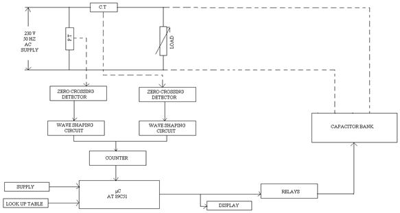 | Figure 1. Block diagram of Power factor correction |
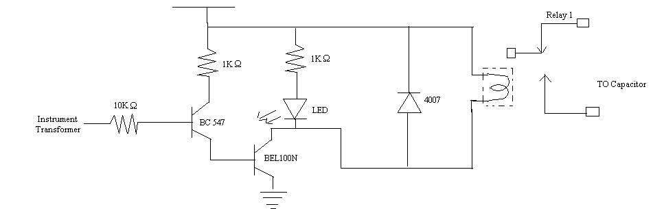 | Figure 2. Circuit diagram for power factor correction |
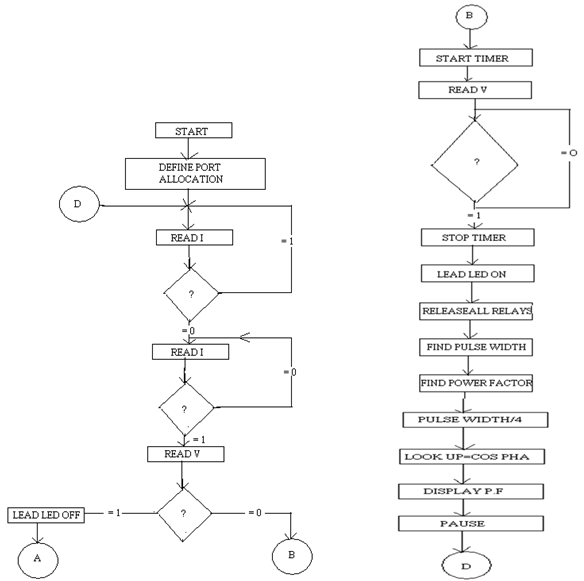 | Figure 3. Flow chart for Embedded system |
5. Embedded System
- Embedded system is a combination of hardware and software that forms the component of a larger system. It is a programmed system it consists of dedicated functions with minimal operations. This is also having number of divisions at different conditions. It is very useful for more applications. It is generally prepared for speed of operation, accuracy and reliability. Embedded application software performs the predefined function of the embedded device. This software can support such applications as the internet-mail and MP3 decodes.
6. Microcontroller 89C51
- This device is selected because it is an intel IX51 microcontroller. The intel IX51is a standard reference architecture and easy to adapt to a variety of design. The ATMEL 89C51 has a program memory unit on FLASH technology. FLASH ROM memory is a technology of starting programs in a controller and that can be erased without UV Eraser. So the erasing process is very fast. Hence it is called flash. The microcontroller actuates the necessary relay of the various power factors.
7. Zero Crossing Section
- Zero crossing section is having two zero crossing detector circuits. The alternating sine wave of voltage and current signals are fed into each zero crossing detector. This circuit is used to convert[5] the sine waveforms to corresponding square waveform. It helps to measure the power factor of the system.
8. Conclusions
- This paper has experimentally explained[6] the power factor correction by using embedded system. This proposed power factor correction circuit was simulated andexperimentally tested with Switched reluctance motor in different operating modes. Electric energy is consumed in our day to day life. It is utilized by different type of consumer like domestic and Industries. Unfortunately electric power cannot be stored in any form. So that the power may be meet the requirements of the consumers. Experimental results confirm the theory and prove the concept of the power factor correction. In this experimental setup is used to maintain the power factor by using static capacitors. These capacitors are switched on during peak load hours and switched off during lightly loaded hours. The power factor adjustment is used to maintain the stability of the power system.
References
| [1] | Rakosh Das Begamudre, “energy conversion systems”, New Age International Publishers, New Delhi, 2000. |
| [2] | S.Hasan saeed, D. K. Sharma, “Non-Conventional energy resources”, Katson publications, New Delhi, 2006-07. |
| [3] | G.D.Rai, “Non-Conventional energy sources”, Kannapublications, New Delhi, 2006. |
| [4] | Rybach, L., Megel, T., Eugster, W.J., “How Renewable are Geothermal Resources?” Geothermal Resources Council Transactions, Vol. 23, October 1999. |
| [5] | EPRI, “Renewable Energy Technology |
| [6] | G.Venkatesan, R. Arumugam, M.Vasudevan, S. Paramasivam and Vijayan 2006 “Modelling and Simulation of Novel Switched Reluctance Motor drive system with Power factor improvement, American journal of Applied Sciences 3(1):1649-1654 2006 ISSN 1546-9239, Science Publications. |
| [7] | Andrew K. Soubel, Energy Law Spring 2004, Chicago-Kent College of Law, soubel@msn.co |
| [8] | O’Neill, M.J., “Stretched Fresnel Lens SolarCon centrator for Space Power,” U.S. Patent6, 075,200, 2000. |