-
Paper Information
- Next Paper
- Paper Submission
-
Journal Information
- About This Journal
- Editorial Board
- Current Issue
- Archive
- Author Guidelines
- Contact Us
Energy and Power
p-ISSN: 2163-159X e-ISSN: 2163-1603
2012; 2(4): 46-50
doi: 10.5923/j.ep.20120204.01
An Experimental Comparison of two Solar Photovoltaic- Thermal (PVT) Energy Conversion Systems for Production of Heat and Power
 Abstract
 Reference
 Full-Text PDF
 Full-Text HTML
David A. G. Redpath 1, Harjit Singh 2, Christopher Tierney 1, Philip Dalzell 1
1Centre for Sustainable Technologies, University of Ulster at Jordanstown, Newtownabbey, Co. Antrim, N. Ireland BT37 OQB
2School of Engineering and Design, Brunel University, Uxbridge, Middlesex UB8 3PH,
Correspondence to: David A. G. Redpath , Centre for Sustainable Technologies, University of Ulster at Jordanstown, Newtownabbey, Co. Antrim, N. Ireland BT37 OQB.
| Email: |  |
Copyright © 2012 Scientific & Academic Publishing. All Rights Reserved.
Two solar photovoltaic-thermal (PVT) energy conversion systems are described and their performance tested under laboratory conditions. One of these was a simple Flat Plate (FP-PVT) design, with headers and risers for heat removal the other a fixed linear axis Compound Parabolic Concentrating solar PVT (CPC-PVT) energy conversion system with a heat-pipe for removal of solar gain. Both had a low iron glass cover for high transmissivity of solar radiation, and polycrystalline silicon solar photovoltaic cells adhered to the absorber. Heat loss coefficient for the FP-PVT collector was measured as 4.1W/m2/K and 3.5W/m2/K for the CPC-PVT solar collector. These solar collectors were tested under steady state conditions using the solar simulator facility at the University of Ulster’s Centre for Sustainable Technologies. The FP-PVT and the CPC-PVT had a combined efficiency of 66.8% and 53.4% respectively producing both heat and power.
Keywords: Solar PVT, CPCs, Heat-pipes
1. Introduction
- The Stern Report[1] has highlighted the rationale for the deployment of low carbon technologies to stabilise global greenhouse gas emissions at 550 ppm CO2eq[2]. Buildings account for around half of the UK’s total carbon emissions[3] and the usage patterns of these is directly related to energy consumption. In the first quarter of 2010 domestic and services sectors were responsible for 50% of total energy consumption within the UK[4]. In 2007, the UK government set a target to gradually improve the energy efficiency and carbon performance of buildings to achieve a zero carbon emission level for new homes by 2016[5]. Further, the UK government intends to set zero carbon targets for new non domestic buildings by 2019[6]. These standards are expected to assist the UK government significantly in reducing CO2 emissions from buildings and to achieve the 2050 target of an 80% reduction in carbon emissions compared to the 1990 baseline as set in the Climate Change Act 2008[7]. Typically solar energy conversion technologies are used to generate sustainable thermal or electric power. For example solar water heaters convert incident solar radiation into thermal energy, which is typically utilised, for domestic, commercial or industrialpurposes (photo thermal conversion); solar photovoltaics generate electricity (photovoltaic conversion) a hybrid of these technologies is known as a solar photovoltaic-thermal (PVT) collector. PVT solar systems combine photovoltaic (PV) and solar thermal components into one unit with a simultaneous provision of electric power and heat. It was reported by Zondag et al (2002) that hybrid PVT systems are more efficienct than conventional solar thermal or solar photovoltaic collectors per unit area[8]. Similarly to solar PV and solar thermal, PVT collectors can either have a planar or a concentrating geometry and theoretically any PV material such as crystalline, polycrystalline, amorphous-silicon or non-silicon thin-film cells could be incorporated within a PVT collector. The electrical conversion efficiency of PV cells decreases significantly with a rise in their temperature above standard operating conditions, therefore, cooling these is essential if the electrical conversion efficiency is to be maintained. The additional benefit is that low grade thermal energy is also generated from the same area. Open circuit voltage and the short circuit current are the most sensitive parameters to the rise in temperature especially in the case of silicon cells. To avoid long term damage to silicon cells their temperature should be kept below 60℃. Thus such systems as described in this paper would be ideal for preheating purposes and could be joined with other solar collector technologies such as evacuated tube solar water Heaters which are commercially available if higher outlet temperatures are required forming a solar cascade system. The rationale for the development of PVT systems is that in recent years the cost of silicon solar cells has fallen rapidly and improvements in efficiencies have also been realised, during the same time period the cost of solar thermal systems has remained relatively static and efficiencies have remained steady. If both technologies (photovoltaic and thermal) are combined then both cost and space saving’s would be the result. This paper describes the fabrication of two PVT systems; one of these was based on the simple flat plate solar water heater design (FP-PVT) the other was a novel design of solar PVT collector incorporating Compound Parabolic Concentrating (CPC) collector with a heat-pipe for removing solar gain from the absorber plate (CPC -PVT). The CPC -PVT solar collector developed in-house used heat-pipe technology to remove excess heat from the solar cells maintaining their efficiency as they warm up. A heat-pipe based system was chosen as previous research has reported that these are more effective in transient climates such as the UK[9]. Planar PVT systems have been studied extensively experimentally and numerically[10-14]. Different absorber geometries were investigated and a spiral flow design reported to have the highest combined thermal-PV efficiency of 62%[13]. A planar PVT system with rectangular channel absorber geometry achieved a combined efficiency of 65%[14]. The total output energy of a CPVT system depends on the solar energy input, ambient temperature, wind speed, the operating temperature of the PV cells and substrate and the heat extraction mode. Design decisions were made based on the concentrator type, coolant type & target thermal to electrical yield ratio and the solar fraction for optimizing the operation of these systems. Building integrated systems also have further requirements of light weight and compatibility with the architectural details of the building elements but this design consideration is outside the realm of this paper. Cooling of the PV cells can be achieved by circulating a suitable fluid, for example water, air, or a refrigerant (heat-pipe) and the heat carried away by the cooling fluid can be used for space and/or water heating. Up to a concentration ratio (CR) of 10 the cooling scheme for the solar cells can either be active or passive, but for the systems with CR>10 cooling has to be achieved using some active or forced circulation of the cooling fluid. Passive cooling of linear concentrators, CPC or V-trough, is complex and difficult to achieve due to a large area over which the PV cells are placed and so the active cooling is required. Design of absorber substrate to maximise the amount of heat transferred to the cooling medium (typically water or air) is a prime requirement[15]. Clearly, the best cooling scheme that will yield the highest conversion, electrical as well as thermal, efficiencies is yet to be identified. Low concentration PV systems, linear Fresnel non-imaging systems (lens or mirror based) and CPCs with planar reflectors, are more viable for building integration allowing more light to travel into the building interiors than the high concentration ones whilst using absorption materials opaque to visible light. If static these can be placed at any location on the buildings, but in that case a very limited concentration ratio, CR ≤2.5, is achievable. Within the options for concentrators devices, parabolic concentrators, Fresnel reflectors[16], compact linear Fresnel reflectors[17], V-trough reflectors[18] and CPCs[19-21] have been studied but still the best combination of solar concentrator type, cooling scheme and the PV cell type to yield maximum conversion efficiency for a range of geographical locations including the UK has yet to be experimentally determined.
2. Methodology
- To investigate the performance of solar PVT systems two solar photovoltaic thermal collectors were fabricated, assembled and installed alongside a commercial PV module. The first PVT system had reflective concentrators with a concentration ratio of 1.8, a heat-pipe from a proprietary evacuated tube solar collector for heat removal, and the whole system was incorporated within Styrofoam for lightness and to ensure excellent thermal performance by minimising heat losses (k=0.04Wm-1K-1). The second PVT system was constructed in a similar fashion to a flat plat collector[22] using copper sheet and tubes for the absorber plateFigure 2.1 shows a schematic diagram of the CPC -PVT, figure 2.2 a photograph of the FP-PVT under construction.
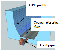 | Figure 2.1. CPC –PVT |
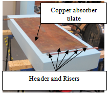 | Figure 2.2. FP-PVT under construction |
 | Figure 2.3. Side view of CPC-HP-PVT |
 | (2.1) |
 | (2.2) |
 | (2.3) |
 | (2.4) |
3. Results
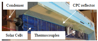
- Figure 3.1 is a photograph of the three collectors being tested under the solar simulator, table 3.1 is a summary of the experimental results
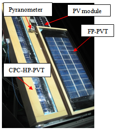 | Figure 3.1. Experimental set up |
|
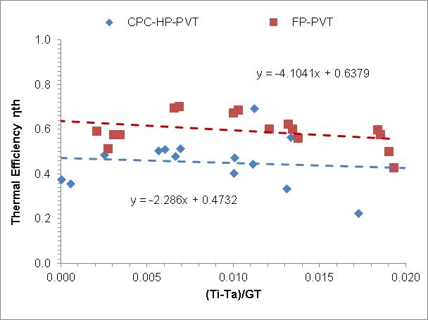 | Figure 3.2. CPC-HP-PVT and FP-PVT thermal efficiencies |
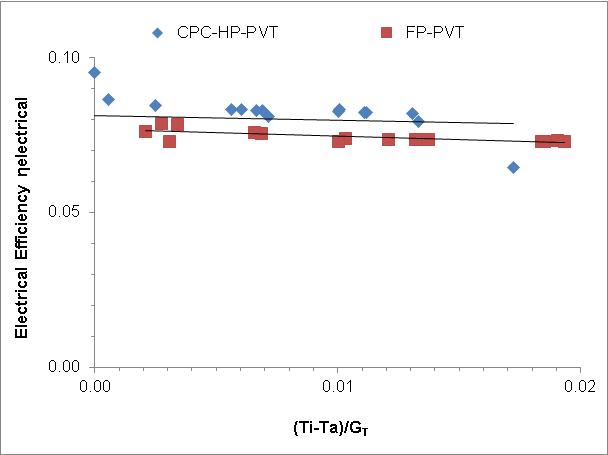 | Figure 3.3. CPC -PVT and FP-PVT electrical efficiencies |
 | Figure 3.4. CPC-PVT |
 | Figure 3.5. FP-PVT |
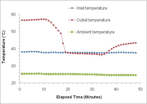
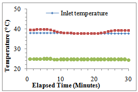
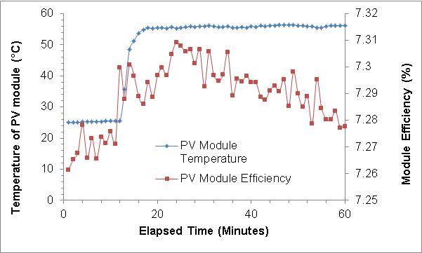 | Figure 3.6. Temperature and efficiency of control PV module |
4. Discussion
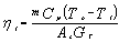
- As shown by the results presented in section 3 the CPC -PVT had a lower thermal efficiency than the FP- PVT with a heat removal factor of 0.488 compared to 0.638. The mean electrical conversion efficiency was 7.8% which was 0.4% higher than the value obtained for the FP-PVT and the highest value of 9.5%was 1.6% higher than the FP-PVT system. The advantages of using a heat-pipe absorber for transient climatic conditions was observed from the step change in radiation which simulates the overhead passing of a large cloud. It was experimentally demonstrated that the CPC -PVT system responded much more rapidly than the FP-PVT system which took a lot longer to cool down and heat up suggesting that in such conditions the CPC- PVT would be a more appropriate choice agreeing with the research published by[9].
ACKNOWLEDGEMENTS
- The authors would like to acknowledge the help from the technical support staff of the University of Ulster.