-
Paper Information
- Next Paper
- Previous Paper
- Paper Submission
-
Journal Information
- About This Journal
- Editorial Board
- Current Issue
- Archive
- Author Guidelines
- Contact Us
Energy and Power
p-ISSN: 2163-159X e-ISSN: 2163-1603
2012; 2(3): 33-38
doi: 10.5923/j.ep.20120203.02
A Single Phase to Three Phase Buck-Boost Converter cum Voltage Regulator suitable for Wind Power
Santosh Sonar , Tanmoy Maity
Department of Electrical Engineering, Indian School of Mines, Dhanbad, 826004, India
Correspondence to: Santosh Sonar , Department of Electrical Engineering, Indian School of Mines, Dhanbad, 826004, India.
| Email: |  |
Copyright © 2012 Scientific & Academic Publishing. All Rights Reserved.
In this paper the output of the single phase wind generator, common for low power application, is converted efficiently into a three phase power. A control system for impedance(z)-source inverter is designed for this wind power conversion. The variable single phase ac output of wind generator due to unpredictable variation in wind speed is suitably controlled through a closed loop system employing the buck-boost capability of z-source inverter. The z-source PWM inverter replacing the conventional PWM inverter provides the unique output voltage regulation by making an appropriate choice of boost factor under both variable generator voltage and variable load conditions. The closed loop controller carefully monitors the wind generator voltage and controls the shoot-through and non-shoot through duty cycles of the inverter to develop a three phase steady boosting voltage, which is not possible by conventional PWM control. The whole system is designed and verified through simulation and hardware arrangement. The system is simulated under arbitrary generator output condition both in surge and sag states and results steady three phase voltage across load. Similar steady output is also observed in case of variable load condition. The proposed closed loop system, therefore, can be used for smooth and effective dynamic and steady state control maintaining the level of three phase output at a desired level.
Keywords: Single Phase to Three Phase, Z-Source Inverter, Wind Generator, Closed Loop Control
Article Outline
1. Introduction
- Single phase wind generator seems attractive because of its simple construction and low cost. For rural energy supply the development of wind power especially as smaller machines in the 5 - 100 kW range is becoming popular. Wind power is used to provide electricity to individual homes or other facilities on a self-reliant basis. The power generated in the wind depends on air density, swept area of rotor and of course on upwind free wind speed. But actual power output depends on several other factors like type of machine or rotor, the sophistication of blade design and the various losses like friction loss, loss in pump and loss in the other equipment connected to it. Presently there are three main drive systems available[1]. They are:· Squirrel-cage induction generator· Doubly-fed (wound rotor) induction generator· Direct-drive synchronous generatorThe first one is the simplest and oldest system where the rotor speed variation is small and hence this is normally referred to a constant speed turbine. The main operating characteristic of the squirrel cage induction generator is that this always consumes reactive power. Also, this type ofgenerator tends to slow down voltage restoration after a fault and this can lead to voltage and rotor-speed instability. When the voltage does not return quickly enough, the generator continues to accelerate and consumes even larger amount of reactive power. To prevent these types of instabilities, active voltage regulators like the Static VAR compensator (SVC or STATCOM) are included in the system as detailed in[2]. The self-excited induction generator (SEIG) has been proved to be a better replacement due to several advantages such as ruggedness, brushless, maintenance-free features, off-the shelf availability, reduced unit cost, no required synchronization system and no need for DC excitation[3]. However, they must deliver power to the consumer with acceptable form and so, this requires suitable controllers. The critical function of those controllers would be to provide a required variable capacitive reactive power (VAR) to maintain a constant voltage across the variable load at varying prime mover speed[4]-[6]. In[7], the voltage and frequency control are investigated by varying the effective rotor resistance of a self-excited slip-ring induction generator. A study is done for SEIG employing a STATCOM through a sine PWM inverter working in synchronous mode[8].The other two generating systems are variable-speed systems. In the doubly-fed induction generator (DFIG), a back-to-back voltage source converter feeds the three-phase rotor winding that results the mechanical and electrical rotor frequency decoupling and the electrical stator and rotor frequency matching, independently of the rotor speed[9]. A dynamic model with reduced-order double cage representation for the DFIG and its associated control and protection circuits has been developed and stability study is presented in[10]. A grid-connected wind driven doubly fed induction machine with stator-flux-oriented vector control approach is also presented in[11] for optimum active power control. In the direct-drive synchronous generator, the generator is completely decoupled from the grid by two converters- one is connected to the stator winding and another is connected to the grid. For the variable speed operation, this acts as a frequency converter that can limit the current to rated values during dips, and continue to deliver real power and reactive power at reduced voltage levels. Therefore, in the event of a fault, these turbines could stay connected to the grid and may help the conventional power stations rebuild the voltage after grid failures[12]. A mechanical interface consists of step up gear and a suitable coupling transmitter, which is connected between wind turbine and Synchronous Generator (most of the cases, permanent magnet Synchronous Generator (PMSG) are used). Since the wind is an intermittent source of energy, the output voltage and frequency from generator vary according to wind velocities. This inconsistency in output is the major drawback of wind power system. Traditionally, this variable AC power from this generator is rectified first into DC and then is regulated for constant voltage by using dc to dc converter. The constant DC output then is fed to the load at the required level of voltage and frequency employing a PWM inverter. The major requirement in this wind energy system is to realize and maintain consistently a constant voltage at the load terminal using minimum amount of circuitry. One recent application for permanent magnet generator with ac series regulator is proposed in[13], but the control circuit is complex in nature. In[14] a new topology of general voltage regulator is described based on the ac-ac buck-boost converter. The controller used, provides good dynamic response for large input voltage variations, but not suitably tuned for wind power application.The focus in this paper is to employ impedance source inverter in place of conventional system and converting the single phase supply to a three phase regulated supply through a simple closed loop control. The buck-boost capabilities of impedance source inverter are expected to take care both the generator output voltage and load variations. A number of switching methods have been proposed so far to control Z-source inverter shoot-through and non-shoot through states[15]. The methods include the sinusoidal PWM (simple boost control[16], maximum boost control[17] and modified space vector modulation based PWM[18]). Different applications of Z –Source inverter are also proposed, which includes motor drives[16], fuel cell[19] and renewable energy sources like solar system[20]. In line with the recent advancements of z-source inverter applications in different alternative source of power, this work deals with a proposed solution where z-source inverter is used with wind generator to provide a stable uninterrupted constant voltage power source employing simple control system.
2. Operation of Impedance Source Inverter
- An Impedance (z) source inverters has been already proposed and proven as an alternative power conversion system because of its steady state voltage buck and boost characteristics using a unique impedance network. Z-source inverter has a wide range of obtainable voltage. It contains two-port network that consists of a split-inductor and capacitors which are connected in ‘X’ shape to provide an impedance source or z-source. It is coupled between the converter and the dc source. The “Figure. 1” represents the circuit model of the z-source inverter where two switches S1 & S2 are arranged to show the shoot through switching and non shoot through switching. The switching can be performed in three states, the first state when S1 is turned on and S2 is turned off, which is the shoot through state. During this state, the input diode is reversely biased, the capacitors charge the inductors, and the output current is freewheeling through the diode. The duty ratio of this state is d. The second state is when both switches are turned off, which is the traditional zero state. During this state, the capacitors are charged by the inductors, and output current is freewheeling through the diode. The third state is when S1 is turned off and S2 is turned on, which is the active state having duty ratio m (m+d ≤ 1) and the inverter applies voltage to the load.From the symmetry and the equivalent circuits, the output peak phase voltage from the z-source inverter can be expressed
 as whereas the output peak ac phase voltage of the traditional PWM inverter is given by
  Here V0 is the dc source voltage, M is the modulation index. B ≥1 is the boost factor taken from the shoot-through zero state, which is further expressed as
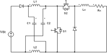 | Figure 1. The circuit model of the z-source inverter |
3. The Closed Loop System Analysis
- Similar to the traditional wind energy conversion system the basic components required to complete the proposed closed loop system arei) Wind turbine – converts the kinetic energy of wind into rotary mechanical energyii) Gear Box –it provides a mechanical interface and a suitable coupling transmitteriii) Generator – single phase permanent magnet synchronous generator iv) Z–network – used to employ a LC network to couple with inverter main circuitv) Inverter- it consist of a sine wave PWM voltage source inverter with switching circuit controlled by feed-forward closed loop system.
 | Figure 2. Block diagram of the closed loop control system |
 where R and r are assumed as the internal resistances of capacitor C and inductor L respectively.Now the transfer function of the z-network having two inductances and two capacitances can be obtained through mesh analysis as
 where R and r are assumed as the internal resistances of capacitor C and inductor L respectively.Again, considering a symmetrical network (L1 = L2 = L and C1 = C2 = C ), the transfer function reduces to,
 | (1) |
 | (2) |
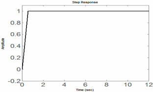 | Figure 3. Step response of the simulated system |
4. Simulation and Experimental Results
- To verify the above principle, simulations are carried out for the proposed closed loop system in SIMULINK environment. Since the wind turbine runs with variable speed and gives variable single phase output voltage at the generator end, an arbitrarily variable ac sinusoidal voltage source is used in place of turbine-generator set for the work. An LC filter with suitable cut-off frequency is placed in-between the three phase load and inverter bridge to filter out the harmonics. For the simulation the parameters of the z-source network are selected as C= 1100 μF and L=1.5 mH.Sine wave PWM method is chosen with modulation index M = 0.7 and switching frequency =10 kHz. Three-phase variable resistive load is chosen for this simulation. Proportional controller gain obtained by hit and trial method is kp=1. Now, to observe the dynamic performance of the system, sudden generator voltage sag and voltage surge are applied separately. First the generator single phase ac voltage steady at 220 volt is dropped to 185 volt for a short duration shown in “Figure. 4(a)”. Similarly, the input voltage is suddenly increased from 220 volt to 260 volt shown in “Figure. 5(a)”. The corresponding output three phase voltages measured across line to line three phase load shown in “Figure. 4(b)” and “Figure. 5(b)” respectively shows no variation at all. In both the cases the response of z-network capacitor voltages and z-network inductor currents are recorded and presented in “Figure. 4(c)”, “Figure.4(d)” and “Figure. 5(c)”, “Figure. 5(d)” respectively.
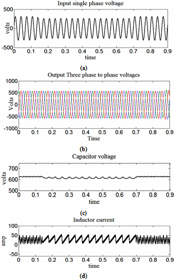 | Figure 4. Simulation results under sag condition (a) generator voltage (b) three phase output voltage (c) voltage across z-network capacitor (d) current at z-network inductor |
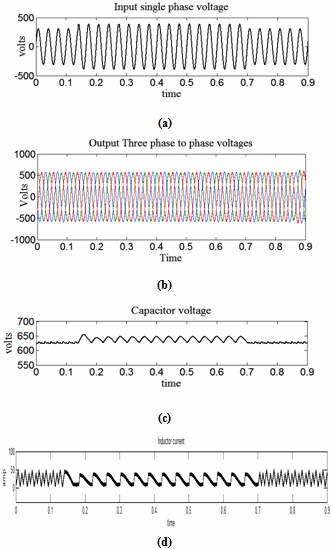 | Figure 5. Simulation results under surge condition (a) generator voltage (b) three phase output voltage (c) voltage across z-network capacitor (d) current at z-network inductor |
| ||||||||||||||||||||||||||
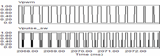 | Figure 6. Sample switching PWM pulse without shoot-through (B=1) and pulse with shoot-through (B>1) |
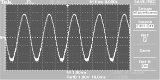 | Figure 7. One of the load phase voltage waveforms in hardware circuit |
5. Conclusions
- Three phase inverter based on impedance (z)-source network with its boosting capability suitably controls and regulates the wind generator variable voltage and load variations. The closed loop system developed is used not only for smooth and effective dynamic and steady state control but also boost the level of three phase output at a desired level. In this paper, the system is modelled, appropriate transfer functions are derived and stability is achieved with a suitable design of controller. The whole system is simulated and set of results and waveforms obtained, supports the regulation behavior. The comparative results show that the obtained shoot-through zero states of the z-source inverter can efficiently boost the low level single phase input into a steady three phase higher level ac, which is not possible with the help of conventional inverter.
ACKNOWLEDGEMENTS
- This work is carried out with the financial support of University Grants Commission (UGC) under a major research project running at ISM, Dhanbad, India.
References
| [1] | J. G. Slootweg, & W. L. Kling, “Is the Answer Blowing in the Wind”, IEEE power and Energy magazine, vol.1, no.6, pp.26-33,2003. |
| [2] | P. F. Toledo, H. Xie, & K. T. Hogskolan, Wind Farm in Weak Grids Compensated with Statcom, http://www.elkraft.ntnu. no/smola2005/Topics/8.pdf. |
| [3] | B. Singh, S. S. Murthy, & S. Gupta, “ Analysis and design of STATCOM-based voltage regulator for self-excited induction generators”, IEEE Trans. Energy Conversion, vol.19, no.4, pp.783-790,2004. |
| [4] | T.F. Chan, “Capacitive requirements of self-excited induction generators”, IEEE Trans. Energy Convers, vol.8, no.2, pp.304-311,1993. |
| [5] | B. Singh, & L.B. Shilpakar, “Analysis of a novel solid state voltage regulator for a self-excited induction generator”, IEE Proc. Gen. Transm. Distrib, vol.145, no.6, pp.647-655,1998. |
| [6] | A. A. Shaltout, & M. A. Abdel- Halim, “Solid-State control of wind driven self excited induction generator”, Electric Mach. Power Syst., vol.23, no.5, pp.571-582,1995. |
| [7] | T. F. Chan, K. A. Nigim, & L. L. Lai, “Voltage and frequency control of self excited slip-ring induction generators”, IEEE Trans. Energy Convers, vol.19, no.1, pp.81-87,2004. |
| [8] | T. Maity, & S. N. Bhadra, “A Study on STATCOM Excited Variable Speed Squirrel Cage Induction Generator”, in Proceedings of Int. Conf. Energy, Information Technology and Power Sector, PEITSICON2005 –IEE, Kolkata, 254 -257, 2005. |
| [9] | S. Muller, M. Deicke, & R.W. De Doncker, “Doubly-fed induction generator system for wind turbines”, IEEE Industry Application Magazine,vol.8,no.3,pp. 26 – 33,2002. |
| [10] | J. B. Ekanayake, L. Holdsworth, X. G. Wu, & N. Jenkins, “Modeling and Control of a Wind Turbine Driven Doubly Fed Induction Generator”, IEEE Transactions on Power Systems, vol.18,no.2, 803 –809, 2003. |
| [11] | A. Tapia, G. Tapia, J. X. Ostolaza, & J. R. Saenz, “Modeling and control of a wind turbine driven doubly fed induction generator”, IEEE Transactions on Energy Conversion, vol.18,no.2,pp. 194–204,2003. |
| [12] | J. Matas, M. Castilla, J. M. Guerrero, Vicuña L García de, & J. Miret,“Feedback linearization of direct-drive synchronous wind-turbines via a sliding mode approach”,IEEE Trans.On Power Electronics, vol.23,no.3,pp.1093-1103,2008. |
| [13] | A. Pennatini, P. E. Bagnoli, & E. Franchi, “AC series voltage regulator for permanent magnet generators”, IEEE proc. Int. symp. Power Electronics Electrical Drives Automation and Motion, 2010, pp. 484-489. |
| [14] | N. Vazquez, A. Velazquez, & C. Hernandez, “AC Voltage Regulator Based on the AC-AC Buck-Boost Converter”, IEEE proc. Int. symp. Industrial Electronics, 2007, pp 533-537. |
| [15] | F. Z. Peng, “Z-Source inverter”, IEEE Trans. Ind. Application,vol. 39,no.2,pp. 504–510,2003. |
| [16] | F. Z. Peng, A. Joseph, J. Wang, M. S. Shen, L. Chen, & Z. G. Pan, “Z-Source Inverter for motor drives”, IEEE Transaction on power electronics, vol.20,no.4,pp. 857-863,2005. |
| [17] | F. Z. Peng, M. Shen, & Z. Qian, “Maximum boost control of the Z-source inverter”, IEEE Transactions on power electronics,vol. 20,no.4,pp. 833-838,2005. |
| [18] | S. Thangaprakash, & A. Krishnan, “Z-source Inverter Fed Induction Motor Drives–a Space Vector Pulse Width Modulation Based Approach”, Journal of Applied Sciences Research, vol.5,no.5, pp.579-584,2009. |
| [19] | F. Z. Peng, M. Shen, & K. Holland, “Application of Z-source Inverter for Traction Drive of Fuel Cell”, IEEE Transactions Power Electronics,vol. 22,no.3, pp. 1054–1061,2007. |
| [20] | Y. Huang, M. Shen, F. Z. Peng, & J. Wang, “A Z-Source Inverter for Residential Photovoltaic Systems”, IEEE Transaction on Power Electronics, vol.21,no.6, pp.1776-1782, 2006. |
 Abstract
 Reference
 Full-Text PDF
 Full-Text HTML