P. Danaiah , P. Ravi Kumar
National Institute of Technology, Warangal Andhra Pradesh, India
Correspondence to: P. Danaiah , National Institute of Technology, Warangal Andhra Pradesh, India.
| Email: |  |
Copyright © 2012 Scientific & Academic Publishing. All Rights Reserved.
Abstract
The effect of ignition energy on lean operation of lean burn engines is currently being investigated. All previous engine investigations have presented results on relatively quiescent combustion induced turbulence and entrainment of the mixture into the plasma jet substantially. This improves the lean operating capability. The objective of the present investigations is to investigate the performance, combustion characteristics and emission levels of high energy, breaker- less, transistorized coil ignition system with surface discharge extended electrodes. A comparison is also made with that of a lower energy conventional system with normal spark plug and extended electrode plug.
Keywords:
Lean Operation, Spark Plug, Extended Electrode Plug
Cite this paper:
P. Danaiah , P. Ravi Kumar , "Evaluation of Performance and Emission Characteristics of Lean Combustion with High Energy Spark Ignition", Energy and Power, Vol. 1 No. 1, 2011, pp. 21-25. doi: 10.5923/j.ep.20110101.04.
1. Introduction
Recent investigations which are mostly confined to conventional low turbulence combustion systems, have been carried out to study the effect of ignition system parameters such as discharge current level, duration[1,2] and plug type[3,4,5,6,7]. It has been found that an increase in discharge current beyond a level of 50 to 100milli amperes is somewhat less effective than increased duration. A surface discharge plug has been shown to produce the improved ability to ignite a lean mixture reliably under adverse condition of pressure, temperature, turbulence etc, over the normal type of plug. Multiple electrode plug improves the initial burning rate and reduces cyclic variability[8]. Use of a plug with platinum tipped electrodes extends the lean ignition limit by allowing a wider gap and a reduced electrode diameter, which resulted in less heat loss from the initial spark kernel [9].Brake down mode ignition, which releases the ignition energy within a few nanoseconds has been shown to reduce initial burning time, improve combustion stability ad obtain leaner operating capability[7].
1.1. System Description
The ignition system used in the present work is developed by M/s. Robert Bosch of West Germany, for methanol operated high compression C.I Engines. Which is shown in fig. 1.0 it mainly consists of a distributor with inductive pick up,a transistorized control unit, an ignition coil (24 volts) and a ballast resister? The spark plug has three outer electrodes which are parallel to the central electrode to have surface gap. This ignition system was used to study the effect of an improved Ignition system on lean combustion. The plug is located centrally in the combustion chamber, with an inclination of 65⁰ to the horizontal. The plug tip is extended deep into the combustion chamber, by 10mm. This produces a spark nearly at the center of the combustion chamber, reducing flame travel distance. The plug is water-cooled to prevent the plug tip becoming red hot and initiating pre-ignition. 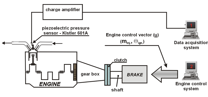 | Figure 1. Schematic diagram of the experimental stand for pressure measurements. |
2. Specifications of the Engine
3. Experimental Approach
The dynamometer, coupled to the test engine is first set at constant speed mode. Then the engine is started and kept under operation for an initial warm-up period of 20 minutes. Then the throttle is fixed at constant position for all the air fuel ratios tried. Manifold vaccum is maintained at 60mm of Hg i,e 60*133,322Pa to obtain constant air flow rates. For each setting the fuel flow rate alone is varied and the ignition timing is manually adjusted to obtain MBT condition that is the point at which the dynamometer indicates the maximum load.Three tests are conducted as indicated below;(i) Lower energy ignition system with conventional normal type plugs (LEIGCP).(ii) Lower energy ignition system with extended electrode plugs (LEIGEEP).(iii) Higher energy ignition system with extended electrode plug (HEIGEEP)The results obtained in the present investigation are discussed below.
3.1. Performance
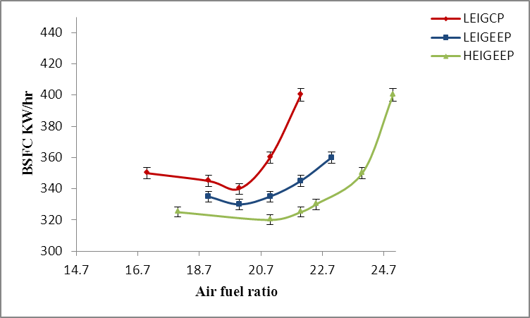
Figures 1.1, 1.2, and 1.3 represent the variation of brake power, BSFC, and brake thermal efficiency with air fuel ratio respectively. It can be see that by using higher energy ignition system with extended electrode plug (HEIGEEP) it is possible to operate the test engine with a wider range air fuel ratios, I.e., from 18:1 to 24.5:1 of air fuel ratios. For both the ignition systems the power drops down at leaner operations. However, the dropping trend for LEIGCP is much steeper compared to HEIGEEP. At an air fuel ratio of 21:1the power for HEIGEEP greater by 0.38 kW. This amounts to an 11.2% increase over the base engine (LEIGCP). This is believed to be due to a faster combustion, made possible by the HEIGEEP.The brake thermal efficiency is at its peak for HEIGEEP at an air fuel ratio of 21:1 while it is at 20:1 for the LEIGCP. The brake thermal efficiency drops down more rapidly for LEIGCP than for HEIGEEP. In the leaner range, the percentage increase in brake thermal efficiency for HEIGEEP and LIEGEEP compared, to LEIGCP are 7.6% and 5.9% respectively. BSFC improvements of 10% and 3.9% are obtained for HEIGEEP and LEIGEEP compared to LEIGCP, at an air fuel ratio of 21:1.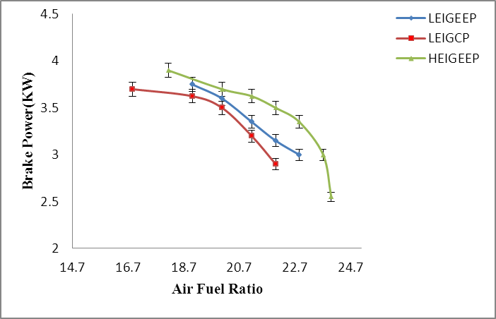 | Figure 1.1. variation of brake power with air fuel ratio. |
 | Figure 1.2. Variation of BSFC with air fuel ratio. |
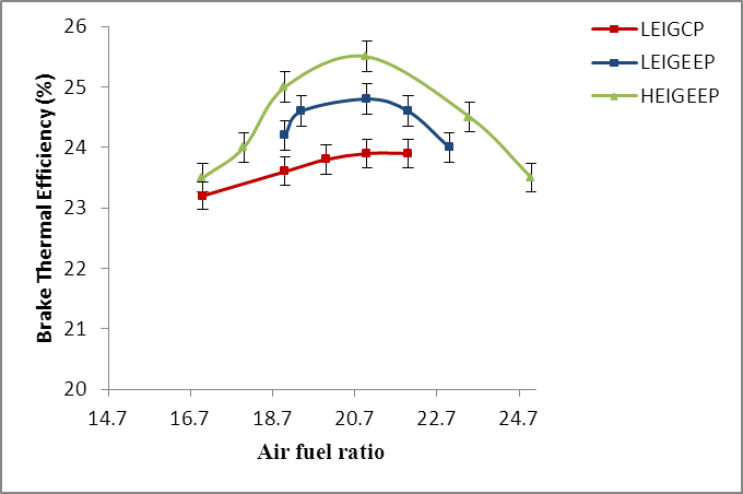 | Figure 1.3. Variation of brake thermal efficiency with air fuel ratio. |
3.2. Combustion
Figures 1.4, 1.5, and1.6 indicates the variation of combustion duration ignition delay and MBT timing with the air-fuel ratio respectively. Generally, for any type of ignition system, the combustion duration increases at leaner air fuel ratios indicating slower combustion. Due to faster combustion the combustion duration is lower for HEIGEEP compared to LEIGEEP and LEIGCP systems. However for the operation beyond 20:1 of air fuel ratio on leaner side the combustion duration appears to be decreased for LEIGEEP and LEIGCP. This is due to the fact that the combustion is partial and rapid deterioration of combustion quality in this range.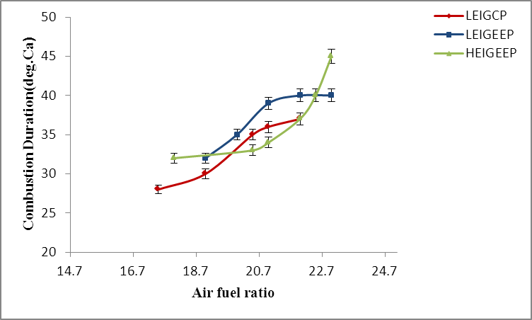 | Figure 1.4. Variation of combustion duration with air fuel ratio |
At a air-fuel ratio of 21:1the reduction in combustion duration for HEIGEEP system is 5degrees of crank angle and it is 3 degrees of crank angle at 20:1 air fuel ratio for LEIGEEP compared to the base LEIGCP system. These reductions in combustion time are due to the shorter flame travel distance of the extended electrode plug as it is located at the center of the combustion chamber. Further the combustion is more stable for HEIGEEP even on leaner range because of higher ignition energy for stable ignition compared to the base system.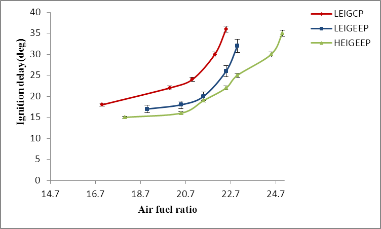 | Figure 1.5. Variation of ignitation delay with air fuel ratio. |
The ignition delay measured is composed of physical and chemical delays. Fig.6.7 shows that the delay period increases progressively at leaner mixtures for all types of ignition systems. But the increasing trend is more rapid for LEIGCP and LEIGEEP than for HEIGEEP system. It is evident that the ignition delay is lowest for HEIGEEP at leaner air fuel ratios. Lean misfire limit depends on the ignition energy rather that the type of plug ad its location in the cylinder head. At an air fuel ratio of 21:1the reduction in ignition delay for HEIGEEP and LEIGEEP are 10.9 and 8.0 in degrees of crank angle respectively compared to the base LEIGCP system. These reductions in ignition delay are believed to be the result of increased pre-flame reactions due to higher energy exchange between spark and the charge.
3.3. MBT Timing
Due to longer ignition delay and slower pre-flame reactions, the MBT timing is progressively greater with leaner air fuel mixtures operations. Hence for all ignition systems the MBT timing is greater for lean mixture ratios as shown in the fig 1.6. One would normally expect a HEIGEEP system to exhibit a smaller MBT spark advance as a result of faster combustion. However HEIGEEP has a MBT spark angle of about 10degrees large at air fuel ratio of 21:1 the slower burning LEIGEEP SYSTEM. This is a result of LEIGCP with increasing spark advance. The lower ignition energy may not be sufficient to ignition the mixture as cylinder pressure and temperature are lower in that condition. Among lower energy ignition systems with conventional normal plug and extended electrode, the extended electrode has a better ignitability to make the burning faster as the plug tip is located approximately at the centre of the combustion chamber.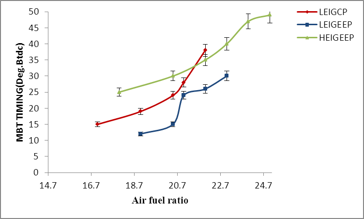 | Figure 1.6. Variation of MBT timing with air fuel ratio. |
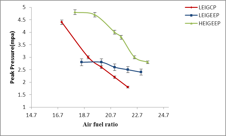 | Figure 1.7. Variation of peak pressure with air fuel ratio. |
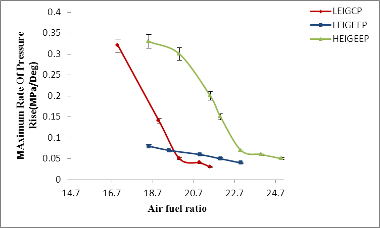 | Figure 1.8. Variation of maximum rate of pressure rise with air fuel ratio. |
3.4. Peak Pressure and Maximum Rate of Pressure Rise
It is seen from the figs.1.7 and 1.8 that the peak pressure ad maximum rate of pressure rise are the highest for HEIGEEP among the three ignition system at all the air fuel ratios. This is due to the faster burning of air fuel mixture using HEIGEEP compared to the base LEIGCP system. Peak pressure and maximum rate of pressure rise are found to be decreasing with the increase in air fuel ratios. This is due to the larger energy content in the charge at lower air fuel ratios and also due to the lower flame velocity in the leaner region.
3.5. Exhaust Gas Temperature
The exhaust gas temperature variation verses the air-fuel ratio is shown in fig.1.9. The exhaust gas temperature decreases with the increase of air fuel ratio. This is because of the combined effect of lower energy input in the charge and combustion inefficiencies at leaner air fuel ratios.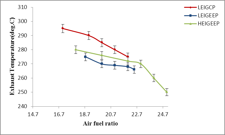 | Figure 1.9. Variation of exhaust temperature with air fuel ratio. |
The LML air fuel ratio for HEIGEEP is the highest with a value of 24.5:1 compared to LEIGCP systems for which it is 22.3:1ad 21.6:1 respectively. For HEIGEEP, the lean limit is extended by an air fuel ratio of 2.9 when it is compared with LEIGCP. This is due to higher ignition energy which makes it possible to obtain stable ignition even on leaner homogeneous mixtures for HEIGEEP and LEIGEEP systems is lower by 58%(240rpm) ad 35% (100rpm) compared to LEIGCP.
3.6. Performance
(i) The HEIGEEP system gives a higher power output of 0.38 KW, which amounts to an 11.5% increase, when compared to the base LEIGCP system.(ii) The peak break thermal efficiency is attained with the HEIGEEP system. The percentage increase in break thermal efficiency for HEIGEEP and LEIGEEP are 8.6% and 5.9% respectively. Similarly BSFC improvements are 10% and 3.9% for HEIGEEP and LEIGEEP respectively compared to the base ignition system.
3.7. Combustion
(i) Combustion duration for HEIGEEP and LEIGEEP systems are much less compared to the base system. The reduction in combustion time I crank angles for HEIGEEP and LEIGEEP systems are 5 degrees and 3 degrees respectively.(ii) Compared to LEIGECP, ignition delay is reduced by 10.9 and 8 degrees of crank angle for HEIGEEP and LEIGEEP systems respectively.(iii) MBT timing is degrees greater for HEIGEEP and 9 degrees less for LEGIEEP compared to base LEIGCP systems. The peak pressure ad maximum rate of pressure rise is more for HEIGEEP a system.(iv) The lean limit of HEIGEEP and LEIGEEP are extended by air fuel ratio 2.9 and 0.7respectively.
3.8. Emissions
Generally CO emission is much less for HEIGEEP system compared to base system. However there is no change in CO emission among all the systems at an air fuel ratio of 21:1.fig 1.10 indicates variation of CO with air fuel ratioThere are 58% and 35% reductions in HC emissions for HEIGEEP and LEIGEEP systems compared to the base system.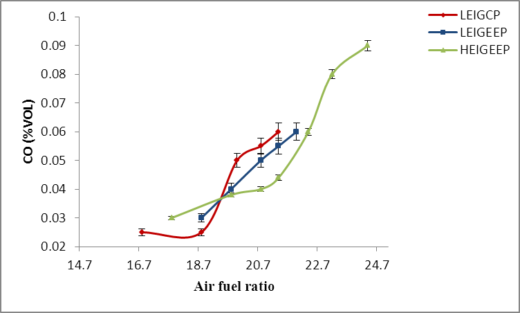 | Figure 1.10. variation of CO with air fuel ratio. |
4. Conclusions
1) The brake thermal efficiency drops down more rapidly for LEIGCP than for HEIGEEP.2) BSFC improvements of 10%and 3.9% are obtained for HEIGEEP and LEIGEEP compared to LEIGCP3) the peak pressure ad maximum rate of pressure rise are the highest for HEIGEEP among the three ignition system at all the air fuel ratios4) The exhaust gas temperature decreases with the increase of air fuel ratio.5) The HEIGEEP system gives a higher power output of 0.38 kw, which amounts to an 11.5% increase, when compared to the base LEIGCP system
Nomenclatures
BSFC: Brake specific fuel consumptionLML: Lean misfire limit
References
| [1] | L.R.Stei, R.A. Gentry and C.W. Hirt, Computer Methods in Applied Mechanics and Engineering. vol.II, pp.57, 1977 |
| [2] | J.N.Tunstall, on the Derivation of Conservative Finite-Differece Expressios for the Navier-storkes Equatios, union Carbide Corpn., Nuclear Division Report K/csd-5, oak Ridge, Team, April 1977 |
| [3] | Herbsleb, K.S., Lorzensen., L. and Koefoed, E., “ Lean combustion in a high compression for stroke gasoline engine”, SAE paper 810786, 1981 |
| [4] | Matthes, W.r., and Mc. Gill R.H. “ Effect of the degree of fuel atomization of single-cylinder engine performance”, SAE paper 760117, 1976 |
| [5] | Cloutman, L. D., Dukowicz, J. K., Ramshaw, J. D., Amsden, A. A.: CONCHAS-SPRAY: A computer code for reactive flows with fuel sprays, Los Alamos National Laboratory Report LA-9294-MS, 1982 |
| [6] | Anthony A. et al “ The KIVA-II Computer Program for Trasiet Miltidimesional Chemically Reactive flows with sprays” Los Alamos National Laboratory Report LA-.paper No.872072-1981 |
| [7] | Amsden A. A, Ramshaw J.D and Rourke P.J.O and Dukowocz J.K , KIVA: A computer program for two and Three Dimensional Fluid flows with chemical reactions and fuel sprays. Los Alamos National Laboratory Report, LA-10245-MS, 1985 |
| [8] | T. Kondoh, A. Fukumoto, K. Ohsawa and Y.ohkubo, An Assessment of of a multi-dimensional Numeriacal Method to predict the flow in internal combustion engines, SAE 850500, 1985 |
| [9] | Ricardo, H.R., “Report of the Empire Motor Fuel committee”, Proc. Inst. Auto. Engr., 18, Part 1 1923-24 |
 Abstract
 Reference
 Full-Text PDF
 Full-Text HTML