-
Paper Information
- Paper Submission
-
Journal Information
- About This Journal
- Editorial Board
- Current Issue
- Archive
- Author Guidelines
- Contact Us
Electrical and Electronic Engineering
p-ISSN: 2162-9455 e-ISSN: 2162-8459
2023; 13(1): 6-11
doi:10.5923/j.eee.20231301.02
Received: Dec. 11, 2022; Accepted: Jan. 11, 2023; Published: Jan. 31, 2023

Optimal Placement of UPFC in Distribution Network for Voltage Stability Improvement
 Abstract
 Reference
 Full-Text PDF
 Full-text HTML
Joshua Dantuo1, Isaac Kofi Otchere1, Bernard Arhin1, Kok Boon Chin2
1Department of Computer and Electrical Engineering, University of Energy and Natural Resources, Sunyani, Ghana
2Department of Electrical Engineering, Universiti Tun Hussein Onn Malaysia
Correspondence to: Isaac Kofi Otchere, Department of Computer and Electrical Engineering, University of Energy and Natural Resources, Sunyani, Ghana.
| Email: |  |
Copyright © 2023 The Author(s). Published by Scientific & Academic Publishing.
This work is licensed under the Creative Commons Attribution International License (CC BY).
http://creativecommons.org/licenses/by/4.0/

The recent increase in load demand has subjected the existing power network to voltage stability issues, which can subsequently result into overall system blackout when strategic measures are not adopted to maintain the power system stability. The purpose of this study is to analyse and resolve voltage stability related issues in the power system using UPFC. The study was conducted by modelling IEEE 14 bus test systems in MATLAB/Simulink environment and subjecting the systems to sudden load change. Fast voltage stability index was used as indicator for placing the UPFC at the exact locations in the test systems. The simulation results revealed that the test systems operated out of the set voltage stability limit when subjected to the contingency cases. Successive increment of the heavy connected loads subjected the test systems to severe voltage collapse and could not accommodate the anticipated 200% individual load increment. However, the integration of the UPFC at the exact locations in the test systems maintained the connected bus voltages within stability limit.
Keywords: FACT devices, UPFC, Voltage Collapse, Voltage Stability
Cite this paper: Joshua Dantuo, Isaac Kofi Otchere, Bernard Arhin, Kok Boon Chin, Optimal Placement of UPFC in Distribution Network for Voltage Stability Improvement, Electrical and Electronic Engineering, Vol. 13 No. 1, 2023, pp. 6-11. doi: 10.5923/j.eee.20231301.02.
Article Outline
1. Introduction
- The recent increase in load demand as a result of the increment in population, industrialisation and continuous advancement of modern life has subjected the existing power network to undesirable threats such as voltage and frequency instability, transmission line overload, loss of synchronism and system voltages collapse which can subsequently lead to overall system blackout. This can tremendously decline the economic growth of several nations since electrical energy is the backbone of every country’s economy. Recently, the generation and transmission capacity of electrical energy has not been proportionally increased to meet global energy demand. Even with the need to increase the capacity of generation and transmission through power lines, factors such as deregulated electricity market, inadequate energy resources, time, environmental constraints and start-up capital needed for the construction of new power transmission networks has prompted power system planning engineers, to look for new alternatives to intensify the performance of the existing power system [1]. The recent advancement of power electronics technology has led to the implementation of Flexible Alternating Current Transmission System (FACTS) devices, used in power system with the main objective of increasing power transfer capacity and respond instantaneously to power system stability issues [2,3]. To optimally and effectively improve power system stability issues in the power network using FACTS devices, it is desirable to identify the weakest bus in the system experiencing voltage instability for the required compensating device to be placed [4]. As such, some authors have employed several algorithms to optimally allocate FACTS devices in the transmission and distribution network for power system stability enhancement. H. Jmii et al in [5] used a load incremental method to identify the weakest bus that might be experiencing voltage collapse. This served as an indicator for the optimal allocation of UPFC for the improvement of voltage stability issues in IEEE-14 bus system.In [6], Self-Adaptive Firefly Algorithm (SAFA) was used to determine the optimum location for the placement of multi-type FACTS devices in the power network. This paper developed methodologies for placing appropriate FACTS devices at the best feasible locations with optimal parameter setting, with the view of minimizing real power losses, improving voltage profile and enhancing voltage stability.Particle Swarm Optimization (PSO) algorithm has been successfully implemented in [7] for optimal placement of UPFC in the power network. This technology has been utilized in this paper to reduce total operating costs such as active power loss, production costs and UPFC investment costs.In [8], fuzzy logic technique was used to locate UPFC in IEEE 14 bus test system to address voltage instability issues. Voltage profile, percentage loading and load index were considered as fuzzy input. The fuzzy output placement index was considered listing the ranking of transmission lines for UPFC placement.Sensitivity and stability indices has been used to Optimally allocate TCSC in IEEE-14 bus test system for voltage profile enhancement and power loss reduction in [9]. The weakest bus in the system was determined by calculating the line voltage stability and sensitivity indexes. In [10], FVSI and Lmn were implemented to access the voltage stability of a typical IEEE-14 and 30 bus test system by raising the reactive power of selected buses until they reach a state of instability.Deterministic Artificial intelligence based control scheme as seen in [13] was employed to control the voltage of DC motors. Although this technique is faster for voltage losses control, it is quite computational intensity.The aim of this work is to optically allocate UPFC in IEEE 14 bus test system for addressing power system voltage stability related issues using Fast Voltage Stability Index (FVSI).
2. Problem Formulation
- To optimally and effectively improve voltage stability issues in the power system using FACTS devices, it is desirable to identify the weakest bus in the system for the required compensating device to be placed. This helps to address issues related to voltage instability by providing support to the weakest bus instantly. The fast voltage stability index used in this work has been implemented in [11] and [12]. The line current flowing from the sending end to the receiving end bus is represented in Equations (1) and (2) respectively:
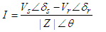 | (1) |
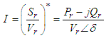 | (2) |
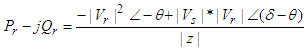 | (3) |
 | (4) |
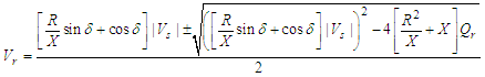 | (5) |
 | (6) |
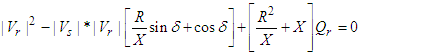
 and
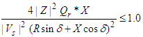
and  , by substitution (6) reduces to (7) as the FVSI.
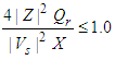 | (7) |
3. Test System and Simulation
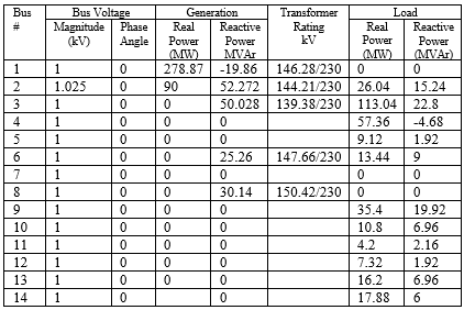
- The standard IEEE 14 bus system shown in Fig. 1 was considered and modelled in MATLAB/Simulink environment. The transmission line parameters given in per unit were converted into actual values to permit the system to be modelled in MATLAB/ Simulink environment. the half charging susceptance from line 8 to line 20 were considered as ideal, which restricted the associated transmission line length, the positive and zero sequence capacitance to be zero. In a real word power system network, it is obvious that the transmission line length between buses can never be zero. As such, a factor of (0.00005pu) was considered as line charging susceptance from line 8 to line 20 in order not to restrict the associated line length and capacitance to zero. The connected loads, generators, condensers and transformers ratings are presented in Table 1. The loads are named based on the busses they are connected to.
|
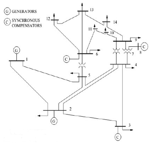 | Figure 1. IEEE 14 Bus Test System |
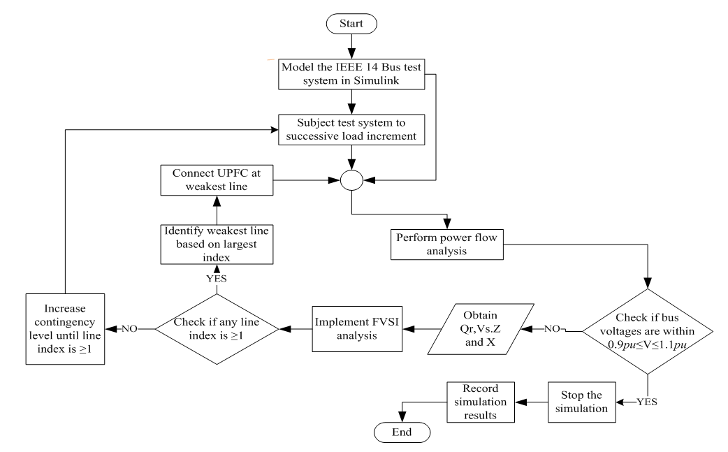 | Figure 2. Flow chart of the proposed system |
4. Result and Discussion
- The simulation results are presented to evaluate the impacts of the proposed contingency case and the UPFC on the test system. Case I: Figure 3 below shows the result for case 1. The connected loads were increased individually in steps of 20% until a bus voltage falls out of the voltage stability limit. The test system could not accommodate the anticipated 200% load increment. The subsequent increment of most of the heavy connected loads subjected the system to severe voltage collapse. Load 2, Load 6, Load 10, Load 13 and Load 14 are light loads; hence the test system was able to accommodate the respective 200% load increment. Conversely, Load 3, Load 4, and Load 9 made the test system to undergo severe voltage collapse upon further load increment of 60%, 140%, and 120% accordingly. It is seen in Figure 3 that; the respective percentage load increment of the individual connected loads made the bus voltage profiles to fall below (0.9pu).
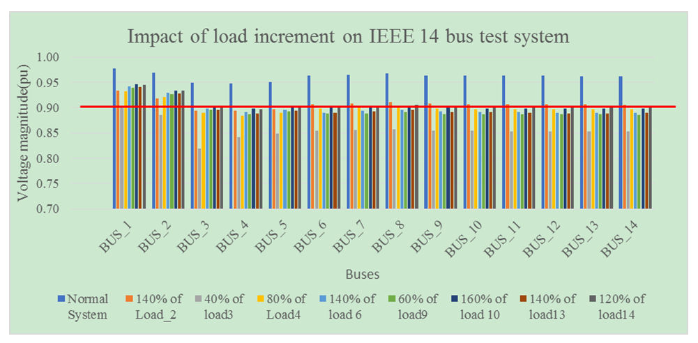 | Figure 3. Impact of sudden load change on IEEE 14 bus test system |
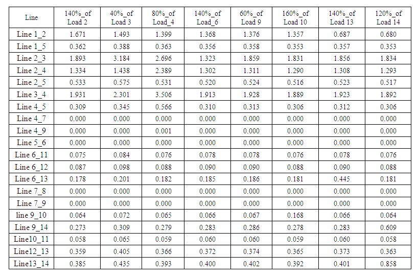 | Table 2. Result for weakest line identification using FVSI |
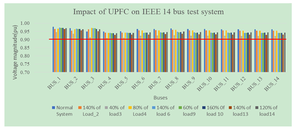 | Figure 4. Impact of UPFC on IEEE 14 bus test system |
5. Conclusions
- The aim of this study was to optimally allocate UPFC in IEEE 14 bus test systems for voltage stability improvement. The UPFC placement in the test system was predicted using FVSI as indicator. With regards to the test systems in normal operating conditions, the individual bus voltages were found to be kept within the pre-set voltage stability limit
 as expected. The test systems delivered the required power to the loads and the individual bus voltages were within the stability limit. Concerning the test systems being subjected to the successive load increment, the voltage magnitudes of most of the connected buses were below the voltage stability limit
  . The test systems experienced a substantial voltage collapse upon subsequent increment of the heavy connected loads. The FVSI analysis identified line 2_3 and line 3_4 as the optimal location for UPFC placement in the test system. Based on the results obtained, placement of the UPFC in the weakest lines aided the test systems voltage stability improvement. This was achieved by the UPFC providing the required supportive power to compensate for the voltage deficiencies. The UPFC supported the test systems with approximately 45 MVA to enhance the system's voltage stability.