-
Paper Information
- Paper Submission
-
Journal Information
- About This Journal
- Editorial Board
- Current Issue
- Archive
- Author Guidelines
- Contact Us
Electrical and Electronic Engineering
p-ISSN: 2162-9455 e-ISSN: 2162-8459
2022; 12(1): 1-12
doi:10.5923/j.eee.20221201.01
Received: Aug. 10, 2022; Accepted: Sep. 19, 2022; Published: Sep. 26, 2022

Intelligent PID Controller for Automatic Voltage Regulation
 Abstract
 Reference
 Full-Text PDF
 Full-text HTML
Abdulhamid Zaidi, Iftekhar Ibne Basith, Vajih Khan
Department of Engineering Technology, Sam Houston State University, Huntsville, TX, USA
Correspondence to: Abdulhamid Zaidi, Department of Engineering Technology, Sam Houston State University, Huntsville, TX, USA.
| Email: |  |
Copyright © 2022 The Author(s). Published by Scientific & Academic Publishing.
This work is licensed under the Creative Commons Attribution International License (CC BY).
http://creativecommons.org/licenses/by/4.0/

A well-behaved electric power system requires both the frequency and voltage to remain at standard values during the operation. The active power and reactive power balance should be maintained between the generation and utilization of the AC power. Any change in the supplied voltage from its rated value may damage the components that are connected in the electric power network since they are designed to operate at a certain rated voltage. Keeping the generator terminal voltage at a rated value is done through the field current in the generator exciter. A Proportional-Integral-Derivative (PID) controller has been used in the Automatic Voltage Regulator (AVR) system to keep the voltage approximately at the rated value. Several solutions were proposed on how to tune the PID gains, including the classical Ziegler and Nichols methods. In this paper, we adopt three methods to tune the parameters of the PID controller. Neural networks based online tuning, Particle Swarm Optimization (PSO) based offline tuning and Water Cycle Algorithm (WCA) based offline tuning. The three tuning methods are applied for a single power area system. Two types of IEEE recommended standard excitation system models, DC2A and AC4A, are considered. The three proposed tuning methods are compared with each other in terms of the overshoot, undershoot and settling time. All of them show good performance, while the PID controller tuned by WCA provides superior performance in terms of the overshoot and settling time against any voltage deviation compared to the other two methods.
Keywords: Proportional-Integral-Derivative (PID), Automatic Voltage Regulator (AVR), Particle Swarm Optimization (PSO), Water Cycle Algorithm (WCA), Neural Network (NN)
Cite this paper: Abdulhamid Zaidi, Iftekhar Ibne Basith, Vajih Khan, Intelligent PID Controller for Automatic Voltage Regulation, Electrical and Electronic Engineering, Vol. 12 No. 1, 2022, pp. 1-12. doi: 10.5923/j.eee.20221201.01.
Article Outline
1. Introduction
- Keeping the voltage in a power grid at its rated value is a big challenge. The instability of the terminal voltage may lead to losses in the reactive power and in the real line [1]. Also, the deviation of the terminal volt from its rated volt will affect all the equipment connected to the grid and may reduce its performance and life span [2]. Hence, the Automatic Voltage Regulator (AVR) needs to be applied to prevent the terminal volt deviation, improve voltage stability, and control the reactive power [3]. The AVR dynamic responses such as the rise time, overshoot and the steady state error of terminal volt are the control objectives for a better system performance. A controller is generally added into the AVR system to get the desired response and improve the robustness of the AVR against any dynamic parameter change or system disturbance [4]. So far, many control strategies such as adaptive control and optimal control have been proposed for AVR. A fixed gain proportional, integral, and derivative (PID) controller is widely used due to its simplicity and success in many industrial applications. The PID controller parameters are normally tuned based on trial and error. However, the system generally shows poor dynamic response if the system parameters change with time and the PID parameters need to be re-tuned [5]. Furthermore, the uncertainties and nonlinearities of power grids make the tuning of PID parameters more difficult. Several metaheuristic optimization tuning methods such as genetic algorithms (GA) and differential evolution (DE) algorithms have been proposed to attain the optimal gains of the PID [6,7]. However, these methods are time consuming and the dynamic response of the AVR system is usually still poor based on recent studies. A Neural network-based controller, Narma-L2, has been proposed to approximate the model of the AVR. However, this method may not guarantee a good performance subject to the system parameter changes or system disturbance due to approximation [8]. To overcome the previously mentioned problems, three methods have been developed here to optimize the PID controller gains. The first method is used to tune the gains in real time based on neural networks, while the Particle Swarm Optimization (PSO) and Water Cycle Algorithm (WCA) are used to tune the PID gains offline. The main goal of this paper is to examine the voltage instability problem for the AVR system connected to a generator in a synchronous machine, taking into consideration the type of excitation system that is used to excite the generator. The operation conditions and load changes of the grid are examined. The three proposed controllers are simulated and tested in Matlab/Simulink. Comparisons of the three proposed controllers are conducted to show their effectiveness on the AVR terminal volt.The main contribution of this paper is to apply intelligent PID controllers to the AVR system to achieve a desired performance including acceptable dynamic responses over various system parameter changes. Using Neural Networks as a real time tuning method, Water Cycle Algorithms and Particle Swarm Optimization as offline tuning methods in the intelligent PID controller, we achieve AVR system improvements in the overshoot, delay in settling time as well as the steady state error over the other PID tuning methods.The rest of paper is organized as follows. In Section 2, the model of the automatic voltage regulator is provided. In Section 3, the PID controller design based on the three proposed methods are explained. Simulation and discussion of the results are presented in Section 4. Section 5 provides conclusions and directions for future work.
2. Automatic Voltage Regulator Modelling
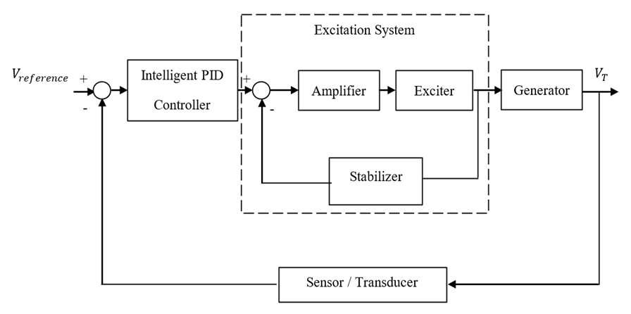
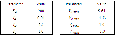
- The Automatic Voltage Regulator generally consists of four main components: amplifier, exciter, generator, and sensor as shown in Figure 1. The amplifier computes the error between the rated volt (V Reference) and terminal volt (VT) and amplifies it for the exciter. The excitation system is the heart of the AVR system. Exciter supplies a direct current to the generator field winding of the synchronous machine. Also, through the exciter, we can control the flow of the reactive power and hence control the volt. The sensor senses the terminal volt and converts the AC to a DC form to compare it with the reference volt. An excitation system can be classified into DC, AC and Static excitation system. Many excitation models have been standardized in block diagram representations by the IEEE [9]. Two types of IEEE excitation system standards from the AC and DC exciters family are considered in this paper. The DC2A and AC4A exciters are chosen for the sake of simplicity to simulate them in the system.
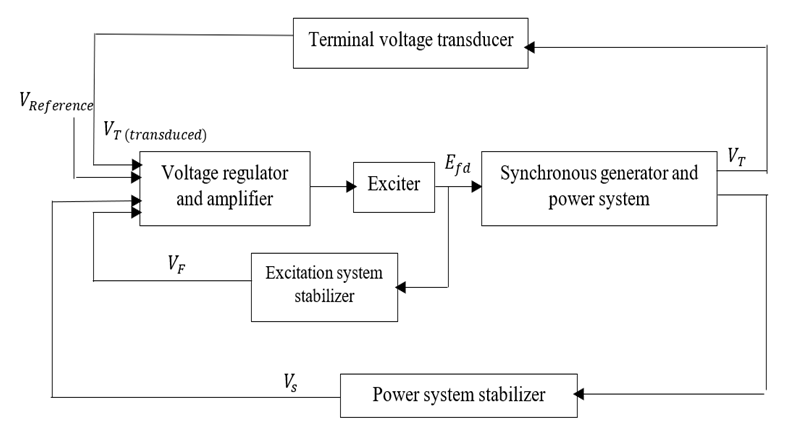 | Figure 1. The block diagram of AVR with an exciter [9] |
2.1. IEEE Excitation System Type DC2A
- This type of exciter supplies a DC current to the field winding. The block diagram of a DC2A exciter is shown in Figure 2. The terminal volt (VT) is sensed and subtracted from the set point voltage (V Reference). The (Vs) of the power system stabilizer is considered to be zero during the steady state operation. The error signal is fed to the exciter to produce the required field voltage (EFD).
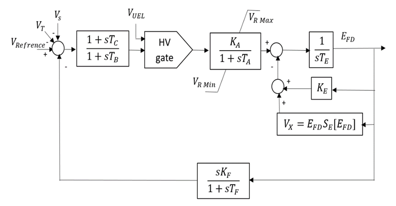 | Figure 2. The block diagram of a DC2A exciter [9] |
2.2. IEEE Excitation System type AC4A
- Figure 3 shows the block diagram of the type AC4A exciter system. In this type, a small alternator mounted on the shaft and is used as a voltage source. The output of this exciter is rectified to form a DC voltage. The voltage regulator regulates the field of the AC exciter and regulates the field of the main alternator.
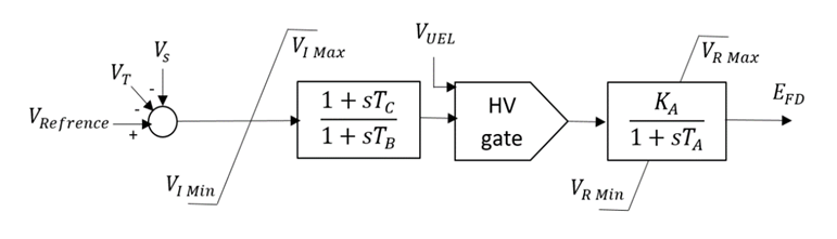 | Figure 3. The block diagram of an AC4A exciter [9] |
3. Proposed PID Controllers
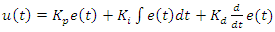
- A PID or PI controller can be used to solve the voltage deviation problem in the AVR system. The controller can provide a control signal designed for specific excitation requirements. The response of the controller can be characterized in terms of the responsiveness of the controller to the error. Application of the PID controller involves choosing KP, Ki and KD that provide satisfactory closed-loop performance. These parameters should be selected so that the characteristic response speed, settling time and proper overshoot rate, are minimized to guarantee the system stability. The proportional term KP produces an output value that is proportional to the current error, the integral term Ki accelerates the movement of the system output towards the setpoint and eliminates the residual steady-state error that occurs with a pure proportional controller, and the derivative action KD predicts the system behaviour and thus improves the settling time and the stability of the system. Figure 4 shows the general block diagram of a PID controller. The dynamic model of the controller is as follows
 | (1) |
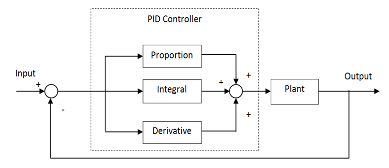 | Figure 4. The block diagram of a PID controller [10] |
 | (2) |
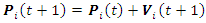
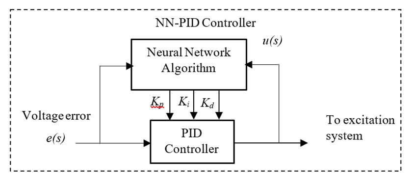
3.1. PID Controller Based on Neural Network (NN-PID)
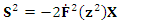
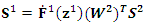
- A fixed gain PID controller is commonly used because its structure is simple, and it is easy to implement [10] [11]. However, this method has a few limitations. If the controlled plant parameters change over time, the PID controller could hardly handle the changing environment. Hence, the neural network based online method is adopted here to tune the PID controller gains [12] for the AVR system in a synchronous machine. The ability of the neural network to approximate a nonlinear function with at least one hidden layer as reported in [13]. In this paper, we apply the neural network to adjust the PID controller gains online, namely NNPID. The tuning of controller gains is done by propagating the voltage error between V reference and VT on a two-layer neural network at each sampling time which can be specified by the user taking into consideration the time for the neural network algorithm to update the PID gains. In this method, the neural network coefficients (weights and biases) are modified at each sampling time to regulate the PID parameters to achieve the smallest error between V reference and VT. The two-layer network shown in Figure 5 has 4 nodes for the inputs in the form of (3) - (6), 3 nodes for the outputs representing the PID gains and 8 nodes in the hidden layer. The neural network activation functions f1 and f2 are in (7) and (8).
 | (3) |
 | (4) |
 | (5) |
 | (6) |
 | (7) |
 | (8) |
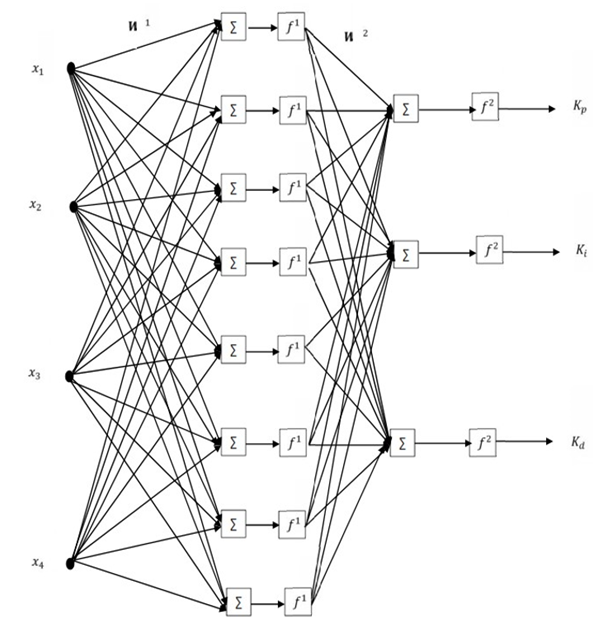 | Figure 5. A two-layer Neural Network architecture |
 | (9) |
 | (10) |
 | (11) |
|
3.2. PID Controller Based on Particle Swarm Optimization (PSO-PID)
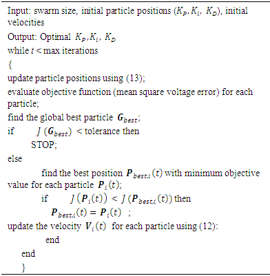
- Particle Swarm Optimization (PSO) is an optimization algorithm introduced by Kennedy and Eberhart in 1995 [14]. The PSO methodology is considered as a very powerful technique to optimize nonlinear functions and nowadays is used in many applications [15]. The main concept of PSO was drawn to emulate the social behavior of a school of fish or a flock of birds when seeking food. The PSO theory is based on the movement of intelligent swarms to find the optimum solution of optimization problems [14]. The PSO technique obtains the best solution (candidate) inside the population. The optimum solution is obtained by updating particle locations after being assigned random initial locations [15]. In this paper, the particles are the PID controller gains. Each particle position (P) represents the Kp, Ki and Kd values. The position of each particle (controller gains) is updated at each iteration by minimizing the mean square voltage error (9) for the whole simulation time.The steps for updating the particle positions are shown as follows and summarized in Algorithm 2
 | (12) |
 | (13) |
 The velocity vector
 The position of particle
 The personal best position
 The global personal best
 and
and  : The positive acceleration constant
|
3.3. PID Controller Based on Water Cycle Algorithm (WCA-PID)
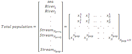
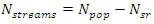
- The Water Cycle Algorithm (WCA) is an algorithm introduced by Eskander and Sadollah in 2012 to solve unconstrained and constrained optimization engineering problems [16]. The algorithm is considered as a powerful metaheuristic optimization method to find the global optimum solution for convex and nonconvex functions [17]. The main concept of WCA was to emulate the cycle and movement of water under and above the earth surface [18]. In nature, the sea is considered as the most downhill place where the water ends up and stays. The sea consumes the water from the rivers and streams and the streams flow into the rivers. In this method, the sea is defined as the global optimum solution. The rivers and streams are defined as the individual solutions. The matrix in (14) is randomly generated and represents the sea, rivers and streams
 | (14) |
 is the population size. The cost function of each stream and river is given bellow,
 | (15) |
 specified by the user,
 | (16) |
 | (17) |
 given by,
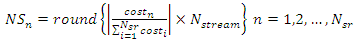 | (18) |
 | (19) |
 | (20) |
 and t is the iteration steps.Figure 6 shows the schematic view of the streams movements.
 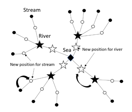 | Figure 6. Schematic drawing for WCA movement [16] |
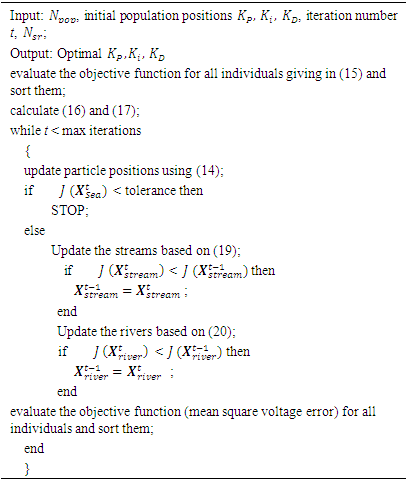
 represents the three gains Kp, Ki and Kd values. The objective here is to minimize the mean square voltage error between Vreference and VT in (2) for the whole simulation. The steps for updating each stream and river are illustrated in Algorithm 3.
|
4. Simulations and Results
- The PID controller applied to the AVR system is shown in Figure 7. In order to demonstrate the response of the AVR with the proposed controllers, the three algorithms are coded in Matlab and linked to the AVR system which is built in Simulink. As in any metaheuristic optimization problem, the population size and convergence criterion need to be chosen carefully. The population size for the PSO is chosen to be 50 while that for the WCA is 40. In the NN-PID algorithm, the number of neural network layers, weights and biases are chosen as mentioned in Section 3.1. The stopping criterion for all the algorithms is chosen to be

 | Figure 7. The block diagram of the AVR system with a PID controller [5] |
|
|
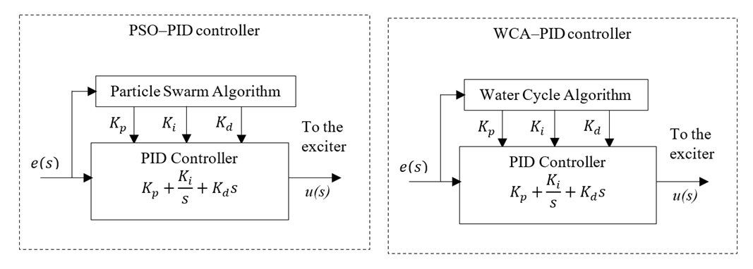 | Figure 8. The block diagram of a PID controller with PSO and WCA |
 | Figure 9. The block diagram of a PID controller based on neural network |
4.1. AVR Responses with the DC2A Exciter
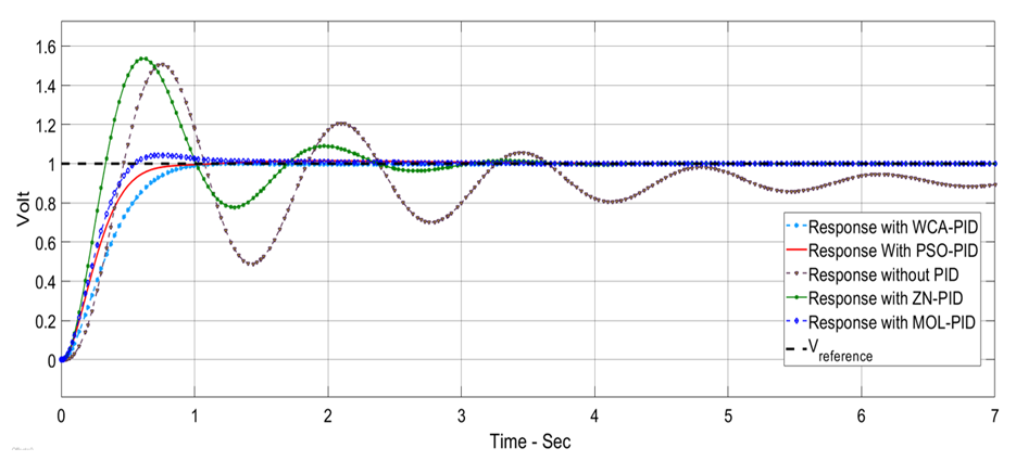
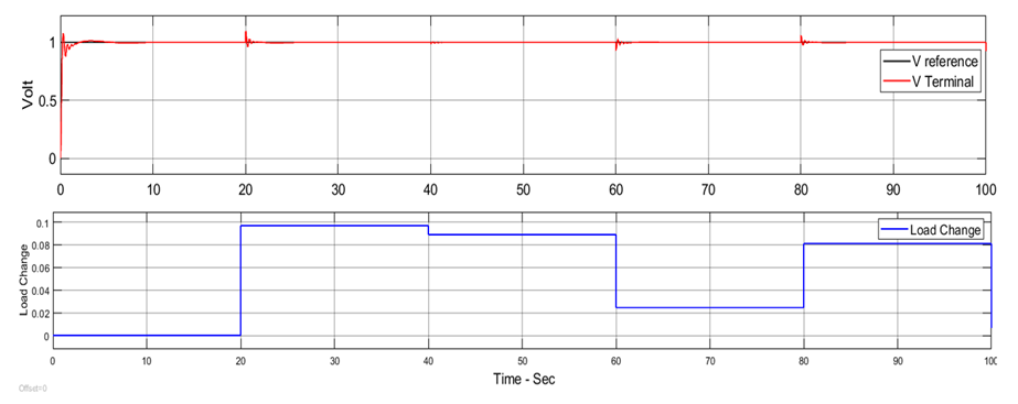
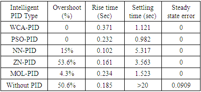
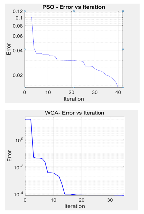
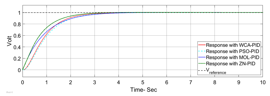
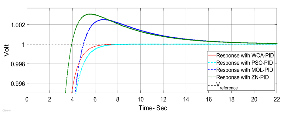
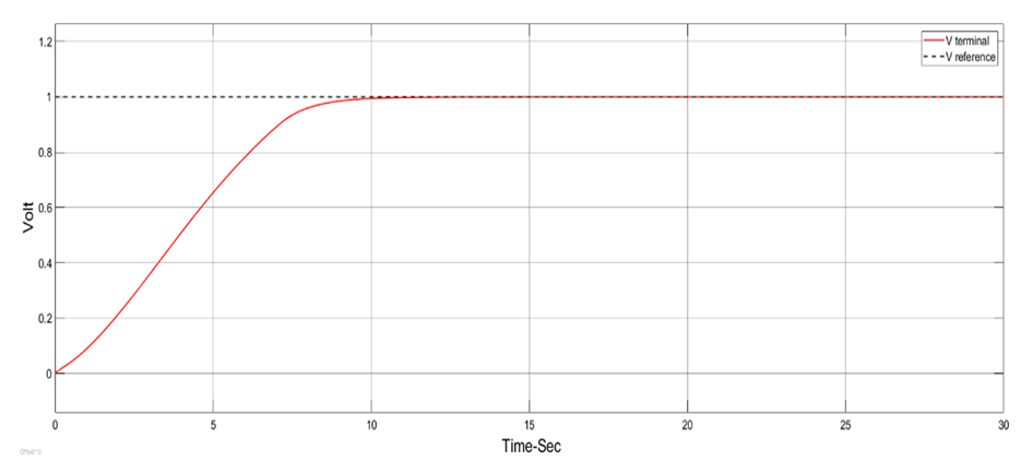
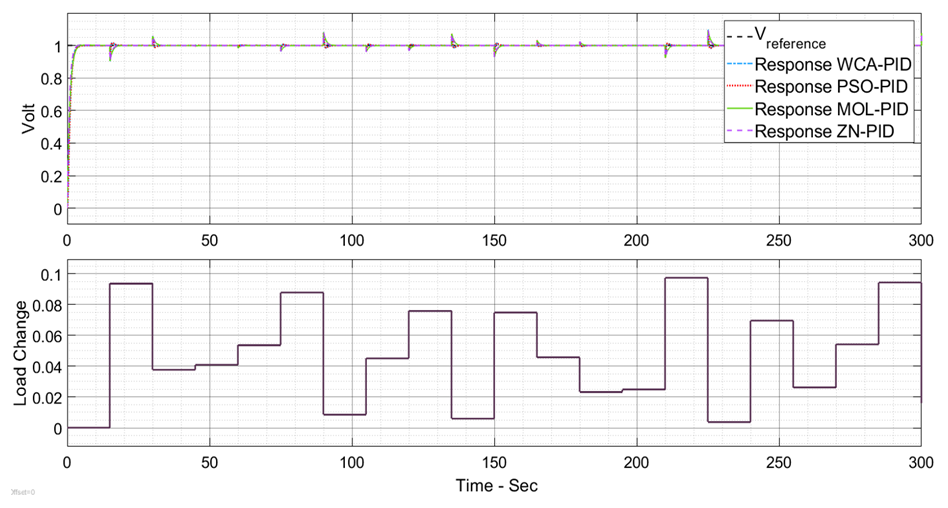
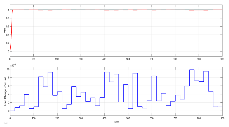
- DC2A AVR system responses are shown in Figures 10 to 16 for the three proposed controllers. Firstly, Figure 10 shows that the PSO-PID algorithm starts to converge by the fifth iteration while the WCA-PID algorithm converges by the tenth iteration. The two algorithms run for more than 40 iterations to obtain a smaller voltage deviation with the smallest damping. In the NN-PID case, the system voltage error reduces at each sampling time. Secondly, the voltage deviation of using the three controllers are shown in Figures 11 and 13. The overshoot, settling time and system response speed are greatly reduced by applying the optimized controllers using the WCA and PSO compared to the NN-PID. From Table 3, there is no overshoot in the AVR response with the PSO-PID and WCA-PID while in Many Optimizing Liaisons PID (MOL-PID) and Ziegler Nichols PID (ZN-PID) the overshoot is 4.3% and 53.6%, respectively [19], in NN-PID, the overshoot is about 15% higher than that of PSO-PID and WCA-PID, but still does much better than ZN-PID. The rise time of the AVR response of the three proposed controllers is between 0.102 sec and 0.371 sec. This range of rising time is considered as fast enough for the AVR terminal volt to rise. Regarding the settling time, PSO-PID controller and WCA-PID push the terminal volt of the AVR system to settle in less than 1.2 sec which makes them the fastest two controllers to settle compared to NN-PID and ZN-PID. The NN-PID controller is slower to settle because this controller works online and its settling time depends on the sampling time. Thirdly, the robustness of the DC2A AVR system with the three proposed controllers is superior as all the three controllers could maintain the terminal volt for a range of 0% to 10% random load change as shown in Figures 14, 15 and 16.
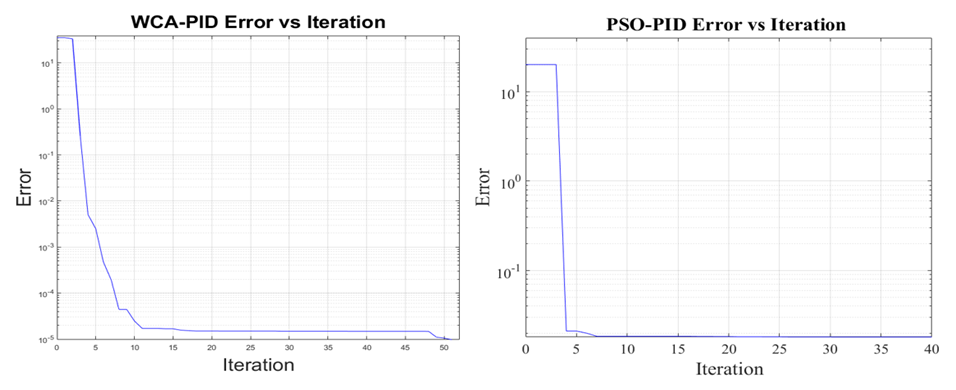 | Figure 10. The convergence of the WCA-PID and PSO-PID algorithms for the DC2A AVR system |
 | Figure 11. AVR response with exciter DC2A in the case of no load change |
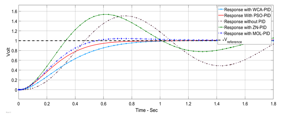 | Figure 12. AVR overshoot response with DC2A exciter in the case of no change in the load |
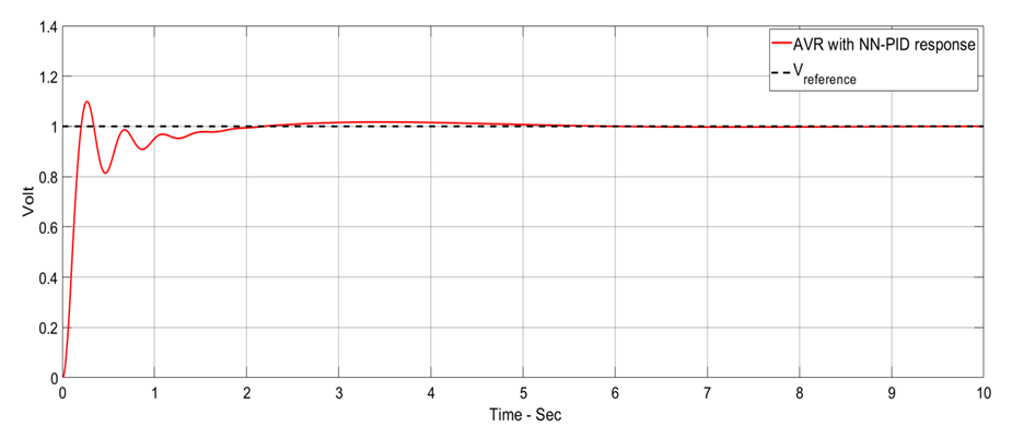 | Figure 13. AVR response with exciter DC2A with the NN-PID controller in the case of no load change |
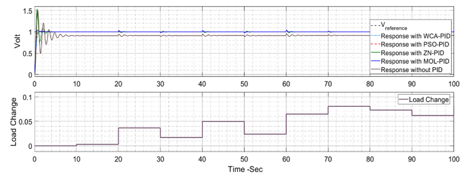 | Figure 14. AVR response with exciter DC2A with up to 10% random load change |
 | Figure 15. AVR response with exciter DC2A with up to 10% random load change zoom in |
 | Figure 16. AVR response with exciter DC2A with up to 10% random load change for the NN-PID controller |
4.2. AVR Response with the AC4A Exciter
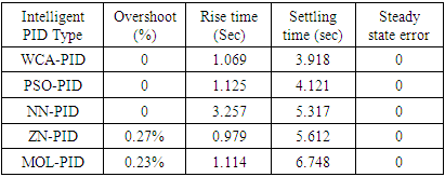
- The PSO-PID and WCA-PID algorithms for an AVR system with the AC4A exciter take longer time to converge compared to the AVR with the DC2A exciter. PSO-PID converges at the 40th iteration while WCA-PID converges at about the 14th iteration as shown in Figure 17. The three proposed controllers are compared to each other and to the AC4A AVR system with ZN-PID and MOL-PID. The three proposed controllers show good performance in general. The system steady state error (ess) is about zero for all the three controllers. The results are shown in Figures 18 to 20 and Table 4. The observation is that the ZN-PID and MOL-PID [19] have small overshoot (0.25% and 0.22%, respectively), while that of the three proposed controllers is very small (near 0%). The terminal volt for the AC4A AVR with PSO-PID and WCA-PID takes a bit longer to rise than that of ZN-PID [19]. The range is from 1 sec to 1.3 sec while in the system with NN-PID it is about 3.257 sec. The settling time is remarkable with PSO-PID and WCA-PID, which are 3.918 sec and 4.121sec respectively as compared to 6.748 sec of MOL-PID. The AC4A AVR system with all the three controllers is robust against the disturbance or load change as shown in Figures 21 and 22.
|
|
 | Figure 17. The convergence of the WCA-PID and PSO-PID algorithms for the AC4A AVR system |
 | Figure 18. AVR response with AC4A exciter in the case of no change in load |
 | Figure 19. AVR response with AC4A exciter showing the system the overshoot of ZN-PID and MOL-PID |
 | Figure 20. AVR response with AC4A exciter with no load change for the NN-PID controller |
 | Figure 21. AVR response with DC2A exciter with up to 10% random load change |
 | Figure 22. AVR response with AC4A exciter with random load change for the NN-PID controller |
 in (12) provides a memory of the previous iteration. If the new location based on
  is not optimum with regard to the previous location, the new location is ignored. This makes sure that the PSO algorithm gives no worse solution for each particle in each Iteration. NN has poorer performance among the three proposed controllers despite that it is an online tuning method. This is because it is gradient-based and the step size α is pre-selected [20], which may provide local optimum solutions.
5. Conclusions
- In this paper, the water cycle algorithm, particle swarm optimization and neural network are used to tune the gains of a PID controller for automatic voltage regulation in two types of IEEE recommended excitation systems. The proposed WCA-PID, PSO-PID and NN-PID controllers are tested with load disturbances. through the simulations, the system performance is evaluated in terms of dynamic response parameters, i.e., settling time, rise time and overshoot. It is concluded that the system based on the proposed controllers tuned by WCA, PSO or NN has a good transient response and is robust to change in the load. As a further study, the proposed controller can be used with the other IEEE recommended exciters. Furthermore, the under excitation and over excitation cases and their effect on the control of the AVR system are not studied in this paper. It will be reasonable to include them to get more practical response results.