Sarhan Hasan1, Salah Eddin Altaher Albakoush2, Mawloud Jummah Mawloud Albakoush3
1University of Denver, Colorado, USA
2Om Alrrabea Faculity of Sciences and Technology, Surman, Libya
3University of Zawia, Faculity of Engineering Zawia, Zawia, Libya
Correspondence to: Sarhan Hasan, University of Denver, Colorado, USA.
| Email: |  |
Copyright © 2020 The Author(s). Published by Scientific & Academic Publishing.
This work is licensed under the Creative Commons Attribution International License (CC BY).
http://creativecommons.org/licenses/by/4.0/

Abstract
The large number of distribution transformers through an electrical network in any country results in a significant amount of losses. Low efficiency transformer effects the environment by requiring increased generation to supply increase transformer losses. The wasted generation causes increased carbon dioxide in the air and contributes to so called greenhouse effect. Alternatively, energy efficient transformers like amorphous transformers (AMTD) reduce the required generation and reduce the emission into the air. The purpose of this paper is to introduce amorphous material as an alternative transformer core material in place of traditional silicon steel core. as it has excellent magmatic characteristics compared to silicon steel material. By using amorphous as a transformer core 70% percent of transformer no load losses could be reduced compared to the traditional transformer, and that is due to amorphous low thickness and its high resistivity. The Total Owing Cost of Both Transforms Amorphous and Silicon Steel determines which one is appropriate for installation and operation through the electrical network. The Total Owing Cost (TOC) of any transformer is the bed price levelized over the life of the transformer plus the cost of future transformer losses (no load losses and load losses) discounted to present value and levelized over the life of the transformer. The distribution office in ministry of electricity in al zawiya region, Northwest of Libya plans to replace about 2,009 distribution transformers in the period between 2017 and 2018 in The Zawiya region in Northwest of Libya, and this is considered as a case study in this paper where the energy and money saving, and the reduction in CO2 emissions using amorphous transformer are determined.
Keywords:
Amorphous, Owing Cost, Silcon Steel
Cite this paper: Sarhan Hasan, Salah Eddin Altaher Albakoush, Mawloud Jummah Mawloud Albakoush, Amorphous Transformer Saving, Electrical and Electronic Engineering, Vol. 10 No. 2, 2020, pp. 23-26. doi: 10.5923/j.eee.20201002.01.
1. Introduction
The amorphous metal is not crystalline like silicon steel. The atoms in amorphous metal are arranged in a different pattern than those in silicon steel. This can be illustrated in the diagram shown in Fig.1a, b [1]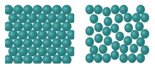 | Figure 1. a. Crystalline Silicon Steel, b. Non-Crystalline Amorphous Metal |
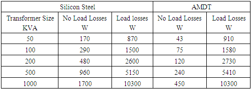
The randomness of the molecular structure of amorphous metal causes less fraction than silicon steel when a magnetic field is applied, so this results in the reduction of hysteresis losses in amorphous transformer that leads it to have more significant reduction in no load losses than silicon steel core transformer [1]. The very thin nature of amorphous metal lamination makes it have lower eddy current losses than silicon steel core transformer. Thin laminations result in low resistance between laminations and low eddy current losses. The combinations of reduced hysteresis and eddy current losses results in new transformers that use amorphous metal in their core which lose 70 to 80 percent less energy in their core than silicon steel core transformers [2] Table.1 shows no load losses and load losses for amorphous transformer and silicon steel transformer for different sizes. Fig.2 illustrates the performance of amorphous and silicon steel for 1000 KVA impressed oil transformer. It’s clearly that the AMT transformer efficiency is higher than that for silicon steel at different load currents. Using amorphous transformer results in power saving for each size as illustrated in Fig.3. Table 1. No Load Losses and Load Losses for Amorphous and silicon Steel Transformer
 |
| |
|
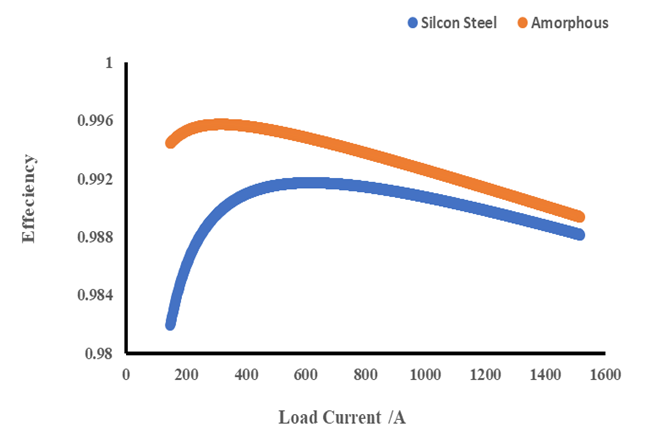 | Figure 2. AMT And Silicon Steel transformer Performance 1000KVA |
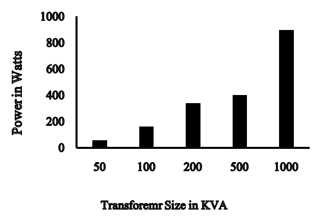 | Figure 3. Power Saving Due to No Load Losses for each transformer size |
2. Model Outline and Formulation Transformer Present Worth Calculation
In transformer economic analyses, the initial cost of the transformer does not determine its acceptance to installation and operation through electric networks, but transformer life cost or total owning cost (TOC) determines its acceptance. Total owing cost considers the future cost of transformer losses in addition to initial cost. The present worth concept is based on the fact that money today has a different value than it will have in the future. There are two present worth analyses factors: single present worth factor (SPW) and uniform series present-worth (USPW) factor. Equation (1) illustrates the formula of single present worth factor [3].  | (1) |
Where n= number of periodsi= the rate of return or discount factor in percent of year.It is used to determine the present worth of a future amount F discounted to the present worth P that is described by the following formula: | (2) |
The second type of present worth analyses deals with converting equal annual costs into present worth. The single payment present worth method requires multiplying the present worth factor for each year by the annual cost of that year. There is a factor called present worth factor for a uniform series that is illustrated in equation (3) that allows to multiplication the annual cost by the uniform series present worth of the annual cost.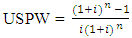 | (3) |
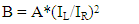
This factor is used to calculate the capitalized cost of losses in transformer per Kwatt for both No load losses and load losses (A&B factors). Total owning cost (TOC) = Initial Price + A*(no load losses) + B*(load losses)Cost of no load = A*(no load losses)Cost of load losses = B*(load losses)Where A is the capitalized cost per rated watt of no load loss.B is the capitalized cost per rated watt of load loss.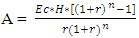 | (4) |
 | (5) |
Where EC = Cost of Energy (cent/kwh).EC is the levelized annual cost per Kilowatt-hour of fuel, including inflation, escalation, and any other fuel related components of operation or maintenance costs that are proportional to the energy output of the generating units. H = Number of Hours of operation per yearr = rate of interestn = number of operation years of a transformerIL = Loading Current.IR = Rated Current.
3. Case Study and Results
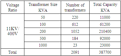
Based on the plan of the distribution office in the electric company in the al zawiya region, Northwest of Libya, about two thousand silicon steel distribution transformers will be replaced during the period from 2017 to 2018 because most of them have been in service for more than 30 years [4]. Table.2 and fig.5 show the number of each size that required to replace, and fig.4 shows the Zawiya region on Libyan map. Table 2. Number of transformers for each size required for replacement
 |
| |
|
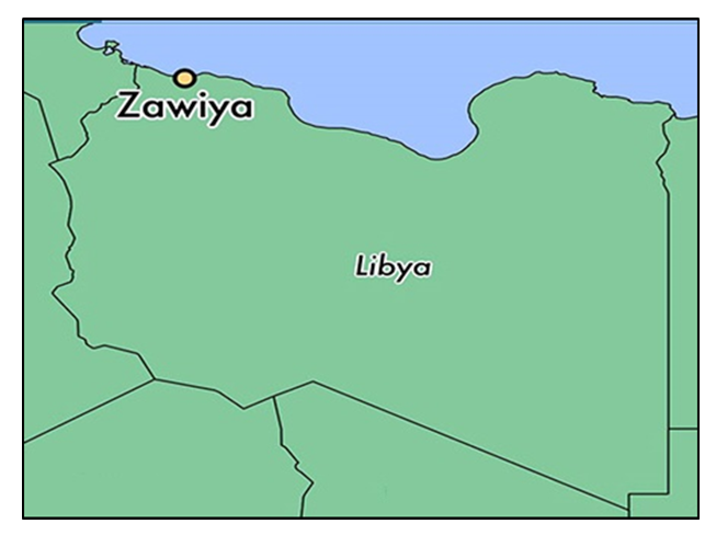 | Figure 4. Zawiya Region in Libya map |
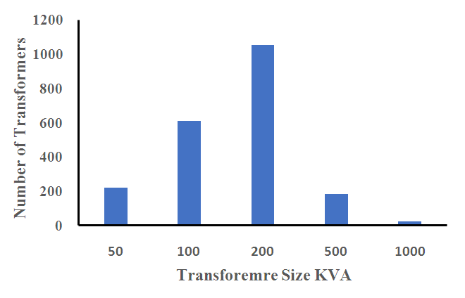 | Figure 5. Number of silicon steel transformers required to replace in Zawiya Region |
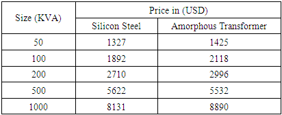
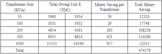
Table 3 shows the prices of both silicon steel and amorphous transformers for different sizes [5] [6]. By applying equations 3,4,5, the total owing cost for each transformer is determined for 25 years, and power saving could be calculated as illustrated in Table.5 & 6. The no load losses of the transformer is constant during the transformer operation life while load losses is variable and dependent on load factor, and equation 6 clarifies that. The load factor of all transformers is considered equal to 0.6 in this study. Load Losses = Full load losses *(Load Factor)2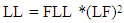 | (6) |
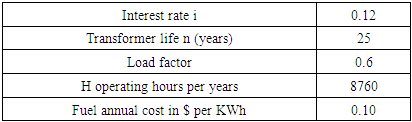
The losses consumed by either silicon steel or amorphous transformer per year for each size at operated load factor is calculated, and Table.4 shows the study Parameters [7].Total losses = No Load Losses + Load Losses.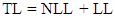 | (7) |
Based on equations 4,5 and data on table.4,5, the capitalized factors (A, B) could be calculated.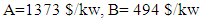 Reduction of transformer losses by using AMT helps to reduce CO2 emissions. The emission coefficient of Carbon Dioxide is about 0.444 kg-CO2 /kWh [8].
 Table 3. Transformers Prices
 |
| |
|
Table 4. Study Parameters
 |
| |
|
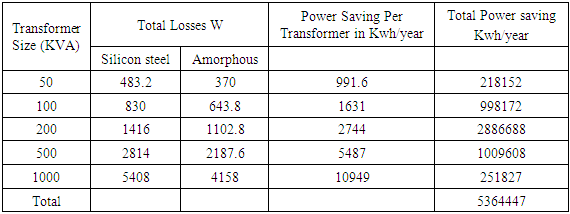
Table 5. Total Losses for All Sizes for Both Silicon Steel and Amorphous Transformer
 |
| |
|
Table 6. Total owing cost and money saving
 |
| |
|
4. Conclusions
The purchase of a higher cost, higher efficiency transformer instead of a lower cost low efficiency transformer will result in significant saving over the whole life of a transformer. The distribution office in General Electrical Company in Libya should replace 2,009 distribution transformers in Al zawiya Region in Northwest of Libya with amorphous transformers where 5.364447 Gwh will be saved each year, $ 474579 will be gained, and 2381.814 tons of CO2 will be reduced each year.
Nomenclature
References
| [1] | Energy Efficient Transformer Barry W. Kennedy 1998. |
| [2] | P. M. Curran “Metglas Alloy for Distribution Transformer Cover”, July 26, 1988, IEEE Power Engineering Society Meeting. |
| [3] | Hao Wen and Hvi Zov,” Exploration on Energy Saving effect of amorphous transformers extended in Nanning based on theoretical analyses and total owning cost methods (TOC)”, Distributed power generation and integration technology, CICED2008. |
| [4] | The Distribution Office of General Company of Ministry of Energy of Libya 2017. |
| [5] | http://www.mccb.cn/english/ |
| [6] | http://jbgroup.en.alibaba.com/ |
| [7] | Economical study Office in General Electrical Company of Libya. |
| [8] | www.hitachi.com/environment/products/trans/index.html |

 Abstract
 Reference
 Full-Text PDF
 Full-text HTML