Okelola M. O., Ojo S. I.
Electronic and Electrical Engineering Department, Ladoke Akintola University of Technology, Ogbomoso, Nigeria
Correspondence to: Ojo S. I., Electronic and Electrical Engineering Department, Ladoke Akintola University of Technology, Ogbomoso, Nigeria.
| Email: |  |
Copyright © 2020 The Author(s). Published by Scientific & Academic Publishing.
This work is licensed under the Creative Commons Attribution International License (CC BY).
http://creativecommons.org/licenses/by/4.0/

Abstract
Solar powered inverter is of paramount importance in the developing country most especially in Nigeria due to geometric progression of the nation’s population that posed a serious threat to the insufficient supply of clean and continuous electricity thereby affecting the economic progress of the country. Short Message Service (SMS) controlled solar powered inverter constructed to solve the problem of power epileptic suffered from signal fluctuation due to obstruction along propagation path. Hence, this paper aimed to enhance SMS controlled solar powered inverter for residential, commercial and industrial used. The battery bank supply 24V to the Oscillator via a voltage regulator which is used to generate a desired frequency of 50Hz at each of the output. The output of the oscillator stage is fed to the buffer amplifier stage to drive the base current of the bipolar junction transistor which amplifies the signal to the power switching stage. The enhanced system consists of MRC, GSM module and solar power inverter. MRC combined the received faded signals through the Rayleigh fading channel and output of MRC serves as input to GSM module to decode the information whether to switch inverter ON or OFF through relay connected in series with inverter switch. The performance of the system was measured using signal strength at input of GSM module. The results showed that enhanced system gives higher signal strength when compared with conventional system and this is due to combining nature of the received signals before applied GSM module.
Keywords:
Solar Powered Inverter Solar Panel, Renewable Energy, MRC, GSM module, Signal strength, Short Message Service (SMS)
Cite this paper: Okelola M. O., Ojo S. I., Enhancement of SMS Controlled Solar Powered Inverter over Multipath Fading Channel Using Maximal Ratio Combiner (MRC), Electrical and Electronic Engineering, Vol. 10 No. 1, 2020, pp. 7-14. doi: 10.5923/j.eee.20201001.02.
1. Introduction
Electricity supply is one of the infrastructural facilities that are indispensable to a nation’s economic development. The efficiency of electricity supply will not only influence returns on existing enterprises but also plays a major role in creating environment that influence potential investment. In this our contemporary world, almost every activity makes use of electrical and electronic device, whether for general household or industrial use. The operation of these devices requires continuous supply of electrical power, to enhance the efficient delivery of power to these devices. In developed countries, the power supply is of good quality and is highly reliable without any problems. However, in developing countries like Nigeria there appear to be problems associated with provision of power supply by electricity companies including power outage. The Power supply problems are experienced more during the dry season and also, the effect of thunderstorm during the raining season affect power supply. The rapid increase in the nation’s population has posed a serious threat to the power supply affecting economic progress of a nation. This problem arises because of the consumption of power which is growing faster compared to the power generation. Many researchers have worked very hard to solve this problem by designed a standby generator but at expense of excessive noise, air pollution which is hazardous to the environment. These lead some researchers to design and constructing an uninterrupted power supply popularly known as inverter [1,3,5]. In recent times, technology has given way to derive energy from sunlight through solar panel and convert it to Alternating Current (AC) with the help of power inverter. Since the utility company cannot provide uninterrupted power needed at present, an alternative source of power using an inverter with solar backup is most appropriate. An inverter is a device that convert Direct Current (DC) power source to Alternating Current (AC) at a desired output voltage and frequency. Inverter makes use of one or more batteries in conjunction with electronic circuit to convert the DC supply of the battery into AC power supply required by most of the electrical and electronic devices. An inverter typically consists of inverting circuit (which made up of oscillator, buffer amplifier, transformer and MOSFET circuit), a charging circuit and automatic change-over [2]. However, most of the inverter constructed lack communication at a distance such as ON and OFF, to know the battery status as well as inverter status at a particular time. In 2018, [1] also designed and constructed a Short Message Services (SMS) to communicate with the inverter system at any distance in order to solve the problem of lack of communication. In their work, the user of inverter can send message to and receive message from the inverter. But the system suffers from receiver sensitivity due to multiple copies of the received signal resulted from obstruction along propagation path such as tall buildings, trees and valleys. The resulting effect of multipath propagation is variation of the received signal due to different path having different angles of arrival and time thereby causing reduction in signal strength below receiver sensitivity [3]. When the signal strength is below the receiver sensitivity, the message sent to the inverter will not be delivered and the communication will be disrupted. When this happened, the user of inverter will need to send another message and continue the process until the desired information is gotten from the system. This problem makes the work of [1] to lack reliability. Therefore, this paper evaluates performance of an improved SMS control to solve the problem of lack of reliability using Maximum Ratio Combiner (MRC).
2. Renewable Energy Sources
Renewable energy is a source of energy that comes from natural sources such as sunlight, wind, geothermal and so on. It is a form of energy which are naturally replenished, that is energy that can be replaced overtime by natural process. Renewable energy resources are sources of power that quickly replenish themselves and can be used again and again. Not only will renewable energy sources not run out, but they also generate clean energy which does not release greenhouse gas emissions in the process. True renewable energy sources are energy supplies that are refilled by natural processes at least as fast as they are been used. All renewable energy comes, ultimately, from the sun and it can be used directly as in solar heating systems or indirectly as in hydroelectric power, wind power, and power from biomass fuels. Renewable energy supplies can become exhausted if it is used faster than they become replenished. However, if it is use wisely, renewable energy supplies can last forever. Renewables energy can be used to generate electricity, heat or sometimes both. The most common use of renewable energy sources is to produce electricity. There are several renewable energy sources that are in use today such as hydropower, solar energy and wind power [3].
2.1. Hydropower
Hydropower represents one of the oldest and largest renewable power sources and accounts for close to ten percent of our nation’s electricity. Hydropower plants convert the energy of flowing water into electricity. This is primarily done by damming rivers to create large reservoirs and then releasing water through turbines to produce electricity. Hydropower results in no emissions into the atmosphere but a damming river can overflow resulting in flood in the area surrounding hydropower station [1].
2.2. Solar Energy
Solar energy come directly from the power of the sun and is used to produce electricity, heat and light. Solar-electric power can be produced either by power plants using the sun’s heat or by photovoltaic (PV) technology, which converts sunlight directly to electricity using solar cells. PV technology is more practical for residential use. Systems to use the heat of the sun directly can be either active or passive. In active systems, air or liquid circulate through solar collectors and bring heat to where it is used. In passive systems, buildings are built with windows and heat-absorbing surfaces set up to maximize solar heating in winter. Either technology is suitable for residential use. The energy generated through solar energy can be used to charge batteries and serves as backup when there is power outage via power inverter. Inverter takes DC voltage stored in the batteries and convert it to AC voltage [1,15].
2.3. Wind Power
Wind power is produced by the energy of the wind turning aerodynamic blades mounted to a hub. The hub is connected to a shaft that turns a generator. Large utility-scale wind turbines range in size from 50 kilowatts to over four megawatts. Smaller wind towers (under 50 kW) are suitable for residential and agricultural use. Wind has been the fastest growing energy source in most of the developed country over the last decade mainly due to very significant improvements in wind energy technology [4].
2.4. Power Inverter
An inverter is an electrical power converter that changes direct current (DC) to alternating current (AC). The inverter system has several electronic stages such as the oscillator, the amplifier, the switching and the transformer stages which work together to achieve the desired AC output. These stages of the inverter systems are so designed to produce output with the desired frequency, phase and voltage which are compatible with requirement in household appliances and in industries [5]. It is used to convert battery voltage into 240 v AC voltage allowing electronic devices to be used when an AC power is not available. The inverter works on the principle of push-pull configuration and the battery bank supply (the battery supply may be 12V, 24V or higher voltage depending on the choice of user and the load) to the Oscillator via a voltage regulator which is used to generate a desired frequency of 50Hz at each of the output. The output of the oscillator stage is fed to the Buffer amplifier stage to drive the base current of the bipolar junction transistor which amplifies the signal to the power switching stage. Power switching stage comprises of MOSFETs which serves as switches for the battery voltage supply and alternately across the winding of a center-tapped transformer thereby, producing a regulated output voltage of 220V A.C at a frequency of 50Hz that is required to power any electronic gadget. The regulated output voltage is then applied to the load through the outlet socket. When there is utility power outage, the relay switches from the mains supply to the inverting circuitry and this is achieved through the automatic charge-over switch. When there is utility power supply, the relay will cut off the D.C supply from the battery and switches to the mains and finally to the load. During this period, the charger will keep charging the battery until the batteries are fully charged thereby cutting off the charging supply [7]. The complete circuit of solar powered square wave inverter is shown in Figure 1. There are basically three kinds of Inverter which include square wave, modified sine wave and pure sine wave inverter.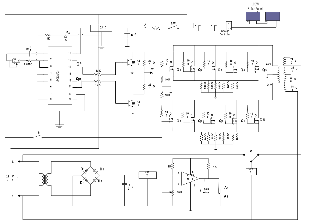 | Figure 1. Circuit Diagram of a Solar Powered Square Wave Inverter |
a. Square Wave InverterSquare wave inverters provide the simplest form of output waveform that run simple appliances without problems. Square wave voltage is easily generated using a two transistor as stable oscillator. With the help of a transformer, the generated square wave voltage can be transformed into a value of 230V AC or higher and the peak voltage is the same as the root mean square voltage [6]. The output waveform of this type of inverter is shown in Figure 2.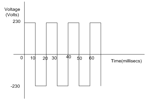 | Figure 2. Output waveform of a square wave inverter |
b. Modified Square Wave InvertersModified square wave inverters are designed to simulate a sine wave since the generation of sine wave is expensive. This waveform consists of a flat of positive voltage, dropping abruptly to zero for a short period, then dropping again to a flat of negative voltage. It then goes back to zero again and returns to positive. This short pause at zero volts gives more power to 50Hz fundamental frequency of AC than the simple square wave. The modified square wave can be generated by using integrated circuits like SG3525, T1494, and SG3524. The output of a modified square wave inverter contains lesser harmonic distortions as compared to the square wave inverter. A modified square wave inverter supplies a constant root mean square voltage with the use of a feedback circuit of the integrated circuit used as the oscillator [6]. The waveform of this type of inverter is shown in Figure 3.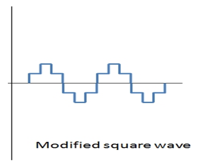 | Figure 3. Modified Square Wave Inverter |
c. Pure Sine Wave InverterPure sine wave inverter produces a sine wave output with a very little harmonic distortion. Sine wave inverters are more complex and cost higher than a modified square wave type of the same size. Sine wave can be generated by using a Wien bridge oscillator, Bubba oscillator and phase shift oscillator. Pure sine wave inverters also implement the PWM technology, but a different and more advanced than that of a modified sine wave inverter. The method used is called Sine Pulse Width Modulation (SPWM). The SPWM is generated by feeding a reference and carrier signals to a comparator which creates output signals based on the difference between the two input signals. The reference signal is sinusoidal and at the frequency of the desired output signal, while the carrier signal is often either a saw-tooth or triangular wave at a frequency significantly greater than the reference [6]. The output waveform of this type of inverter is shown in Figure 4. | Figure 4. Output waveform of a pure sine wave inverter |
d. Load Regulation and Backup DurationWhen there is additional load on the inverter, there is usually a reduction in the output voltage of the inverter but due to feedback control present in SG3524 IC, the voltage is automatic regulated from the output of the transformer and keep the output voltage constant irrespective of load applied. Therefore, the output of the inverter made from SG3524 IC remain constant with variation in load in as much as the battery is still supplying the required voltage.  | (1) |
In this paper, since the battery voltage is 24 and ampere hour rating is 150AHTherefore, battery power rating = 24 x 150 = 3,600VAHHowever,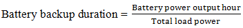 | (2) |
For a total load of 200W,Battery backup duration =  = 18hrs.e. Power Switching StagePower switching MOSFETs are employed in the power driver stage since they have high switching speed. The input to the power MOSFETs is fed from the buffer amplifier through a parallel path. IR3205 MOSFETs were selected for the design of this stage and they give power dissipation of 250W. To determine the number of MOSFETs required and the current they can withstand, power voltage relation was used
 | (3) |
where: P is the power rating of inverterI is the maximum current that can flow through inverterV is the battery voltageIf P is 3500W and V is 24, the maximum current that will flow through the MOSFETs is calculated as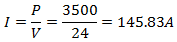 since each of the MOSFETs has a current rating of 35A, the numbers required is then calculated using
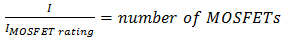 | (4) |
where  is the current rating of each MOSFET
 | (5) |
From the calculation, five MOSFETs is required for the power switching stage but in order to prevent the MOSFETs from burning and to boost the performance of this stage, a total of ten of power MOSFETs (IR3205) five each for the two segments are used for the project in order to meet the project specification. In this stage, the power MOSFETs alternately switches the 24V battery supply across the windings of a center-tapped transformer thereby producing 220V A.C at a frequency of 50Hz as shown in Figure 2. It should be noted that 10kΩ resistors are used in the circuit to create high input impedance when no load is applied to the output socket. This is to prevent the MOSFETs from burning while resistors  protect the MOSFETs from inrush current and also allow all MOSFETs to switch ON and OFF at the same time. As shown in Figure 5, MOSFETs
  and
and  switch alternately at regular interval of time. At the first half of the cycle, MOSFETs
  switches ON while MOSFETs
  is OFF, therefore, the D.C source voltage is impressed across the primary side of the transformer. At the second half of the cycle, MOSFETs
  switches ON while MOSFETs
 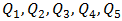 is OFF and also the DC source voltage is applied to the primary side of the transformer. The continuous switching of the MOSFETs alternatively generate an A.C voltage across the primary winding of the transformer, which induces a 220V A.C at 50Hz at the secondary side of the transformer. The secondary voltage is therefore connected to the load through an outlet socket.
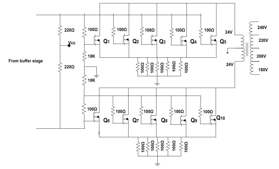 | Figure 5. Power Switching Circuit |
3. Maximal Ratio Combiner
Maximal Ratio Combiner (MRC) is a combining technique in which signals from different diversity branches are co-phased and weighted before summing. The weight is chosen as proportional to the respective signals level for maximizing the combined Carrier-to-Noise Ratio (CNR). MRC is the optimal combining scheme (regardless of fading statistics) but at the expense of complexity due to knowledge of all channel fading parameters [11]. It is a combining technique that achieves the best performance improvement compared to other methods that is very useful in combating channel fading. It is a commonly used technique to improve performance of the system in a noise communication channel where the Additive White Gaussian Noise (AWGN) and fading are independent amongst the diversity branches. Since knowledge of channel fading amplitudes is needed for MRC, this technique is used in conjunction with unequal energy signals, such as M-ary Quadrature Amplitude Modulation (M-QAM) or any other amplitude and phase modulations. Fig 6 shows the block diagram of MRC, it consists of three receiving antennas which receive the corrupted signal through the space. The signal passes through the separate channel estimator and matched filter and combine before detection. MRC having L number of branches, the output Signal to Noise Ratio (SNR)  is given by [12] as
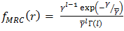 | (6) |
where:  is the instantaneous SNR which is the output of FA, that is, optimized paths
 is the average SNR
 is the Gamma function
 is the diversity branch
 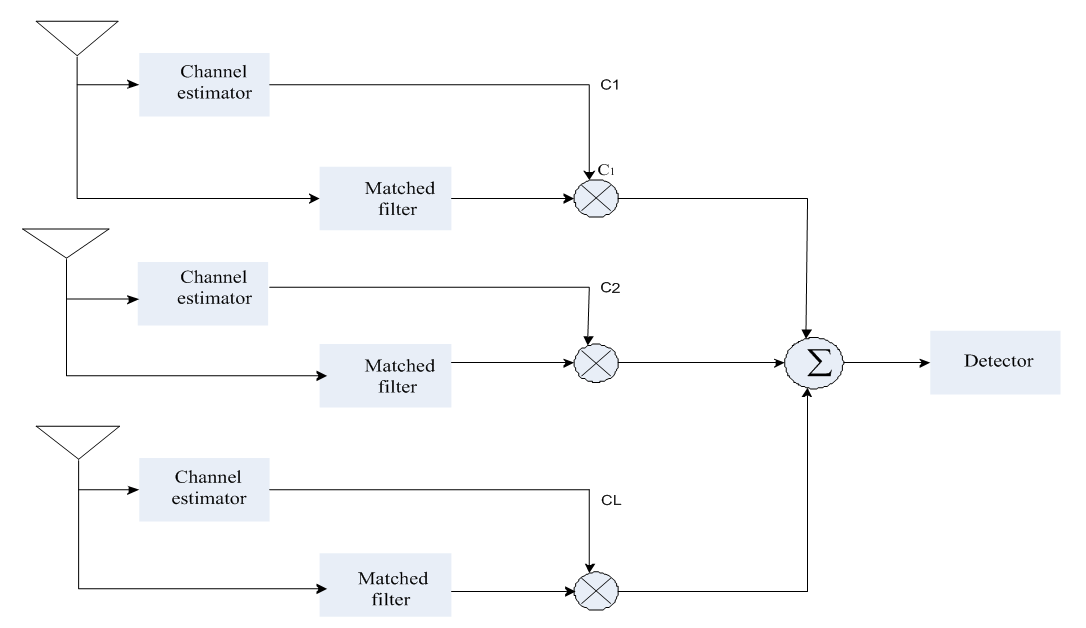 | Figure 6. Block diagram of Maximal Ratio Combiner |
The probability density function (PDF) of the MRC output is given by [13,14] as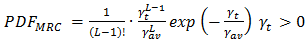 | (7) |
where:  is the average SNR at each diversity element,
 is the SNR ratio at the output of the MRC and
  is the number of path.
4. Development of an Improved SMS Module and Incorporation with Inverter
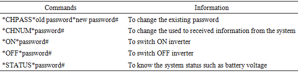
Short Message Service (SMS) circuit comprises of MODEM (GSM phone) and microcontroller. The power for this circuit is being drawn from the 12V battery which then regulated by constant voltage regulator (7805) to a 5V because of MODEM and microcontroller that required 5V constant voltage supply at the input. MODEM has transmitting port (Tx) and receiving port (Rx). Rx port receive message from the owner of inverter by a recognize password. This message is then transmitted to the microcontroller through port Tx. ATMEGA328P (microcontroller) also has Tx and Rx port which stand for transmitting and receiving port respectively. Rx receives message from MODEM, this message is then decoded and interpreted by ATMEGA3228P. pin 14 (output pin) of the chip in Fig 7 is then connected to the base of transistor Q1, collector of this transistor is also connected to the coil of relays. Signal in the base of transistor Q1 switch on Q1 and thereby moves relay from normally close (NC) to normally open (NO). Common (C) of relay is connected in series with the inverter switch which then control the inverter by switching ON and OFF. The owner of inverter can also receive feedback from the inverter through Tx port of ATMEGA328P and Rx of the MODEM. This message is then transmitted to the mobile phone of the owner of inverter through Tx port of the MODEM. In order to improve the performance of this circuit, MRC is used to combined the multiple copies of the signal and output of this combiner is then serves as input to the MODEM. The MODEM operate at frequency of 1800MHz. The coil of a 9V relay is connected to the output of MODEM and the relay is in series with the inverter switch. The MODEM has an MTN sim which allowed anybody to communicate with the inverter as long as the number of that sim is known and provided there is network. MODEM received message from user and the output of MODEM move the relay to normally closed or normally open depending on the information whether to switch off the inverter or switch on the inverter. This later control the switch of inverter that is connected in series with the relay. The commands used and their function are shown in Table 1, while the circuit diagram of SMS is shown in Figure 7.Table 1. Commands and Information
 |
| |
|
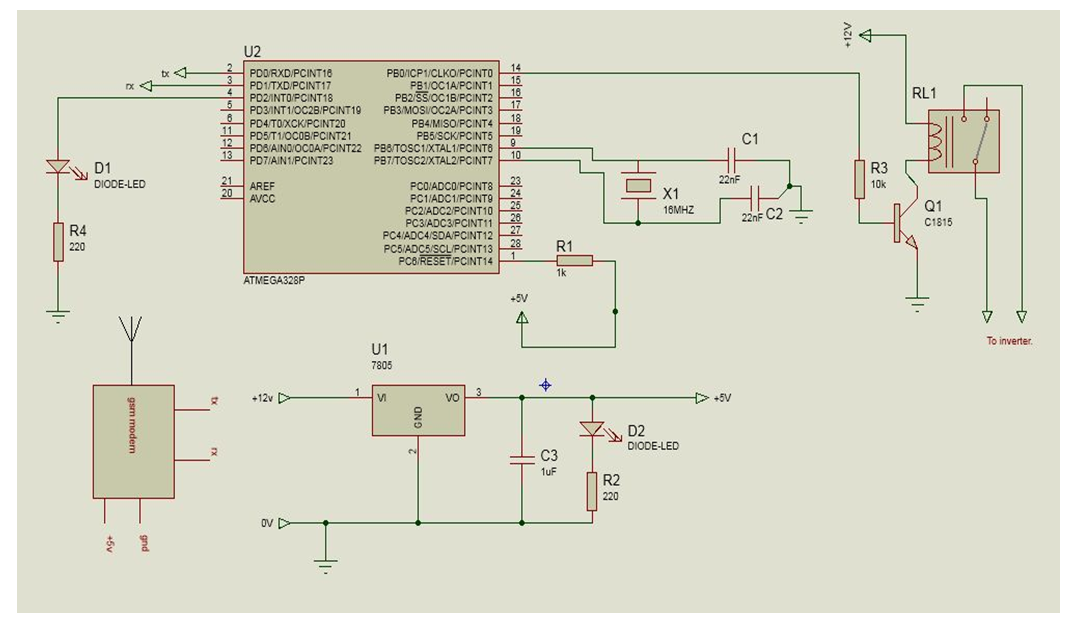 | Figure 7. SMS Control Circuit |
5. Results and Discussion
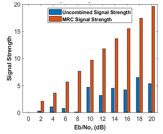
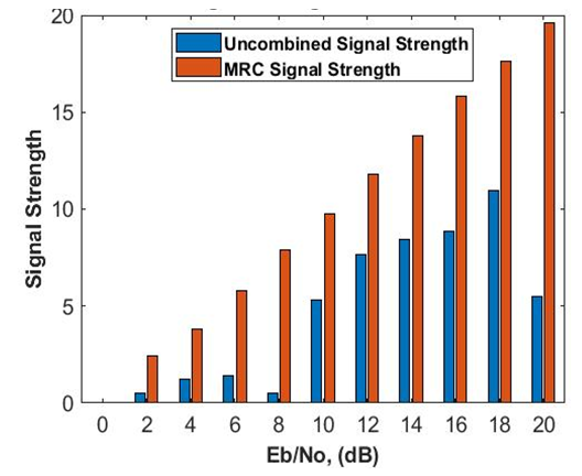
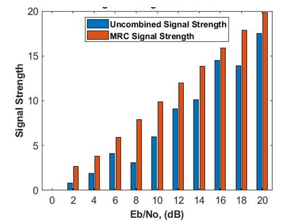
Signal Strength (SS) is used as a performance metric to measure the performance of the enhanced system. The value of signal strength obtained for conventional and enhanced SMS are presented in Figs 8 to 11. Fig. 8 shows the signal strength versus SNR for conventional and the enhanced SMS at 4QAM signalling scheme. The SS values obtained for the enhanced SMS are 1.5880, 3.3394, 5.5056 at SNRs of 2, 4, 6 dB, respectively, as against the conventional SMS with SS values of 0.0048, 0.2162, 0.1052 at SNRs of 2, 4, 6 dB respectively. Fig 9 show the SS versus SNR for conventional and enhanced SMS at 8QAM signalling scheme. At SNR of 2, 4, 6 dB, the SS values obtained for enhanced SMS are 1.6407, 3.6515 and 5.6540 as against the conventional SMS of 0.3050, 1.0873 and 0.8030, respectively. Similarly, Fig 10 depicts the SS versus SNR for conventional and enhanced SMS at 16QAM signalling scheme. It can be deduced that at SNR of 2, 4 and 6 dB, SS values obtained for enhanced SMS are 1.8626, 3.7914 and 5.8120, respectively, as against 0.5039, 1.2077 and 1.4110 obtained for conventional SMS. Also, in Fig 11, at 32QAM signalling scheme, SS values obtained for enhanced SMS at SNR of 2, 4, 6 dB are 1.9860, 3.8334 and 5.9335, respectively, while 0.8048, 1.8964 and 4.1410 are respectively obtained for conventional SMS.  | Figure 8. Signal Strenght versus SNR for Ehanced and Conventional SMS with 4QAM Signalling Scheme. |
 | Figure 9. Signal Strenght versus SNR for Enhanced and Conventional SMS with 8QAM Signalling Scheme. |
 | Figure 10. Signal Strenght versus SNR for Enhanced and Conventional SMS with 16QAM Signalling Scheme |
 | Figure 11. Signal Strenght versus SNR for Ehanced and Conventional SMS with 32QAM Signalling Scheme |
6. Conclusions
In this paper, an enhanced SMS controlled solar powered inverter has been proposed. The system has been simulated and evaluated using signal strength at different constellation and SNR. The results showed that the enhanced SMS performs relatively better than the conventional SMS due to higher SS values. The performance of the enhanced SMS is as a result of combining nature of the signals before applying GSM module. Therefore, the enhanced SMS has been showed to have a better performance by having a higher SS than the conventional SMS. The study showed the signal outage reduction and can be incorporate with inverter system for proper communication.
References
| [1] | Fernando O., Silvia O., Maria, P.V, Natascia, A. and Alessandro, L. ‘Technical and Economical Evaluation of Fast Charging Infrastructures for Electric Buses, AIP Conference Proceedings, Italy, PP 1-12. 2019. |
| [2] | Kivalov, S.K Zakhidov R.A (2001). Application of concentrating systems for the photovoltaic conversion of solar radiation. Applied solar energy, 37 (3), pp. 59-70. |
| [3] | Proakis, J. G. (2001), “Digital Communications”, Mc Graw-Hill companies, inc., International Edition: pp 87:98. |
| [4] | Heksi L., Maarten, A., Hans B., Budhi, G. and Johan, I. Sustainability of Renewable Off-Grid Technology for Rural Electrification: A Comparative Study Using the IAD Framework, American Journal of Electrical and Electronic Engineering 6 (3): 1-12. 2018. |
| [5] | Mikias, H. K. Design of Standalone PV System for a Typical Modern Average Home in Shewa Robit Town-Ethiopia. American Journal of Electrical and Electronic Engineering 6 (2): 1-12. 2018. |
| [6] | Olajuyin E. A. and Olubakinde E. Design of 2kVA Solar Inverter, Journal of Emerging Trends in Engineering and Applied Sciences 8(6): 257-262. 2017. |
| [7] | Sarah, F., Harald, H. and Raul, R. C. Sustainability of Rural Electrification Programs Based on Off-Grid Photovoltaic (PV) Systems in Chile, Journal of Energy, Sustainability and Society 4(3): 6:32. 2016. |
| [8] | Mohamed S, and Marvin K. S. Performance of Coherent Receiver with Hybrid SC/MRC Over Nakagami-m Fading Channel, IEEE Transactions on Vehicular Technology 48(4): 1155-1157. 1999. |
| [9] | Adeyemo, Z.K, and Ojedokun, I.A. EGC Receiver using Single Radio Frequency Chain and Single Matched Filter over Combined Rayleigh and Rician Fading Channels, ARPN Journal of Engineering and Applied Sciences, 9(7): 992-994. 2014. |
| [10] | Adeyemo Z.K. (2019). Development of a Hybridized Diversity Combiner over Nakagami Fading Channel, International Journal of Information Engineering and Electronic Business 3 (1): 45-53. |
| [11] | Ramanthan V. Performance Evaluation of Equal Gain Diversity Systems in Fading Channel, Master Thesis Submitted to the Faculty of the Virgiria Polytechnic, Institute and State University pp 1-4. 2003. |
| [12] | Hima P.V and Seema P. Performance Analysis of Hybrid MRC/EGC Diversity Combining Technique over AWGN channel, IOSR Journal of Electronics and Communication Engineering 42(2): 25-26. 2016. |
| [13] | Proakis, J. G. “Digital Communications”, Mc Graw-Hill companies, inc., International Edition: pp 87:98. 2001. |
| [14] | Stuber, G.L. “Principles of Mobile Communications, “Second Edition, Kluwer Academic Publishers New York: 245-267. 2002. |
| [15] | Theraja A.K and Theraja B.L, “A Textbook of Electrical Technology”, 4th Edition, S. Chand Company, India. 2000. |
| [16] | Sarah, F. Sustainability of Off-Grid Photovoltaic Systems for Rural Electrification in Developing Countries: A Review, American Journal of Electrical and Electronic Engineering 4 (3): 1-20. 2016. |

 Abstract
 Reference
 Full-Text PDF
 Full-text HTML