-
Paper Information
- Paper Submission
-
Journal Information
- About This Journal
- Editorial Board
- Current Issue
- Archive
- Author Guidelines
- Contact Us
Electrical and Electronic Engineering
p-ISSN: 2162-9455 e-ISSN: 2162-8459
2019; 9(2): 41-44
doi:10.5923/j.eee.20190902.03

PIC32MZ Milliseconds and Microseconds Delay Routines
 Abstract
 Reference
 Full-Text PDF
 Full-text HTML
Abhishek N. Patel
Research and Development Department, Horiba Instruments Inc., 20 Knightsbridge Road, Piscataway, New Jersey, United States
Correspondence to: Abhishek N. Patel, Research and Development Department, Horiba Instruments Inc., 20 Knightsbridge Road, Piscataway, New Jersey, United States.
| Email: |  |
Copyright © 2019 The Author(s). Published by Scientific & Academic Publishing.
This work is licensed under the Creative Commons Attribution International License (CC BY).
http://creativecommons.org/licenses/by/4.0/

This paper demonstrates how to make millisecond and microsecond delay routines for PIC32MZ/PIC32 MCUs by utilizing internal clock speed of MCU. Delay routine used to suspend execution of a program for a particular time. Unfortunately, the microchip PICXC32 compiler does not give us a delay function/API to call from firmware application layer. This implementation requires PIC32MZ/PIC32 MCU based hardware and microchip MPLAB-X IDE, tool chain and Harmony framework.
Keywords: C, PIC32MZ, PIC32, Firmware, Embedded System, Delay, LED Blinker
Cite this paper: Abhishek N. Patel, PIC32MZ Milliseconds and Microseconds Delay Routines, Electrical and Electronic Engineering, Vol. 9 No. 2, 2019, pp. 41-44. doi: 10.5923/j.eee.20190902.03.
Article Outline
1. Introduction
- An embedded system interacting with physical world, which sometime does not fast as fast a computer instruction. In addition, it can be design based on state driven or interrupt driven or based on external source state, where it needs to hold and wait or stay in same state for some time before executing next instruction. There are multiple way to accomplish this, one of them via delay. The problem I encountered was that I want to read the temperature of a chamber and if current temperature is same as requested temperature then indicate it by setting an LED. Now I cannot take it continuously, as the temperature of a chamber will not change every millisecond/microsecond. Therefore, I insert a delay in acquiring the temperature of the chamber. Delay used to take periodic inputs from the real world so that the system is practical and it save up memory in the PIC32 microcontroller/small target based system.
2. How to Make Routines for Millisecond and Microsecond Delays
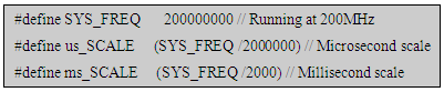
- The LED blinker program that is a good starting point with any 32-bits MCU like PIC32MZ as it utilizing clock speed. A sign of success, those things are working and clock speeds are right. Unfortunately, the microchip PICXC32 compiler does not give us a delay function/API to call. There is a built-in timer in every PIC32 called the Core Timer. It does not need to be set up and it is always running. It runs at half the system frequency, so if we are running at 200MHz then it will update at 100MHz. First, let us add define for how fast we have set the fuses to. This value will be useful for many calculations we will need to do later.
 Next is, how do we use the Core Timer? First, we need to calculate how long we need to wait. For an Example here, the core timer updates at 100MHz. Let us say we target to wait 500 microseconds. First, we needs to calculate number of clock tick requires for that.When running 200MHz, Core Timer frequency is 100MHz Core Timer increments every 2 SYS_CLK, Core Timer period = 10ns
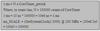 Let us put it to gather and make a microsecond delay function:
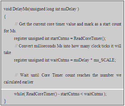 First, we calculate how many clock ticks we need to wait. Then we read current Core Timer counter and wait until it match to the number of wait count (i.e. waitCntms) value.
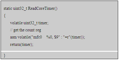 Similar to that, create a microsecond delay now.
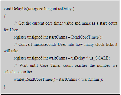 NOTE: This implementation could be off by few clock cycles. As the Core Timer is a 32-bit number, which means it can only count to 4 billion before it'll wrap back around to 0. So don't use these routines for hundreds of seconds. Now let us make that LED dance!
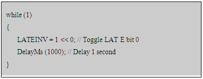 LATEINV is an easy way to toggle bits on Port E and requires no work on our part.
 3. Millisecond Delay Routine Real World Usages for Temperature Monitoring
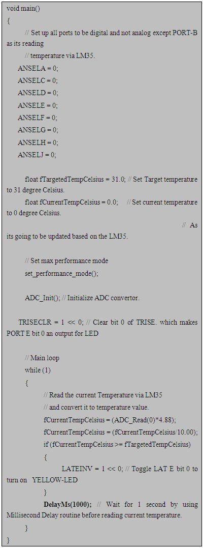
- This section describe application of millisecond delay routine for temperature monitoring. We have define target temperature at the start of program and turn on LED once current temperature equal to targeted temperature. For this comparison, we needs to read back a current temperature after every 1 second, as it is not going to change micro/milliseconds. We are waiting for 1 second using millisecond routine and then read back the temperature via LM35 sensor. LM35 is a temperature sensor, which can measure temperature in the rage of -55°C to 150°C. A three terminal device provides analog voltage proportional to the temperature. Higher temperature reports high output voltage and lower temperature reports low output voltage. The LED remain off till its reaches to the targeted temperature and once current temperature equal or greater than targeted temperature then it will turn on the LED.
3.1. Code for PIC32MZ and LM35 Temperature Sensor with LED
- This sample code design to read a current temperature via LM35 and compare it to targeted temperature. If it equal or greater than targeted temperature then turn on the YELLOW-LED to indicates it.
4. Millisecond Delay Routine Real World Usages for Writing to the External EEPROM via i2C Bus
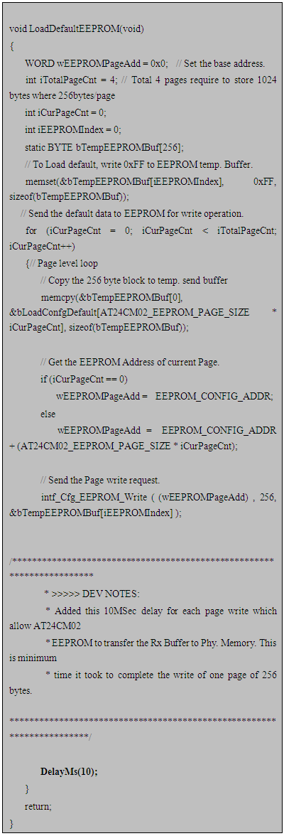
- This section describe application of millisecond delay routine to implement EEPROM write cycle time as per datasheet of AT24CM02 (Microchip 2MB EEPROM memory). When we try to write a data to EEPROM, it initially received into a buffer and getting transfer from received buffer to physical EEPROM memory during a write cycle time. Therefore, for write operation PIC32MZ microcontroller needs to wait in between sending multiple data packet to EEPROM. The AT24CM02 EEPROM requires 10Miliseconds between two-write operation as a write cycle time. This implemented successfully by calling a millisecond routine between two-write operations (for more detail refer AT24CM02 datasheet chapter-5.5).
4.1. Code for PIC32MZ and AT24CM02 EEPROM
- This sample code implemented successfully on PIC32MZ2048EFM with AT24CM02 EEPROM, which restores first four pages of EEPROM to default “0xFF” value and wait for 10 Milliseconds by calling Millisecond delay routine(i.e. DelayMs(10)) between each page write (As per AT24CM02 datasheet recommended write cycle time).
5. Conclusions
- These costume Delay routines can be useful for any PIC32 embedded system based project. There could be a numerous condition in real world applications where we need this microseconds/milliseconds delay routines to hold application into current state and wait for other events to complete an execution. These delay routines implemented successfully using PIC32MZ MCU hardware and MPLAB software stack that includes MPLAB X IDE, Tool chain and Harmony framework. The above example of temperature monitoring and EEPROM write cycle time demonstrated usages of millisecond delay routine.