-
Paper Information
- Next Paper
- Paper Submission
-
Journal Information
- About This Journal
- Editorial Board
- Current Issue
- Archive
- Author Guidelines
- Contact Us
Electrical and Electronic Engineering
p-ISSN: 2162-9455 e-ISSN: 2162-8459
2019; 9(2): 27-34
doi:10.5923/j.eee.20190902.01

STF-pq Approach for Harmonics Mitigation in Stand-Alone PV System
 Abstract
 Reference
 Full-Text PDF
 Full-text HTML
Serge Raoul Dzondé Naoussi1, Daniel Soeun Haalé1, Léandre Nneme Nneme2
1Laboratory of Technology and Applied Science, IUT, University of Douala, Douala, Cameroon
2Laboratory of Control and Computing Engineering, ENSET, University of Douala, Douala, Cameroon
Correspondence to: Serge Raoul Dzondé Naoussi, Laboratory of Technology and Applied Science, IUT, University of Douala, Douala, Cameroon.
| Email: |  |
Copyright © 2019 The Author(s). Published by Scientific & Academic Publishing.
This work is licensed under the Creative Commons Attribution International License (CC BY).
http://creativecommons.org/licenses/by/4.0/

In this paper, we present harmonics compensation technique, by means of Instantaneous Powers (pq) theory based on Self-Turning Filter (STF) in a stand-alone Photovoltaic System (PVS). Active Power Filters (APFs) used for this purpose are also dedicated to reactive power compensation. The STF is used to obtain DC components from instantaneous voltages or currents to compute reference currents extraction. These currents are injected in opposite phases with a Source voltage Inverter (VSI) for harmonics mitigation. Various simulation results obtaining in Matlab-Simulink environment, under ideal conditions, irradiance and/or temperature step change, sudden changes on non-linear loads, are introduced to show the effectiveness of this technique, by means of total harmonic distortions (THD) measurement.
Keywords: Stand-alone PV systems, Harmonics mitigation, Self-Tuning Filter, pq-theory
Cite this paper: Serge Raoul Dzondé Naoussi, Daniel Soeun Haalé, Léandre Nneme Nneme, STF-pq Approach for Harmonics Mitigation in Stand-Alone PV System, Electrical and Electronic Engineering, Vol. 9 No. 2, 2019, pp. 27-34. doi: 10.5923/j.eee.20190902.01.
Article Outline
1. Introduction
- A Stand-Alone Power System (SAPS), also known as remote area power supply, is an off-the-grid electricity system for locations that are not connected to a power distribution system, such as sewage treatment plant, household application, remote industries in some developing countries, etc. Typical SAPS includes one or more methods of electricity generation, energy storage, and regulation [1]. Among them, there is the Photovoltaic System (PVS) using solar panels. The basic model of a direct coupled PVS consists of a solar panel connected directly to DC loads. As there are no battery banks in this setup, energy is not stored and hence it is capable of powering common appliances like fans, pumps, etc. only during the day. In SAPS, the electrical energy produced by the photovoltaic panels cannot always be used directly. As the demand from the load is not always equal to the solar panel capacity, battery banks are generally used, but other solutions do exist for example fuel cells [2-3]. Power drawn directly from the battery is used especially for lighting as well as for DC appliances. An inverter is used to generate AC low voltage, which more typical appliances can be used with. So many industrial and residential loads are nonlinear, it stands that, the relationship between voltage and current is nonlinear. In order to reduce distortions created by these type of loads, the Active Power Filter (APF) is nowadays one of the most powerful solutions. It is therefore used in a distribution power system to avoid serious inherent problems such as transformer overheating, machine vibration, motor failures, higher line losses, etc. The switching actions of power converters result to distortion on the input currents, which contain a fundamental and some higher order harmonics. Injection of compensation currents in the electrical power supply by means of an APF, allows reactive power compensation as well as sinusoidal current shape recovery, to meet Total Harmonics Distortion (THD) limits set by IEEE Standard 519-1992. This standard has now been revised as IEEE Standard 519-2014 [4]. Nevertheless, the THD limit of 5% for current is still valid in the latest IEEE standard.Harmonics compensation consists first of detecting the distorting load currents, and their injection to the power grid by means of APF converter switching. Although APF performances depend on the designing methods of both functions, the filtering quality is essentially affected by the current references generation. Most of the contributions for harmonics extraction were in time domain. For example, the Synchronous Reference Frame (SRF) theory is based on the filtering of DC current components by a low-pass filter in synchronously rotating frame [5]. At the beginning of the 1980s, Instantaneous Reactive Power Theory (pq) emerged and is still now one the most powerful techniques for distortions identification in power systems. The objective of the pq was to find an effective control strategy to compensate harmonics in power systems by means of an APF [6]. Many recent works are trying to improve APF control by developing new laws. In this way, Artificial Neural Networks (ANNs) based techniques have been successfully applied in active filtering [7], with interesting adaptive properties. Another alternative is by using an adaptive notch filter (ANF) [8]. In [9], ANF is applied together with the pq theory approach to generate the required reference current for APF. The ANF is used to process the non-sinusoidal source voltage and distorted load current so that the fundamental voltage and current components can be extracted to. compute the required fundamental average power. The fundamental average power is the main parameter involved in reference current generation. However, the performance of ANF strictly depends on its damping ratio and adaptation gain, which requires a fine tuning process to work effectively. Besides, the work is limited to simulation studies only.A better alternative is by incorporating a Self-Tuning Filter (STF) [10, 11]. STF-pq theory algorithm is much more preferable as it does not require additional Phase Locked-Loop (PLL) elements for synchronization purposes. Most importantly, as reported in [12] the STF-pq theory algorithm works effectively under both steady-state and dynamic-state conditions for active filtering in power grid system. Therefore, this paper presents STF-pq theory algorithm which suits the operation of producing reference current to govern the operation of the designated APF, in the context of SAPS. Three aspects are identified for characterizing the overall energy system: the PV generation with MPPT based on P&O algorithm [13], the reference currents extraction, the source current compensation. The design concept and effectiveness of the proposed algorithm are verified using MATLAB-Simulink. For performance comparison, the system is tested under highly nonlinear steady-state and dynamic-state conditions.The rest of the paper is organized as follows: In Section 2, the stand-alone PV is presented in its complete structure including energy storage with battery, the DC-DC and DC-AC converters. Section 3 presents the STF-pq approach for harmonics extraction in APF control scheme. The simulation results are presented, and critically discussed in Sections 4, by showing the effectiveness of the chosen algorithm even in Stand-alone PVS. The paper ends with a brief conclusion in Section 5 by summarizing significant contributions of this work.
2. Modeling of a Stand-alone PVS
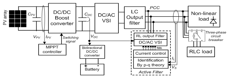
- Fig. 1 presents the following main parts of a direct-coupled stand-alone PVS: - The PV panel - The boost DC-DC converter- A VSI for DC-AC conversion and its output filter- The loads (non-linear and/or linear)
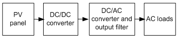 | Figure 1. Block diagram of a stand-alone PVS |
2.1. PV Panel Modeling
- An ideal solar cell can, theoretically, be modeled as a source current in anti-parallel with a diode. The equivalent circuit of a single diode PV cell [14-16] is depicted in Fig. 2. In an ideal PV cell, series resistance (
 , no series loss) and shunt resistance (
 = infinite, no leakage to ground). The PV cell terminal current
  is equal to the light produced current
  , minus the diode current
  and the shunt leakage current (or ground-shunt current,
  ). The series resistance
  represents the internal resistance to the current flow. The shunt resistance
  is inversely related to leakage current to the ground.
 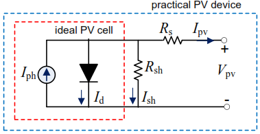 | Figure 2. The electrical equivalent circuit model of a PV cell |
 | (1) |
 is the photo-current generated by the solar irradiation to the p-n junction cell;
  is the diode saturation current;
  and
and  are series and shunt resistances of the PV cell, respectively. For PV array consisting of Ns series and Np parallel connected PV modules, (1) becomes
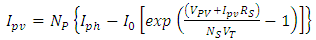 | (2) |
 is the thermal voltage of the array with Ns cells connected in series,
 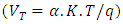 ; q is the Coulomb’s constant (1.602×10⁻¹⁹ C); K is the Boltzmann’s constant (1.381×10⁻²³ J/K); T is the cell temperature in ºK;
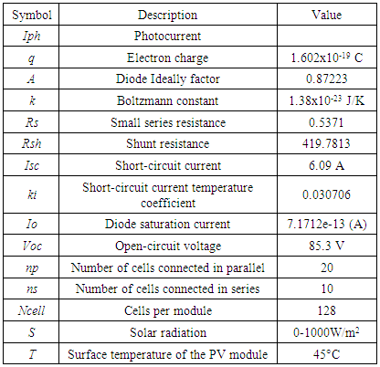
  is the p-n junction ideality factor of the diode (1 for an ideal diode). Cells connected in parallel increase the PV current whereas cells connected in series provide greater PV output voltage. All the other parameters can be obtained from the solar panel specifications which are shown in Table 1.
|
2.2. DC-DC Converter
- The DC-DC converter is an electronic circuit that provides a lossless transfer of energy between different circuits at different DC voltage levels [19]. A DC-DC Boost converter is proposed and favored in the stand-alone PV framework since it can venture up little DC voltage delivered by the PV panel to a higher value suitable for the DC-AC Source voltage Inverter (VSI) [20].
2.3. DC-AC Source Voltage Inverter
- In the PVS, DC-AC VSI is used to change the DC voltage from the DC-DC Boost Converter output into AC voltage required for AC loads. Pulse Width Modulation (PWM) is generally used to control the VSI so as to produce appropriate gating signals for switches [20]. The sinusoidal voltage is then obtained through a low-pass filter available at the VSI output for harmonics reduction. By using a LC-type low-pass filter, the channel inductance L is computed such that the voltage drop is under 3% of the inverter voltage
 [18]. This leads to the relation as follows:
 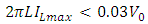 | (3) |
 is the maximum RMS (Root Mean Square) value of the load current, f is the voltage frequency (50Hz) and
  is the RMS estimation of the VSI voltage. The channel capacitance C is also obtained as
 | (4) |
 is the cut off frequency.
3. Self-Tuning Filter-based Instantaneous Power Theory
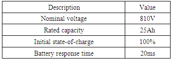
- Fig. 3 presents the structure of the whole system powered by the PV panel highlighting some details on control blocks. The PVS source is powering a non-linear load through DC-DC and DC-AC converters. Since the DC-link voltage VDC is guaranteed by a battery considering solar irradiance and temperature variation during the whole day, the boost converter is controlled via MPPT controller. The perturbation and observation method is preferred in this system due to its simplicity and robustness to the variations of model parameters. More details about this MPPT method is well described in [13] and will not be focused in this paper.
 | Figure 3. Active filtering structure in stand-alone PVS |
3.1. Reference Currents Identification by STF-pq Method
- The pq approach used for reference currents identification is described in Fig. 4.
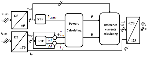 | Figure 4. pq identification method scheme |
 | (5) |
 to yield
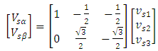 | (6) |
 | (7) |
 and
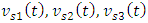
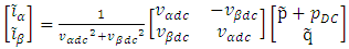
and  represent fundamental (dc) and distorted (ac) components of the source voltage in αβ-domain respectively. In order to deal with this condition, a Self-Tuning Filter (STF) is commonly applied for source voltage DC components extraction. These components are used to ensure in-phase operation of the APF with the designated power system. On the other hand, under the influence of nonlinear loads, the load current in αβ-domain can also be decomposed into DC and AC components. For reference currents generation, both
  and
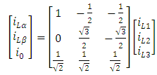
and  components are required. The DC components are first extracted by using a second STF followed by the removal of the extracted DcC components from the actual load current in αβ-frame as presented in Fig. 4.As shown for voltage and current respectively, the STF principle is based on the extraction of the DC (fundamental) component from a signal X [21]. The relations linking components
  at the output of the STF with those from the input,
  are expressed as follows:
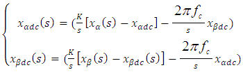 | (8) |
 is the input current or voltage from the α-β axis
  the fundamental component of
  K is a constant gain parameter and fc is the cut-off frequency. fc is equal to 50 Hz.In order to achieve the best filtering performance of STF in extracting DC components of source voltage, K is commonly set at 100 [12]. When STF is applied on currents, K it is between 20 and 80. Fig. 5 gives the description of the STF blocks according to equation (8).
 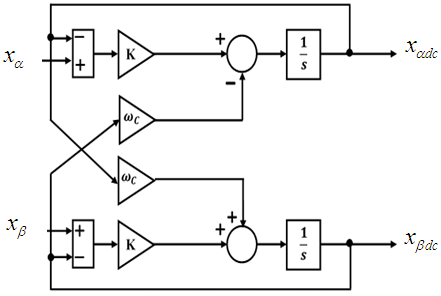 | Figure 5. STF diagram block |
 and the harmonics currents
  , it is therefore possible to compute the alternative component of p and q. Hence it is obtained as
 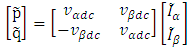 | (9) |
 as follows:
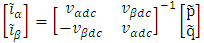 | (10) |
 | (11) |
 is the additional power to achieve the capacitor voltage
  regulation, at the DC side of the inverter. By the inverse Concordia transform, the reference compensating currents in the 1-2-3 coordinates are then obtained as
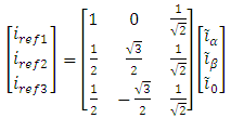 | (12) |
 and the current controller forces the subsequent PWM switching pulses in controlling mitigation operation of APF.
3.2. Current Control
- At the APF output another passive filter is utilized to reduced high frequencies harmonics due to the switching operations of the inverter. The
 designing is realized with the constraint for a given switching frequency. The slope of the current
  is smaller than that of a triangular carrier, setting the switching frequency. The slope of the triangular carrier
  is defined as
 | (13) |
 the switching frequency of the crossover switches. The maximum slope
  , in the case of a crossover at midpoint, is given as
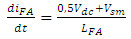 | (14) |
 estimated as follows :
 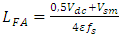 | (15) |
4. Results and Discussions
- Models and all of the simulations are carried out in the Matlab/Simulink environment. The objective is to validate and to show the effectiveness of active compensation of harmonics-based STF.
4.1. PV Generation
- An analysis of a PV panel can be done by its I-V and P-V characteristics. In our work, we use SunPower SPR-415E-WHT-D array type made up of 10 series modules and 20 parallel strings. Fig. 6 shows its characteristics for two values of temperature, i.e. 25°C and 45°C where the Maximum Power point is highlighted with a circle.
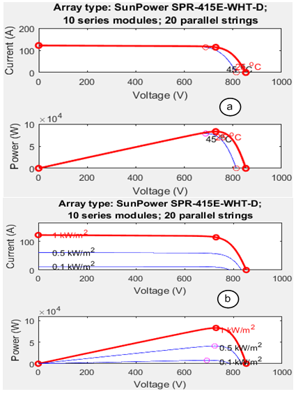 | Figure 6. I-V and P-V characteristics of the PV panel (a) 1000W/m2 and specified temperatures (b) 25°C and specified irradiances |
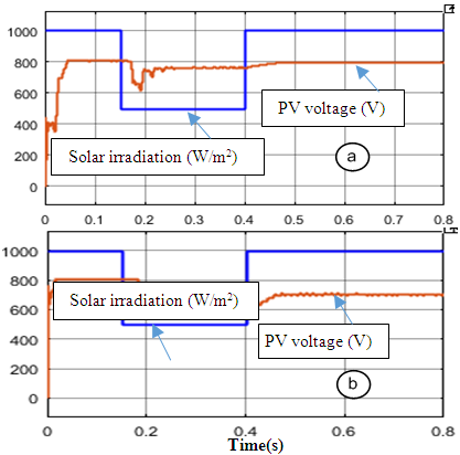 | Figure 7. Solar irradiation (W/m2 and PV output voltage (V)) a) without battery b) with battery |
4.2. DC-DC Block
- Simulation results are shown in Fig.8, where after a particular change of load parameters, the voltage sets a time delay of 0.06 s to reach the maximum. But in the presence of battery, it quickly changes with a settling time of about 0.04s. It is obvious that the converter has increased the voltage value, i.e. from an input of 750V to an output of 1100V at 0.6s.
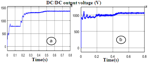 | Figure 8. Output voltage of the DC/DC bloc (V) a) without battery, b) with battery |
4.3. Active Filtering Base on STF-pq Method
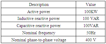
- Simulation analysis are performed under three conditions which involve - an ideal case : constant solar irradiance (1000W/m2) and constant temperature (45°C)- a sudden drop of solar irradiance at 500W/ m2 from 0.15s to 0.4s- a load change when a Three-phase RLC load is connected in parallel between 0.3s and 0.6sa. Results on ideal conditions In ideal conditions, the PV panel generates a DC voltage of 810V, as presented in Fig. 9.
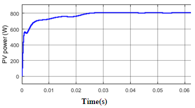 | Figure 9. Output voltage of the PV panel in ideal conditions |
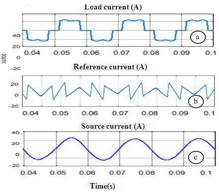 | Figure 10. Results obtained in ideal conditions with 1000W/m2 irradiance and 45° of temperature - a) the load current (source current before compensation) b) the reference current (harmonics current) c) the source current after compensation |
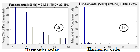 | Figure 11. Spectral decomposition of source current a) before compensation (a) after compensation |
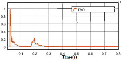 | Figure 12. THD curve for a drop of irradiance from 1000 W/m2 to 500W/m2 between 0.15s and 0.4s |
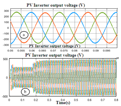 | Figure 13. Inverter output voltage according to solar irradiation a) before the change (1000W/m2) b) global waveform showing changes at 0.15s and 0.4s |
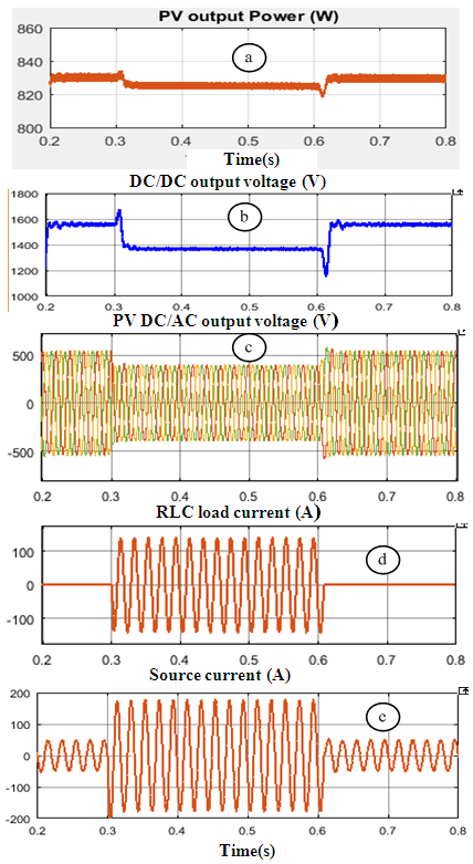 | Figure 14. Results obtained with a load changes at 0.3s and 0.6 a) PV output power b) Output voltage of the DC/DC/bloc c) Inverter output voltage (V) d) Current of the RLC load (load n°2) e) Source current after compensation |
|
|
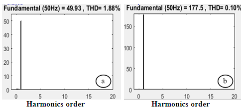 | Figure 15. Spectral decomposition of source current after compensation (a) before 0.3s and after 0.6s; b) between 0.3 and 0.6s) |
5. Conclusions
- This paper has successfully demonstrated a reference currents generation algorithm based on STF-pq theory for a three-phase VSI inverter-based APF, in the context of a stand-alone PVS. Three main scenarios were tested including ideal conditions, a step change of solar irradiation, and a change of load by connecting a new load of RLC type for a period of time. Comprehensive analysis was done both in the presence of a battery and without a battery, in order to evaluate the performance of the proposed combination of MPPT-STF-pq algorithms. Simulation results reveals that utilization of the proposed algorithm improves the mitigation performance of APF during steady-state conditions by achieving low THD values. From the results obtained, it has been proved that harmonics content of the PVS source current can be reduced at less than 1.88%, i.e. a THD under the IEEE limits of 5%. Moreover, a significant improvement can be observed during dynamic-state conditions where the proposed algorithm performs successfully with fast response times.