Electrical and Electronic Engineering

p-ISSN: 2162-9455    e-ISSN: 2162-8459

2019;  9(1): 9-16

doi:10.5923/j.eee.20190901.02


A Comprehensive Overview on the Development of Compensation Topologies for Capacitive Power Transfer System

Md. Nazrul Islam Siddique, Saad Mohammad Abdullah, Quazi Nafees Ul Islam

Department of Electrical and Electronic Engineering, Islamic University of Technology (IUT), Board Bazar, Gazipur, Dhaka, Bangladesh

Correspondence to: Md. Nazrul Islam Siddique, Department of Electrical and Electronic Engineering, Islamic University of Technology (IUT), Board Bazar, Gazipur, Dhaka, Bangladesh.

Email:

Copyright © 2019 The Author(s). Published by Scientific & Academic Publishing.

This work is licensed under the Creative Commons Attribution International License (CC BY).
http://creativecommons.org/licenses/by/4.0/

Abstract

Wireless power transfer (WPT) is becoming an attractive concept as an effective and convenient method of delivering power without direct metal-to-metal contact. Among WPT technologies; capacitive power transfer (CPT) system encounters less power losses compared to inductive power transfer (IPT) system around metal objects. This advantage makes CPT technology a prospective alternative to other prevailing technologies for high power and high efficiency wireless power transfer. To achieve considerable transfer distance, increased efficiency and high-power transfer level; proper designing of the compensation circuit is of utmost importance. In this paper, a comprehensive review of the body of research on different compensation circuit topologies including the advantages as well as disadvantages of each compensation topology are presented in order to summarize the current advancements in this field.

Keywords: Capacitive power transfer (CPT), Compensation topology, Efficiency, Fundamental harmonic approximation (FHA), Wireless power transfer (WPT)

Cite this paper: Md. Nazrul Islam Siddique, Saad Mohammad Abdullah, Quazi Nafees Ul Islam, A Comprehensive Overview on the Development of Compensation Topologies for Capacitive Power Transfer System, Electrical and Electronic Engineering, Vol. 9 No. 1, 2019, pp. 9-16. doi: 10.5923/j.eee.20190901.02.

1. Introduction

Wireless power transfer (WPT) is emerging as a means for various applications due to its inherent advantages over conventional means of power transfer ranging from low power biomedical implants [1] to electric vehicle (EV) charger [2]. Wireless power transfer involves the coupling of two or more coils at resonance frequency to transfer maximum power [3]. To transfer power without physical contact, inductive power transfer (IPT) and capacitive power transfer (CPT) are two techniques which have been employed effectively [4]. Figure. 1 shows the general schematic of wireless power transfer system.
Figure 1. Wireless power transfer block diagram
Here, loosely coupled coil pair are for inductive power transfer, coupled plates are for capacitive power transfer or a combination of coupled coil and plate are for the hybrid power system. DC from a battery or low frequency AC from a grid is provided to power the primary side. If the utility is AC, a power factor correction rectifier is used, followed by an inverter. If the utility is DC, a high-frequency converter is used and a primary compensation circuit aids to keep the primary input voltage and current in phase which minimizes the reactive power component and thus the size of the high-frequency power coupling (through loosely coupled coil pairs) or by electric coupling (through parallel plates) or by both. The secondary compensation circuit improves the power transfer capability of the system and voltage received is rectified and used to charge the batteries. CPT system utilizes the electric field [5-6] in-stead of magnetic field, which can encounter the metal barriers without generating considerable power losses [7] and can be employed where IPT system [8-9] is not convenient. Most of the present CPT systems concentrate on short-distance and low power applications such as integrated circuits (IC) [10], biomedical devices [11-12], LED lighting [13], USB and mobile charging [14-16] and the transmission distance is within several millimetres. When the transmission distance increases to the several hundreds of millimetres, the coupling capacitance deteriorates. Therefore, compensation topologies must be studied to increase both the system transfer distance and power level [17] to use CPT systems in electric vehicle charging applications. Based on the recent developments, this paper will review all the latest progresses in the compensation topologies of CPT technology, especially for the long-distance and high-power applications. The theoretical analysis and detailed implementations of compensation topologies will be presented and also the advantages and disadvantages of these topologies will be discussed thoroughly.

2. System Model

The structure and dimensions of CPT system are shown in Figure. 2. Plates P1 and P2 are placed at the primary side as the transmitter while plates P3 as well as P4 are placed at the secondary side as the receiver [10]. All the metal plates are considered to be identical with a side length of l1 to simplify the calculation of the circuit. The distance between the plates on the primary side is defined as ls1 and the distance between the plates on the secondary side is defined as ls2.
Figure 2. Structure and dimensions of the capacitive coupler [28]
The gap between the primary and secondary side is defined as d. Figure. 2. shows that there are capacitive couplings between every two plates, which results in six capacitors as depicted in Figure. 3. The simplified resonant circuit is shown in Figure. 4.
Figure 3. Six-capacitance model [28]
Figure 4. Simplified resonant circuit model
where,
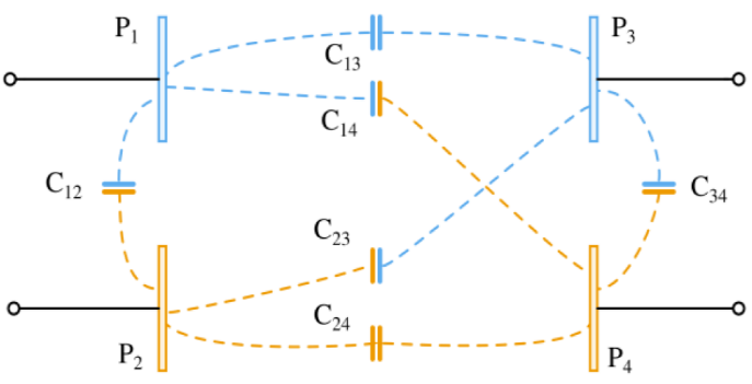
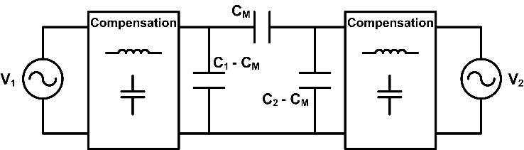
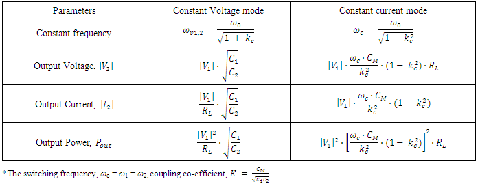
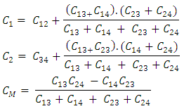
Here, C1 = self-capacitance at primary side
C2 = Self- capacitance at secondary side
CM = Mutual capacitance

3. Compensation Topologies for CPT System

Different CPT systems can be characterized by their compensation circuit topologies which determine the system output power, efficiency and frequency properties for a specific input and output conditions. The recent compensation topologies can be classified as non-resonant and resonant topologies. Pulse width modulation (PWM) converter is actually used as a non-resonant circuit. Resonant topologies can be realized by a high-frequency power amplifier or a full-bridge inverter with auxiliary components. So, the compensation circuit topologies can be outlined in three categories: PWM converter-based topology, power amplifier-based topology and full bridge inverter-based topology which will be discussed further.

3.1. PWM Converter Based Topology

The PWM converter with a single active switch such as Buck-boost, Cuk, Sepic and Zeta converter can be used to realize a CPT system [18]. In Figure. 5 there are two coupling capacitance CM1 and CM2 as a capacitive coupler and they work as energy storage components. When switch S turns off, CM1 and CM2 are charged by the input source and the inductor L1. When S turns on, the capacitances are discharged and power is transferred to the load.
Figure 5. Circuit topology of a CPT system based on Sepic converter [19]
The main advantage of the PWM converter-based CPT system is that the system performance is not sensitive to the circuit parameters. In real application, the change in distance between the plate and also the size of the inductor and capacitor is obvious. As long as the parameters are large enough to maintain a continuous current working mode, these variations cannot affect the system efficiency and output power.
The main limitation of this topology is that it can only be used for short distance applications which restrain its use for long distance applications. Also, the soft switching of MOSFET is not possible for all load conditions and special soft-switching technique must be employed [20]. However, there is only one active switch and system performance is limited by the switch. Therefore, to increase the power level, multiple PWM converter with two power switches can be connected in parallel and the interleaved control strategy can be applied to improve the system performance [21].

3.2. Power Amplifier Based Topology

High frequency power amplifier such as class D, class E, class EF can also be adopted to realize a CPT system as shown in Figure. 6. The circuit working principle is similar to regular class E converter under the control of switch S.
Figure 6. Circuit topology of a CPT system based on Class E Converter
The main advantage of this topology is that the transfer distance can be significantly increased [22-24]. The switching frequency can increase to a high value which can reduce the required inductance and capacitance and in addition, can increase the system power. In [5], this topology has been applied and the system can achieve dc-dc efficiency of 92% at 1 kW output power with 530 KHz switching frequency.
However, the disadvantage of the power amplifier-based topology is its sensitivity to parameter variations. In real applications if the primary and secondary plates have misalignment then it may cause a significant decrease of the capacitance which will lead to the decrease in system output power.

3.3. Full-Bridge Inverter Based Topology

The full-bridge inverter is an effective method to provide AC excitation to a CPT system. At the primary side, four MOSFET switches are used to form the inverter; controlled by PWM signals. To regulate the system power, switching frequency and duty ratio can be adjusted. At the secondary side, a diode rectifier is used to provide dc current to the load. With the help of this full-bridge inverter, multiple compensation circuits such as series L, LC, LCL, LCLC, CLLC etc. can be developed to realize CPT systems.
3.3.1. Series L Compensated Topology
Figure. 7 shows the series L compensation circuit. Two inductors L1 and L2 are used at the primary side to compensate the mutual capacitance CM1 and CM2.
The advantage of this topology is its simple design and operation technique which enables it to be applied in both low and high-power applications. For instance, this topology can be used in biomedical instruments to transfer power over human tissue at high frequency. The coupling capacitance of this topology is comparatively smaller than that of PWM converter-based CPT system where as switching frequency is much higher compared to that in PWM converter-based CPT system. It can achieve dc-dc efficiency over 90% [25-26].
Figure 7. Circuit topology of a CPT system with series L compensation
The limitation of this topology is the inductor size and its sensitivity to parameter variations. Similar to the power amplifier-based CPT system, coupling capacitance can change due to the misalignment and the power transfer process is hampered which limits its practical applications.
3.3.2. LC Compensated Topology
A double-sided LC compensated topology is designed in [27-28]. The circuit can work in both constant current and constant voltage mode and is shown in Figure. 8. This circuit topology is derived from [29-31].
Figure 8. Double-sided LC compensated circuit topology
In Figure. 8, the parallel external capacitors Cex1 and Cex2 are usually much larger than the mutual capacitances CM1 and CM2 so that it can dominate the equivalent capacitance. To resonate with the equivalent coupling capacitances at the primary and secondary sides the inductors L1 and L2 are used respectively. The required inductance L1 and L2 as well as their size and volume decreased due to increase in the equivalent capacitance. The output voltage, current and output power equations are given in Table 1 for both modes.
The main advantage of the double-sided LC compensation circuit is that it is much feasible [32-34] for long distance and high-power applications. Moreover, the resonance in this system is less sensitive to distance and misalignment variations in the capacitive coupler. The variations in mutual capacitances CM1 and CM2 does not affect the resonances in the circuit due to their small size and as a result the system performance is maintained.
The main disadvantage of this topology is the inverse relation between system power and coupling coefficient. The system power increases with increasing distance but the system efficiency decrease affectedly. Moreover, due to high power there is high voltage and current stress on the components of the circuit which hampers the safe operation of the CPT system.
Table 1. Output voltage, current and power equations of the LC compensated system for both modes
     
3.3.3. Modified LC Compensated Topology
In [35], an LC-compensated electric field repeater has been proposed in order to extend the transfer distance of a capacitive power transfer (CPT) system. In capacitive power transfer system, there is a conflict between the transfer distance and the capacitance value and with increasing distance, the value of capacitance decreases which ultimately decreases the system efficiency. As a solution to this problem, an LC-compensated electric field repeater has been proposed and shown in Figure. 9.
Figure 9. Modified double-sided LC compensated circuit topology
For analyzing the circuit working principle, fundamental harmonics approximation (FHA) [36] technique is used. For simplicity of analysis, all the power losses in different circuit components were neglected. All the metal plates are considered to be identical and the repeater is placed in the middle of the transmitter and receiver.
The input and output power equation are given by,
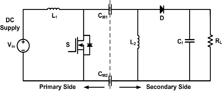
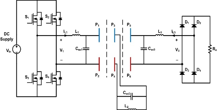
The main limitation of this topology is the transfer efficiency especially in long distance applications. When the number of repeater stage increases, the power loss in the system could increase drastically.
3.3.4. LCL Compensated Topology
Double-sided LCL compensated topology for electric vehicle charging was proposed in [37]. All the plates are vertically arranged to save space and placed close to each other to maintain a large coupling capacitance, as shown in Figure. 10. The series inductance L1 and L2 compensate only parts of the mutual capacitances CM1 and CM2 and the remaining parts are compensated by the LC networks. For each two plates at the same side, the coupling capacitance can be adjusted through regulating the distance and the system has good misalignment ability as the capacitance does not depend on misalignment. However, the system power is inversely proportional to coupling coefficient and it still requires larger inductors.
Figure 10. Double-sided LCL compensated circuit topology
The output power Pout is given in the following equation
3.3.5. LCLC Compensated Topology
The LCLC network as depicted in Figure 11. can attain unity power factor at both the input and the output side as well as the better coupling between the capacitors [39]. Also, the system efficiency will be high as the reactive power is eliminated.
Figure 11. Double-sided LCLC compensated topology
Fundamental harmonic approximation (FHA) method is used to analyze the circuit. Using superposition principle, components excited by the input voltage source and two parallel resonances are shown in Figure. 12. There is no current flowing through the inductor L1 and L2. The inductor Ls and the capacitor C2 form the first resonance which is expressed as,
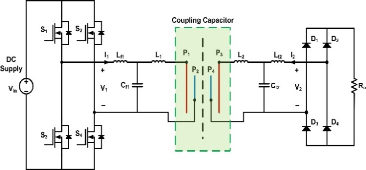
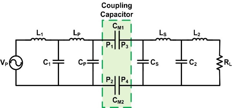
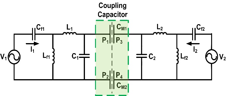
where ⍵0 is the switching frequency.
The capacitors CM1, CM2, Cp and Cs form an equivalent capacitance at the primary side which can be written as,
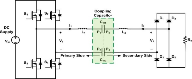
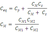
In Figure.12, the voltage on C2 is caused due to the capacitive coupling which can be written as,
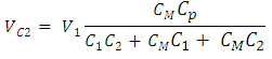
The output current (-I2) to the load is,
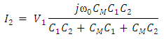
Similarly, the input current, I1 can be found as,
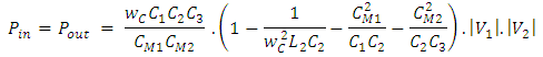
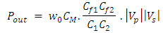
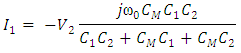
From above two equations, we observed that the input current I1 is 900 lagging V2 and the V1 is also lagging –I2 by 900. So the input voltage V1 is in phase with the input current I1.
The power transferred, Pout is,
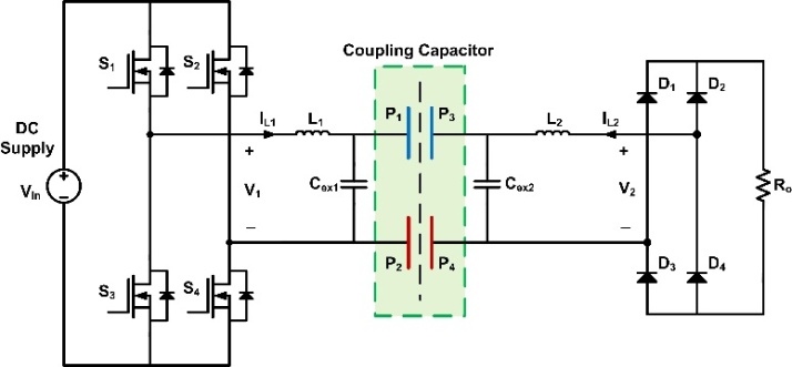
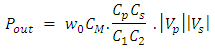
The main advantage of double-sided LCLC compensation circuit is that the system power is directly proportional to coupling coefficient. Moreover, in this topology without hampering coupling coefficient we can regulate system power through the circuit parameter design [40]. So, for efficiency consideration high coupling coefficient can be maintained fulfilling the power requirements. Again, as like the LC compensation circuit in this topology also we can reduce the resonant inductances L1 and L2 significantly by the help of the external capacitors Cex1 and Cex2.
The disadvantage of this topology is its complexity. The system cost, weight as well as power loss is increased due to the presence of eight passive components in the circuit which eventually affects the system efficiency.
3.3.6. CLLC Compensated Topology
In this paper [40], the CLLC compensation topology is proposed to reduce the required inductance value, as shown in Figure. 12.
Figure 12. CLLC compensated circuit topology
The CLLC compensation can slightly reduce the size of the compensation inductor. The reduction of the resonant inductances along with good misalignment ability at a reasonable air gap distance are the major advancements in the CPT technology created by this CLLC-compensated CPT system.

4. Comparison among Full-bridge Inverter-based Compensation Topologies

Table 2 will give a clear view of the comparison of full-bridge inverter-based compensation topologies in terms of output power, air gap distance, switching frequency, efficiency and complexity.
Table 2. Comparison among different topologies based on inverter-based topology for CPT system
     

5. Comparison between CPT and IPT System

The design of the compensation circuits for the IPT and CPT systems are analogous as the main focus of the compensation circuits is to establish resonances with the coupler. For IPT systems resonance can be achieved by using capacitive matching networks, whereas, in case of CPT systems inductive compensations are used. Compared to the IPT systems, the main advantages of the CPT systems are their low cost and weight, negligible eddy current loss and good performance in case of misalignment.
To increase the magnetic coupling between the two coils of an IPT system, a large amount of Litz-wire is used which increases the cost and weight of the system. The cost and weight increase even further if ferrite cores are used at the primary and secondary sides to increase the magnetic coupling. However, in a CPT system, the cost and weight are much lower as the capacitive coupler contains only several pieces of metal plates. In [42], capacitive coupler was designed using aluminium sheets with a thickness of only 2 mm which was sufficient to transfer 2.4 kW of power.
As the IPT system utilizes magnetic fields to transfer power, eddy current loss is prominent in the presence of nearby metals. Due to the circulating eddy currents causes the temperature of the nearby metal surfaces to increase significantly. For applications such as electric vehicle charging, the system power can increase up to tens of KWs causing the magnetic fields to generate large amount of heat in the nearby metal objects. On the other hand, eddy current loss is negligible in case of CPT systems as the power is transferred using electric fields.
Researches have shown that in case of misalignment, the power transfer capability of CPT systems is better compared to the IPT systems. In [68]; it was shown that a CPT system with metal plates of dimension 610 mm x 610 mm, can maintain the power level to 89.4% compared to the well aligned case with 300 mm misalignment. An inductive coupler having a dimension of 600 mm x 800 mm was considered for an
IPT system in [43]; where the transferred power level was 56% of the well aligned case with a 310 mm misalignment.
Therefore, it is evident that for similar dimensions of the coupling network, the IPT system is less efficient in transferring power at the receiving side in case of misalignment. These drawbacks in the IPT systems encouraged the researchers in the development of the CPT systems for wireless power transfer.

6. Conclusions

The concept of wireless power transfer technology (WPT) associated with capacitive power transfer (CPT) system has been identified as one of the most capable technology which has the ability to transfer power wirelessly with negligible losses and it also reduces the shortcomings related to the use of power cables. This paper reviews and explains different CPT system along with their compensation topologies and also compares the output characteristics like switching frequency, output power level and efficiency of those topologies and shows their suitableness in electric vehicle charging applications.
It is seen from the comparison that the LC compensator is very adaptable in high power and short distance applications but the modified LLC compensator is the one of the dominant compensation circuit which is accessible for short distance application due to its flexibility in operation but they are not suitable for long distance applications. Double sided LCLC is very efficient in long distance transmission as they reduce the voltage across the capacitive plates in a suitable range. They can be used for applications in power levels from watts to kilowatts range. Although these topologies possess high efficiencies but they have large air-gap and under misalignment conditions between the coupling plates. The CLLC compensation on the other hand has decent misalignment ability at a reasonable air gap distance due to reduction in its inductor size which is a major progress in CPT technology. In this paper the advancement and introduction of different CPT system and their compensation topologies have been summarized in a symmetric manner which is helpful to establish research framework of compensated topologies for capacitive power transfer for future applications. The drawbacks of each topology are also included which would help in modelling and improving the topologies for the further research.

7. Future Work

Recently, CPT has garnered much attention among the researchers due to several advantages it offers compared to the IPT system. However, there are some drawbacks persisting which need to be overcome. First, the power density of the CPT system is lower than the IPT system. Increasing the plate voltage and the switching frequency can provide the desired power density. Therefore, compensation topology can be optimized to increase these parameters to enhance the overall power density in future research. Moreover, the electric field is challenging to be shielded by the CPT system. So, more effort and study should be carried away in order to improve the electric field shielding system so that it should be safe for the human being.

References

[1]  A. Ram Rakhyani, S. Mirabbasi, and M. Chiao, “Design and optimization of resonance-based efficient wireless power delivery systems for biomedical implants”, Biomedical Circuits and Systems, IEEE Transactions on, vol. 5, no. 1, pp. 4863, Feb 2011.
[2]  S. Li, W. Li, J. Deng, and C. C. Mi, “A double-sided LCC compensation network and its tuning method for wireless power transfer”, IEEE Trans. Veh. Technol., vol. 64, no. 6, pp. 112, Jun. 2015.
[3]  Deepa Vincent, Phuoc Huynh Sang, and Sheldon S. Williamson, “Feasibility Study of Hybrid Inductive and Capacitive Wireless Power Transfer for Future Transportation”, Transportation Electrification Conference and Expo (ITEC), 2017 IEEE.
[4]  J. Dai and D. Ludois, “A Survey of Wireless Power Transfer and a Critical Comparison of Inductive and Capacitive Coupling for Small Gap Applications”, IEEE Trans. Power Electron., vol. 30, pp. 6011-6014, 2015.
[5]  J. Dai and D. Ludois, “Capacitive Power Transfer Through a Conformal Bumper for Electric Vehicle Charging”, IEEE Trans. Power Electron., vol. 30, no. 11, pp. 6017-6029, 2015.
[6]  C. Liu, A.P. Hu, N.C. Nair, “Modelling and Analysis of a Capacitively Coupled Contactless Power Transfer System”, IET Power Electron., vol. 4, no. 7, pp. 808-815, 2011.
[7]  L. Huang, A.P. Hu, A. Swain, “A Resonant Compensation Method for Improving the Performance of Capacitively Coupled Power Transfer”, IEEE Energy Conversion Congress and exposition (ECCE), pp.870-875, 2014.
[8]  S. Li, C. Mi, “Wireless Power Transfer for Electric Vehicle Applications”, IEEE Jour. of Emerg. and Selec. Top. on Power Electr. , vol. 3, no. 1 pp. 4-17, 2015.
[9]  F. Lu, H. Zhang, H. Hofmann, C. Mi, “A High Efficiency 3.3kW Loosely-Coupled Wireless Power Transfer System without Magnetic Material”, IEEE Energy Convers. Congr. Expo. (ECCE), pp. 2282-2286, 2015.
[10]  E.Culurciello, Andreou, “A. Capacitive Inter-Chip Data and Power Transfer for 3-D VLSI”, IEEE Trans. Circuit Syst. II, Vol. 53, pp. 13481352, 2006.
[11]  A. Sodagar, P. Amiri, “Capacitive Coupling for Power and Data Telemetry to Implantable Biomedical Microsystems”, IEEE Conference on Neural Engineering, Antalya, Turkey, 29 April 2 May 2009.
[12]  R. Jegadeesan, K. Agarwal, Y. Guo, S. Yen, N. Thakor, “Wireless Power Delivery to Flexible Subcutaneous Implants Using Capacitive Coupling”, IEEE Trans. Microw. Theory Tech., vol. 65, pp. 280-292, 2017.
[13]  D. Shmilovitz, A. Abramovitz and I. Reichman, “Quasi-Resonant LED Driver with Capacitive Isolation and High PF”, IEEE J. Emerg. Sel. Top. Power Electron., vol. 3, pp. 633641, 2015.
[14]  K. Wang, S. Sanders, “Contactless USBA Capacitive Power and Bidirectional Data Transfer System”, IEEE Applied Power Electronics Conference and Exposition, pp. 13421347, USA, 1620 March 2014.
[15]  T. Mostafa, A. Muharam and R. Hattori, “Wireless Battery Charging System for Drones via Capacitive Power Transfer”, IEEE Workshop on Emerging Technologies: Wireless Power Transfer, pp. 16, China, 2022 May 2017.
[16]  A.P. Hu, C. Liu and H. Li,“A novel Contactless Battery Charging System for Soccer Playing Robot”, International Conference on Mechatronics and Machine Vision in Practice, pp. 646650, Auckland, New Zealand, 24 December 2008.
[17]  Hua Zhang, Fei Lu, Heath Hofmann and Chris Mi, “A Loosely Coupled Capacitive Power Transfer System with LC Compensation Circuit Topology”, IEEE Energy Covers. Congr. Expo. (ECCE), pp. 1-5, 2016.
[18]  J. Dai, S. Hagen, D. Ludois and I. Brown, “Synchronous generator brushless field excitation and voltage regulation via capacitive coupling through journal bearing”, IEEE Trans. Ind. Appl., vol. 4, pp. 3317-3326, 2017.
[19]  Fei Lu, Hua Zhang and Chris Mi, “A Review on the Recent Development of Capacitive Wireless Power Transfer Technology”, Energies, vol. 10, pp. 1752, 2017.
[20]  I. Lee, J. Kim and W. Lee, “A high-efficient low-cost converter for capacitive wireless power transfer systems”, Energies, vol. 10, pp. 1473, 2017.
[21]  J. Dai and D. Ludois, “Single active switch power electronics for kilowatt scale capacitive power transfer”, IEEE J. Emerg. Sel. Top. Power Electron., vol. 3, pp. 315-323, 2016.
[22]  L. Huang, A.P Hu and A. Swain, “A resonant compensation method for improving the performance of capacitively coupled power transfer system”, IEEE 2014 Energy Conversion Congress and Exposition, pp. 870875, Pittsburgh, PA, USA, 2014.
[23]  B. Choi, D. Nguyen, S. Yoo, J. Kim and C.T. Rim, “A novel source-side monitored capacitive power transfer system for contactless mobile charger using class-E converter”, IEEE 79th Vehicular Technology Conference, pp. 15, Seoul, Korea, 2014.
[24]  R. Narayanamoorthi, A.V. Juliet, B. Chokkalingam, S. Padmanaban and Z.M. Leonowicz, “Class E power amplifier design and optimization for the capacitive coupled wireless power transfer system in biomedical implants”, Energies, vol. 10, pp. 1409, 2017.
[25]  D. Ludois, J. Reed and K. Hanson, “Capacitive power transfer for rotor field current in synchronous machines”, IEEE Trans. Power Electron. , vol. 27, pp. 46384645, 2012.
[26]  D. Ludois, M. Erickson and J. Reed, “Aerodynamic fluid bearings for translational and rotating capacitors in non-contact capacitive power transfer systems”, IEEE Trans. Ind. Appl., vol. 50, pp. 10251033, 2014.
[27]  Fei Lu, Hua Zhang, Heath Hofmann and Chris Mi, “A Loosely Coupled Capacitive Power Transfer with LC Compensation Topology”, IEEE Energy Convers. Congr. Expo (ECCE), pp. 1-5, 2016.
[28]  Fei Lu, Hua Zhang, Heath Hofmann and Chris Mi, “A Double-Sided LC Compensation Circuit for Loosely-Coupled Capacitive Power Transfer”, IEEE Trans. Power Electron., Vol. 33, no. 3, pp. 1633 - 1643, 2017.
[29]  M. Kusunoki, D. Obara and M. Masuda, “Wireless Power Transfer via Electric Field Resonance Coupling”, IEEE Asia-Pacific Microwave Conf. (APMC), pp. 1360-1362, 2014.
[30]  R.D Fernandes, J.N. Matos and N.B. Carvalho, “Wireless Power Transmission based on Resonant Electrical Coupling”, IEEE European Microwave Conference (EuMC), pp. 17- 20, 2014.
[31]  T. Komaru and H. Akita, “Positional Characteristics of Capacitive Power Transfer as a Resonance Coupling System”, IEEE Wireless Power Transfer conference. (WPTC)., pp. 218-221, 2013.
[32]  M. Kusunoki, D. Obara and M. Masuda, “Wireless power transfer via electric field resonance coupling”, In Proceedings of the IEEE Asia-Pacific Microwave Conference (APMC), Sendai, Japan, 47 November, pp. 13601362, 2014.
[33]  R.D. Fernandes, J.N. Matos and N.B. Carvalho, “Wireless power transmission based on resonant electrical coupling”, In Proceedings of the IEEE European Microwave Conference (EuMC), Rome, Italy, 69 October, pp. 1720, 2014.
[34]  B. Regensburger, A. Kumar, S. Sinha, K. Doubleday, S. Pervaiz, Z. Popovic and K. Afridi, “High performance large air-gap capacitive wireless power transfer system for electric vehicle charging”, In Proceedings of the IEEE 2017 Transportation Electrification Conference and Expo, Chicago, IL, USA, 2224 June, pp. 638643, 2017.
[35]  Hua Zhang, Fei Lu, Heath Hofmann and Chris Mi, “An LC Compensated Electric Field Repeater for Long Distance capacitive Power Transfer”, Energy Convers. Congr. Expo (ECCE), 2016.
[36]  T. Duerbaum, “First harmonic approximation including design constraints”, Telecommunications Energy Conference, INTELEC. Twentieth International, pp. 321328, 1998.
[37]  Hua Zhang, Fei Lu, Heath Hofmann and Chris Mi, “A 4-Plate Compact Capacitive Coupler Design and LCL-Compensated Topology for Capacitive Power Transfer in Electric Vehicle Charging Applications”, IEEE Trans. Power Electron., vol. 31, no. 12, pp. 8541-8551, 2016.
[38]  Deepak Rozario, Najath Abdul Azeez, and Sheldon S. Williamson, “Modified Resonant Converters for Capacitive Power Transfer Systems used for Battery Charging Applications”, IEEE Transportation Electrification Conference and Expo, USA, 2016.
[39]  Fei Lu, Hua Zhang, Heath Hofmann and Chris Mi, “A Double-sided LCLC-Compensated Capacitive Power Transfer System for Electric Vehicle Charger”, IEEE Trans. Power Electrn., Vol. 30, no. 11, pp. 6011-6014, 2015.
[40]  Fei Lu, Hua Zhang, Heath Hofmann and Chris Mi, “A CLLC-Compensated High Power and Large Air-Gap Capacitive Power Transfer System for Electric Vehicle Charging Applications”, IEEE Appl. Power Electr. Conf. (APEC), pp. 1721-1725, 2016.
[41]  Fei Lu, Hua Zhang and Chris Mi,“A Two-Plate Capacitive Wireless Power Transfer System for Electric Vehicle Charging Applications” IEEE Transactions on Power Electronics, vol. 33, pp. 964 - 969, 2018.
[42]  Fei Lu, Hua Zhang, Heath Hofmann and Chris Mi, “A double-sided LCLC-compensated capacitive power transfer system for electric vehicle charging,” IEEE Trans. Power Electron. Vol. 30, pp. 6011–6014, 2015.
[43]  S. Li, W. Li, J. Deng, T.D. Nguyen and C. Mi, “A double sided LCC compensation network and its tuning method for wireless power transfer”, IEEE Trans. Veh. Technol., vol. 64, pp. 2261–2273, 2015.