Mohammed S. Ahmed
Department of Computers Techniques Engineering, Dijlah University College, Baghdad, Iraq
Correspondence to: Mohammed S. Ahmed, Department of Computers Techniques Engineering, Dijlah University College, Baghdad, Iraq.
| Email: |  |
Copyright © 2019 The Author(s). Published by Scientific & Academic Publishing.
This work is licensed under the Creative Commons Attribution International License (CC BY).
http://creativecommons.org/licenses/by/4.0/

Abstract
Radio-Frequency Identification (RFID) is an automatic identification technology that enables tracking of people and objects. Both identity and location are generally key information for indoor and outdoor services. An obvious and interesting method to obtain these two types of data is to localize RFID tags attached to devices or objects or carried by people. However, signals in indoor environments are generally harshly impaired and tags have very limited capabilities which pose many challenges for positioning them. While in outdoor environments are generally simple to detect and locate. The importance of outdoor applications could be minimized to most important field which is accident avoidance. Accidents, like car crushing and hit and run could be minimized if the technology of RFID used as tags locate it in people and readers in the cars which force the car to stop before the accident or give a buzz to the people to avoid the accident. From that perspective design and testing a receiver device for the driver and Tag device for the person or object and achieve connection between the two device using RFID.
Keywords:
Radio-Frequency Identification (RFID), Collision Avoidance, Collision warning system, RFID system, Transmits, Receiver
Cite this paper: Mohammed S. Ahmed, Application of RFID Systems to Collision Avoidance, Electrical and Electronic Engineering, Vol. 9 No. 1, 2019, pp. 1-8. doi: 10.5923/j.eee.20190901.01.
1. Introduction
Today RFID is a generic term for technologies that use radio waves to automatically identify people or objects. There are several methods of identification [1]. Recently the research on RFID is increasing rapidly because of the invention of this technology may change mankind's present life style. The RFID system has already been widely used on supply chain management, access control to buildings…etc. RFID is the reading of physical tags on single products, cases, pallets, or re-usable containers that emit radio signals to be picked up by reader devices. These devices and software must be supported by a sophisticated software architecture that enables the collection and distribution of location-based information in near real time. The complete RFID picture combines the technology of the tags and readers with access to global standardized databases, ensuring real time access to up-to-date information about relevant products at any point in the supply chain. Tags contain a unique identification number called an Electronic Product Code (EPC), and potentially additional information of interest to manufacturers, healthcare organizations, military organizations, logistics providers, and retailers, or others that need to track the physical location of goods or equipment. All information stored on RFID tags accompanies items as they travel through a supply chain or other business process. All information on RFID tags, such as product attributes, physical dimensions, prices, or laundering requirements, can be scanned wirelessly by a reader at high speed and from a distance of several meters [2]. The aim of this paper is to investigate the possibility of using the RFID technology to design a system for Collision Avoidance.
1.1. RFID Applications
Also intended for practitioners who, as users, wish to or need to obtain as comprehensive and detailed an overview of the various technologies, the legal framework or the possible applications of RFID are:1. RFID systems have been deployed in limited numbers for years; two of Security, ticketing, and access control2. Lifetime item identification3. Transient carrier labelling4. Animal and specimen identification5. The most predominant have been in the form of toll-road collection transponders and security badges.6. Supply chain logistics7. Product authentication8. Tracking and traceability9. Airline baggage handling [3].RFID systems have been deployed in limited numbers for years; two of the most predominant have been in the form of toll-road collection transponders and security badges. Toll-road authorities around the country have equipped drivers with transponders that are connected to their credit cards. This allows them to pay their tolls at 40 mph rather than stopping to throw quarters into a basket and slowing the flow of traffic. Security badges have been equipped with RFID chips to allow centralized control of access to facilities and specific rooms within buildings. These can also be used to track the locations of people in a facility by identifying the door they last passed through. Today, RFID has the potential for applications in virtually any area of industry, commerce, and services where items are handled and associated data collected and processed. These include: [4]Ÿ Supply chain logistics;Ÿ Product authentication;Ÿ Tracking and traceability;Ÿ Security, ticketing, and access control;Ÿ Lifetime item identification;Ÿ Transient carrier labelling;Ÿ Animal and specimen identification;Ÿ Airline baggage handling.
1.2. History of RFID [4-6]
Although the emergence of RFID technology is a recent development, the ideas behind it have been building for decades. Throughout the last century, scientists and researchers have been studying the effects of reflected backscatter in order to harness this potential technique for revolutionizing applications. Interest in this field began not for commercial uses, but rather for military purposes. During the Second World War, the need for passive and covert means of transmitting and receiving information became an area of particular interest for countries with strong military agendas. In 1945 a soviet scientist named Leon Theremin invented a covert listening device that retransmitted incident radio waves with audio information modulation. Similarly, in 1939, the British government saw the potential in this technology, and applied it to aid them in aerial combat. Their technology named the “Identify Friend or Foe System” or IFF used an early predecessor for RFID and used to label their aircrafts as a means to determine if an incoming plane belonged to them. A transponder was placed on each of the British aircrafts, and upon being. Interrogated by an incoming electromagnetic wave, would transmit an appropriate signal to identify itself as friendly. This system is often attributed to being the first obvious use of RFID technology. In 1948, a ground breaking publication written by a research scientist named Harry Stockman called "Communication by Means of Reflected Power," was the first article that explored the use of backscatter as a means for information transmission. This article investigated the possibilities presented by this technology and the problems associated with it. Unfortunately, at the time it was written, science had not evolved to a point where the deployment of this technique was feasible. In fact, Stockman himself states in his conclusions that, “considerable research and development work has to be done before the remaining basic problems in reflected-power communication are solved, and before the field of useful applications is explored". Regardless, for the next thirty years researches used this paper as a crucial reference to develop solutions for these problems and make RFID a practical technology.
1.3. Aim of Work
Implementation and designing a system installed in the cars for future accident warning.
2. Fundamental Operating Principles
These principles describe the basic interaction between transponder and reader, in particular the power supply to the transponder and the data transfer between transponder and reader.
2.1. Bit Transponder (EAS)
A bit is the smallest unit of information that can be represented and has only two states: 1 and 0. This means that only two states can be represented by systems based upon a 1-bit transponder: ‘transponder in interrogation zone’ and ‘no transponder in interrogation zone’. Despite this limitation, 1-bit transponders are very widespread their main field of application is in electronic anti-theft devices in shops (EAS, electronic article surveillance) [4, 6]. This transponder consists of antenna of a ‘reader’ or interrogator, the security element or tag, and an optional deactivation device for deactivating the tag after payment. Some systems also incorporate an activator, which is used to reactivate the security element after deactivation. The main performance characteristic for all systems is the recognition or detection rate in relation to the gate width (maximum distance between transponder and interrogator antenna) [4]. This system can be classified into:1. Radio frequency2. Microwaves3. Frequency divider4. Electromagnetic5. Acoustomagnetic
2.1.1. Radio Frequency
The radio frequency (RF) procedure is based upon LC resonant circuits adjusted to a defined resonant frequency fR [4]. These systems employ coils etched between foils in the form of stick-on labels. To ensure that the damping resistance does not become too high and reduce the quality of the resonant circuit to an unacceptable level. The reader (detector) generates a magnetic alternating field in the radio frequency range (Figure 1) shows the operating principles of EAS radio frequency procedure. If the LC resonant circuit is moved into the vicinity of the magnetic alternating field, energy from the alternating field can be induced in the resonant circuit via its coils (Faraday’s law). If the frequency fG of the alternating field corresponds with the resonant frequency fR of the LC resonant circuit the resonant circuit produces a sympathetic oscillation. The current that flows in the resonant circuit as a result of this acts against its cause, i.e. it acts against the external magnetic alternating field. This effect is noticeable as a result of a small change in the voltage drop across the transmitter’s generator coil and ultimately leads to a weakening of the measurable magnetic field strength. A change to the induced voltage can also be detected in an optional sensor coil as soon as a resonant oscillating circuit is brought into the magnetic field of the generator coil [4, 6].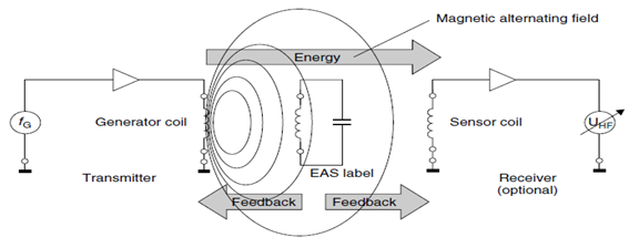 | Figure 1. Operating principles of EAS radio frequency procedure |
The relative magnitude of the changes in voltage at the generator and sensor coils is generally very low and thus difficult to detect. However, the signal should be as clear as possible so that the security element can be reliably detected. This is achieved using a bit of a trick: the frequency of the magnetic field generated is not constant, it is ‘swept’. This means that the generator frequency continuously crosses the range between minimum and maximum. The frequency range available to the swept systems is 8.2MHz ±10% [6]. Whenever the swept generator frequency exactly corresponds with the resonant frequency of the resonant circuit (in the transponder), the transponder begins to oscillate, producing a clear dip in the voltages at the generator and sensor coils [4]. Because the tags are not removed at the till, they must be altered so that they do not activate the anti-theft system. To achieve this, the cashier places the protected product into a device — the deactivator — that generates a sufficiently high magnetic field that the induced voltage destroys the foil capacitor of the transponder. The capacitors are designed with intentional short-circuit points, so-called dimples. The breakdown of the capacitors is irreversible and detunes the resonant circuit to such a degree that this can no longer be excited by the sweep signal [8].
2.1.2. Microwaves
Transponders of this type cast in plastic (hard tags) are used mainly to protect textiles. The tags are removed at the till when the goods are paid for and they are subsequently reused. (Figure 2) shows a Basic circuit and typical construction format of a microwave tag transponder being placed within the range of a microwave transmitter operating at 2.45 GHz [4, 6]. The second harmonic of 4.90 GHz generated in the diode characteristic of the transponder is re-transmitted and detected by a receiver, which is adjusted to this precise frequency. The reception of a signal at the frequency of the second harmonic can then trigger an alarm system.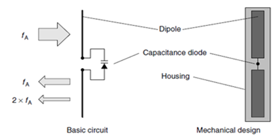 | Figure 2. Basic circuit and typical construction format of a microwave tag |
EAS systems in the microwave range exploit the generation of harmonics at components with nonlinear characteristic lines (e.g. diodes). The harmonic of a sinusoidal voltage A with a defined frequency fA is a sinusoidal voltage B, whose frequency fB is an integer multiple of the frequency fA. The sub harmonics of the frequency fA are thus the frequencies 2fA, 3fA, 4fA etc. The Nth multiple of the output frequency is termed the Nth harmonic (Nth harmonic wave) in radio-engineering; the output frequency itself is termed the carrier wave or first harmonic [6]. In principle, every two-terminal network with a nonlinear characteristic generates harmonics at the first harmonic. In the case of nonlinear resistances, however, energy is consumed, so that only a small part of the first harmonic power is converted into the harmonic oscillation. Under favourable conditions, the multiplication of f to n × f occurs with an efficiency of η = 1/n2. However, if nonlinear energy storage is used for multiplication, then in the ideal case there are no losses [9].
2.1.3. Frequency Divider
This procedure operates in the long wave range at 100–135.5 kHz. The security tags contain a semiconductor circuit (microchip) and a resonant circuit coil made of wound enamelled copper. The resonant circuit is made to resonate at the operating frequency of the EAS system using a soldered capacitor. These transponders can be obtained in the form of hard tags (plastic) and are removed when goods are purchased [6].The microchip in the transponder receives its power supply from the magnetic field of the security device. The frequency at the self-inductive coil is divided by two by the microchip and sent back to the security device. The signal at half the original frequency is fed by a tap into the resonant circuit coil as shown in (Figure 3) the Basic circuit diagram of the EAS frequency division procedure: security tag (transponder) and detector (evaluation device) [10].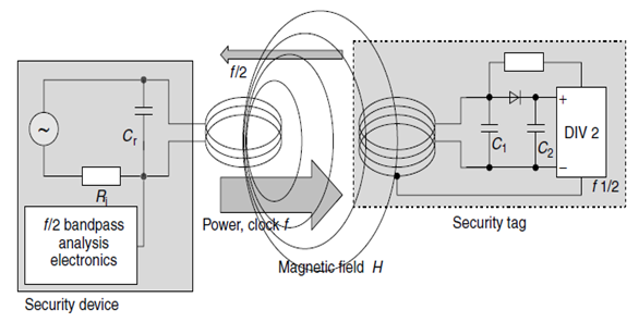 | Figure 3. Basic circuit diagram of the EAS frequency division procedure: security tag (transponder) and detector (evaluation device) |
2.1.4. Electromagnetic
Electromagnetic types operate using strong magnetic fields in the NF range from 10Hz to around 20 kHz. The security elements contain a soft magnetic amorphous metal strip with a steep flanked hysteresis curve. The magnetisation of these strips is periodically reversed and the strips taken to magnetic saturation by a strong magnetic alternating field. The markedly nonlinear relationship between the applied field strength H and the magnetic flux density B near saturation, plus the sudden change of flux density B in the vicinity of the zero crossover of the applied field strength H, generates harmonics at the basic frequency of the security device, and these harmonics can be received and evaluated by the security device [6]. The electromagnetic type is optimised by superimposing additional signal sections with higher frequencies over the main signal. The marked nonlinearity of the strip’s hysteresis curve generates not only harmonics but also signal sections with summation and differential frequencies of the supplied signals [6]. For deactivation, the tags are coated with a layer of hard magnetic metal or partially covered by hard magnetic plates. At the till the cashier runs a strong permanent magnet along the metal strip to deactivate the security elements. This magnetizes the hard magnetic metal plates. The metal strips are designed such that the remanence field strength of the plate is sufficient to keep the amorphous metal strips at saturation point so that the magnetic alternating field of the security system can no longer be activated [6].The tags can be reactivated at any time by demagnetisation. The process of deactivation and reactivation can be performed any number of times [11].
2.1.5. Acoustomagnetic
The great advantage of this procedure is that the security system is not itself transmitting while the security element is responding and the detection receiver can thus be designed with a corresponding degree of sensitivity [4].In their activated state, acoustomagnetic security elements are magnetized, i.e. the above-mentioned hard magnetic metal strip has high remanence field strength and thus forms a permanent magnet. To deactivate the security element, the hard magnetic metal strip must be demagnetized. This detunes the resonant frequency of the amorphous metal strip so it can no longer be excited by the operating frequency of the security system. The hard magnetic metal strip can only be demagnetized by a strong magnetic alternating field with slowly decaying field strength. It is thus absolutely impossible for the security element to be manipulated by permanent magnets brought into the store by customers [6].If a security element is within the field of the generator coil this oscillates like a tuning fork in time with the pulses of the generator coil. The transient characteristics can be detected by an analysing unit [11]. (Figure 4) shows the Acoustomagnetic system comprising transmitter and detection device (receiver).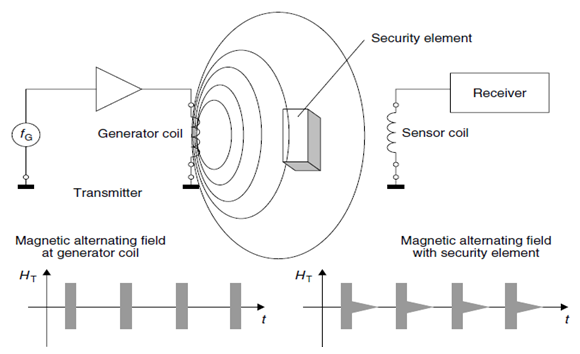 | Figure 4. Acoustomagnetic system comprising transmitter and detection device |
2.2. Full and Half Duplex Procedure
The transponders in this type use an electronic microchip as the data-carrying device. This has a data storage capacity of up to a few kilobytes. To read from or write to the data-carrying device it must be possible to transfer data between the transponder and a reader. This transfer takes place according to one of two main procedures [6]. In the half duplex procedure (HDX) the data transfer from the transponder to the reader alternates with data transfer from the reader to the transponder. At frequencies below 30MHz this is most often used with the load modulation procedure, either with or without a subcarrier, which involves very simple circuitry. Closely related to this is the modulated reflected cross-section procedure that is familiar from radar technology and is used at frequencies above 100 MHz. Load modulation and modulated reflected cross-section procedures directly influence the magnetic or electromagnetic field generated by the reader and are therefore known as harmonic procedures [4, 6]. In the full duplex procedure (FDX) the data transfer from the transponder to the reader takes place at the same time as the data transfer from the reader to the transponder. This includes procedures, in which data is transmitted from the transponder at a fraction of the frequency of the reader, i.e. a sub harmonic, or at a completely independent, i.e. an anharmonic, frequency [6].However, both procedures have in common the fact that the transfer of energy from the reader to the transponder is continuous, i.e. it is independent of the direction of data flow [6].
2.3. Sequential Procedure
If the transmission of data and power from the reader to the data carrier alternates with data transfer from the transponder to the reader, this called a sequential procedure (SEQ) [12]. The transfer of energy from the transponder to the reader takes place for a limited period of time only (pulse operation → pulsed system). Data transfer from the transponder to the reader occurs in the pauses between the power supply to the transponder [6] (Figure 5) shows the Representation of full duplex, half duplex and sequential systems over time. The data transfer from the reader to the transponder is termed downlink, and the data transfer from the transponder to the reader is termed uplink.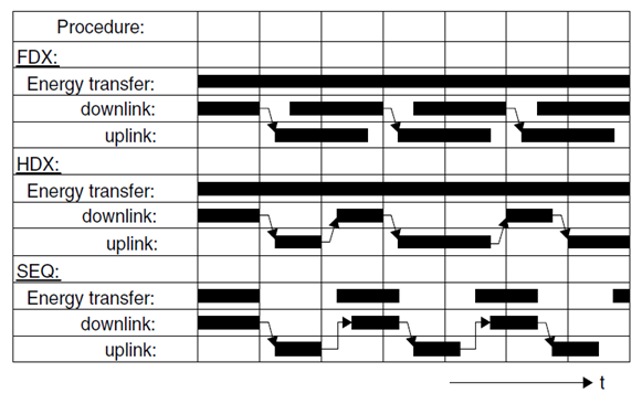 | Figure 5. Representation of full duplex, half duplex and sequential systems over time. Data transfer from the reader to the transponder is termed downlink, while data transfer from the transponder to the reader is termed uplink |
3. System Design
The purpose of every collision warning system is to alert drivers about the existence of unexpected or unseen vehicles or humans. In producing an effective product, the system should provide a reliable real time warning system that is not only capable of warning the driver, but also gives the driver time to react, as well.In this chapter, it will be describing the work of the system (circuits) that give the required real time including the design and test for it, for this reason an idea was created for sender (transmitting) and sensor (receiver) by using RFID waves that carry the signal from transmitting device to the receiver by proving the idea of connection, which have been proved in these circuits.
3.1. System Requirements
The two circuits are:1. The sensor device (Receiver)2. The antenna device (Transmits)
3.1.1. The Sensor Device (Receiver)
The sensor it is devices that receive the radio frequency signal (wireless RFID) from transceiver and then give a warning signal by digital screen or light of a led to the driver to stop or limited his speed of driving to avoid the car crash. So that how collision avoidance detected?The circuit contains the following components:1. ResistorsR1=4.685KΩ, R2=65KΩ, R3=7.5KΩ, R4=0.682KΩ, R5=10KΩ, R6=462KΩ, R7=46.3KΩ, R8=2MΩ, R9=5MΩ, R10=1MΩ.2. Two Diodes3. Capacitors4. C1=4µf, C2=222µf, C3=39µf, C4=681µf, C5=5µf, C6=220µf/10v, C7=27µf, C8=1µf/50v.5. Two IC (IC1=TC4060BP, IC2=DO-35)6. Coils7. Transistors (Q1=S9014C 331, Q2=S9018H 331)8. AND TX.In TC40690Bp contains six circuits of inverters. Since the internal circuit is composed of a single stage inverter, this is suitable for the applications of CR oscillator circuits, crystal oscillator circuits and linear amplifiers in addition to its application as inverters. Because of one stage gate configuration, the propagation time has been reduced. This IC used as an amplifier. In Q1 is used for general purpose switching and amplification and Q2is AM/FM Amplifier, Local Oscillator of FM/VHF Tuner High Current Gain Bandwidth Product fT=1.1 GHz High frequency low noise amplifier application VHF band amplifier application.The DO-35 is The CFPO-DO series are a range of Super Single Oven OCXO’s designed as a compact and smart frequency source/time keeping reference for all synchronization systems including global positioning system (GPS) based equipment, in TX is SMD TCXO Sine wave Output signal, wide frequency range up to 500 MHz, Low phase noise. Design the receiver circuit using MultiSim program on PC and starting simulation as shown in (Figure 6), making the primary design test of the receiver circuit as shown in figure (Figure 7), after finishing the testing, The final design of the receiver circuit as shown in figure (Figure 8).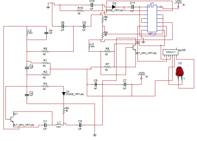 | Figure 6. The simulation of receiver circuit |
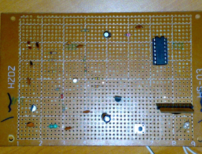 | Figure 7. The primary design test of the receiver circuit simulation |
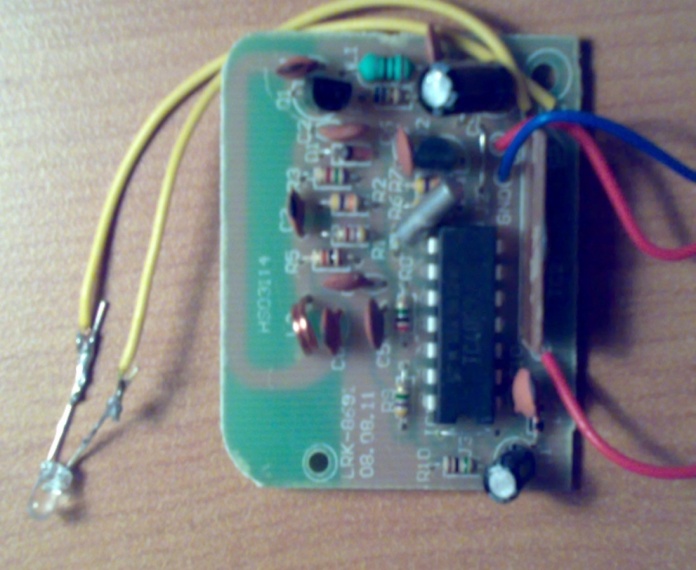 | Figure 8. The final design of the receiver circuit |
3.1.2. The Antenna Device (Transmits)
The antenna it is a device that his task is to transmit the signal (wireless RFID) to a car in order to warn the driver to avoid collision, for that the transmitter antenna is designed as follow, the circuit contain:1. Resistors R1=100Ω, R2=28KΩ, R3=22KΩ, R4=218KΩ, R5=10KΩ.2. Capacitors C1=4µf, C2=6µf, C3=5µf, C4=8µf, C5=222µf, 3. Coils4. Tx And Switch5. Transistors (Q1=S9018H331, Q2=S9014C331, Q3=S9014C331).In Q1 is AM/FM Amplifier, Local Oscillator of FM/VHF Tuner High Current Gain Bandwidth Product fT=1.1 GHz (Type) (High frequency low noise amplifier application VHF band amplifier application).In Q2 & Q3 it used for General purpose switching and amplification, in coils one of them is an adjustable coil frequencies could be changed. In TX is SMD TCXO Sine wave Output signal sine wave, Wide frequency range up to 500 MHz, Low phase noise. Design the transmitter circuit using MultiSim program on computer and starting simulation as shown in (Figure 9), making the primary design test of the transmitter circuit and starting testing the circuit as shown in figure (Figure 10), The final design of the transmitter circuit as shown in figure (Figure 11).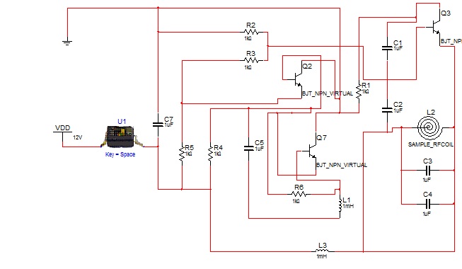 | Figure 9. The simulation of antenna circuit |
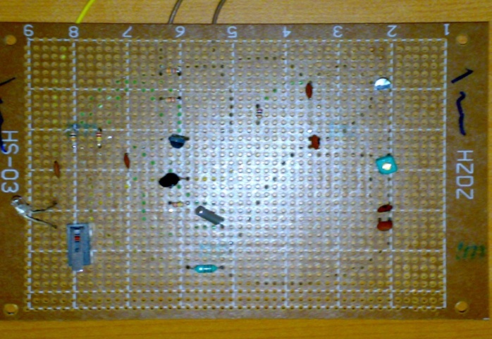 | Figure 10. The primary design test of the transmitter circuit |
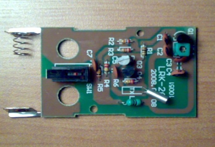 | Figure 11. The final design of the transmitter circuit |
4. The Results
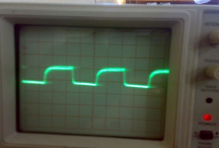
The results of this work have been implemented for both transmitter and receiver circuits.This receiver detects the signal from the antenna, the result of this detection will make the circuit to work by warning the driver the presence of an object in front of the vehicle or behind it (Figure 12) shows The output signal from receiver circuit with Voltage =1v/div and Time = 0.5msec/div, (Figure 13) shows The output signal form transmitter circuit with Voltage =0.5 v/div and Time=5µs.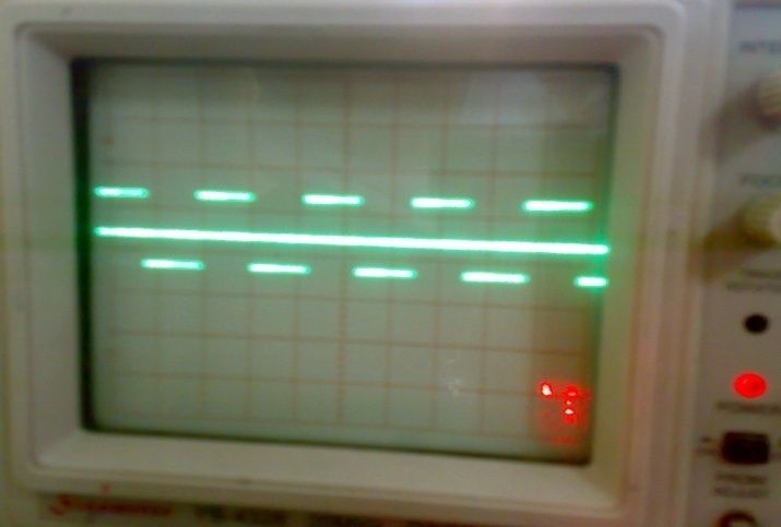 | Figure 12. The output from receiver circuit with Voltage =1v/div and Time = 0.5msec/div |
 | Figure 13. The output form transmitter circuit with Voltage =0.5 v/div and Time=5µs |
The output frequency of this circuit is 0.8 MHz this circuit attached to the object and keep sending it signal until a receiver detect it. The use for this signal is to warn the driver to avoid an expected accident. (Figure 14) and (Figure 15) shows The Full RFID System Reader and the Tag (transmitter) as They Work in (primary design) and (final design) and using LED indicator lights to show the receiver had received the Tag (transmitter) signal and achieve connection between the two device in real time. 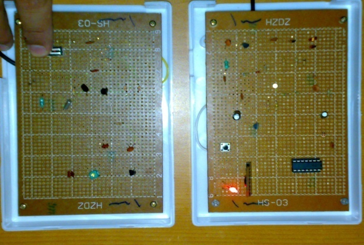 | Figure 14. Full RFID System Reader and the Tag as They Work (primary design) |
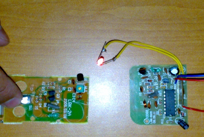 | Figure 15. Full RFID System Reader and the Tag as They Work (final design) |
5. Conclusions
From the results of this project the system has achieve connection and can be use as a warning system useful to avoid any collisions in general, humans in special.The drawback of it could be minimized into the following,1. This system can't estimate where the object is, (i.e.) the object might be in the side way and the car in the road, the possibilities of having a collision is minimized, but the reader will read the signal of the object and keep warning the driver.2. The warning system could be a light, sound or an immediate stop The light system which is LED should be in a position where the driver for certain could see it, same idea for the sound, the sound system should be loud enough to make sure that the drive is hearing it, but if there is a high record is playing, how he could hear it? The replacement here is the immediate stop, now the problem is, if the driver driving his car at a high speed, another type of collision will be happened which is rolling over or upside-down the car as a result of immediate stop.How could these problems have solved or avoided?The answer could be, by limiting the point of view of the detector to a certain angle where collisions might occur, and position the readers in the front of the car and in the back to avoid both collisions.The second problem could be solved by solving the relation between the speed of the car and the remaining distance between the car and the object, according to this relation the reader should create a decision to slow down the car gradually until it could stop when the object is near to it.
6. Future Work
1. Design a system capable of slowing down the car without rolling it over as a result of the speed.2. Design a system to limit the point of view of the reader where only the possible accident signals could be read.3. Installing the system in the car and connecting it to a microcontroller where decisions according to the situations could be made.4. Finding for the possibility of using this method to prevent collisions in flying cars in the future.
References
| [1] | "Radio Frequency Identification (RFID)", Automatic Identification and Data Collection at University of Pittsburgh, 2001. |
| [2] | Ting Zhang, Yuanxin Ouyang, Yang He, "Journal of Theoretical and Applied Electronic Commerce Research", Universidad de Talca, Chile, 2008. |
| [3] | Klaus Finkenzeller, "RFID handbook", Giesecke & Devrient GmbH, Munich, Germany, 2003. |
| [4] | Harvey Lehpamer, "RFID Design Principles", ARTECH HOUSE, INC., 2008. |
| [5] | C.M. Roberts, "Radio frequency identification (RFID)", Department of Information Sciences, Otago University, New Zealand, 2006. |
| [6] | Klaus Finkenzeller, "RFID handbook", Giesecke & Devrient GmbH, Munich, Germany, 2003. |
| [7] | Best S., “Antenna Polarization Considerations in Wireless Communications Systems,” Cushcraft Corporation, Manchester, NH, 2003. |
| [8] | Ergen, S. C., ZigBee/, Internal Report to Advanced Technology Lab of National Semiconductor, Berkeley, IEEE 802.15.4 Summary, CA, 2004. |
| [9] | Reed, J., "An Introduction to Ultra Wideband Communication Systems", Upper Saddle River, NJ: Prentice-Hall, 2005. |
| [10] | Miura, N., et al., “Analysis and Design of Inductive Coupling and Transceiver Circuit for Inductive Inter-Chip Wireless Superconnect,” IEEE J. of Solid-State Circuits, Vol. 40, No.4, April 2005. |
| [11] | Bennett, C. L., and Ross, G. F., “Time-Domain Electromagnetics and Its Applications,” Proc. IEEE, Vol. 66, No. 3, March 1978. |
| [12] | Nivi, B., et al., “Passive Wearable Electrostatic Tags: The Bodytag,” Cambridge, MA: Physics and Media, MIT Media Lab, September 12, 1997. |

 Abstract
 Reference
 Full-Text PDF
 Full-text HTML