Yasuyuki Okumura, Katsuyuki Fujii, Takumi Nagaya, Naoki Inagaki
Faculty of Science and Engineering, Nanzan University, Aichi, Japan
Correspondence to: Yasuyuki Okumura, Faculty of Science and Engineering, Nanzan University, Aichi, Japan.
| Email: |  |
Copyright © 2018 The Author(s). Published by Scientific & Academic Publishing.
This work is licensed under the Creative Commons Attribution International License (CC BY).
http://creativecommons.org/licenses/by/4.0/

Abstract
This paper proposes a novel method to measure the permeability of thin ferromagnetic sheets in a low frequency range using LCR meter; the proposal offers direct measurement of unprocessed sheets with simple apparatus. In conventional measurement schemes, the permeability of magnetic material is derived from the self-inductance of a cored inductor with a closed loop configuration and adequate thickness. In case of thin magnetic sheets, the toroidal core is made of many layers of the sheets cut into torus shapes. To avoid this process, this paper proposes to put metallic coil in the neighborhood of the magnetic sheet, and measure the inductance and the resistance of the coil. On the other hand, the electromagnetic field simulator approach determines the permeability by matching the measured inductance and resistance values of the same configuration. This paper also clarifies that the permeability value measured by the proposed method basically agrees with the actual value.
Keywords:
Permeability measurement, Thin ferromagnetic sheet, LCR meter
Cite this paper: Yasuyuki Okumura, Katsuyuki Fujii, Takumi Nagaya, Naoki Inagaki, Simple Permeability Measurement of Thin Ferromagnetic Sheets at Low Frequency Using LCR Meter, Electrical and Electronic Engineering, Vol. 8 No. 2, 2018, pp. 53-58. doi: 10.5923/j.eee.20180802.03.
1. Introduction
Ferromagnetic sheets are attracting a large amount of attention currently because they can shield electronic appliances from electromagnetic interference. Typical ferromagnetic materials are permalloy, amorphous alloy, ferrite, nickel, and neodymium magnet, where ferrite and amorphous alloy are often used in magnetic sheets for high and low frequencies, respectively. The flexibility and thinness allow the magnetic sheets to be processed into a wide range of shapes, and their high permeability broadens the application fields; near field communication [1], wireless power transfer [2-4] and RFID [5]. Wireless power transfer using magnetic resonant coupling is attracting particular attention because it is applicable to electric vehicles, home appliances, mobile terminals, and medical equipment. In magnetic resonant coupling, the transmitter and receiver coils are placed close to each other so that they become tightly coupled by the imposed magnetic field [6-8]. The metallic devices commonly installed near the coils interact with the magnetic field and cause power transfer loss. Placing ferromagnetic sheets between the coil and each metallic device reduces the interaction, and consequently suppresses the transfer loss. To design the power transfer circuits, the permeability of the ferromagnetic sheets in the low frequency band must be clarified. Since the manufacturers of the ferromagnetic sheets usually do not guarantee or even publish their products physical characteristics in the frequency band, the designers of power transfer circuits must measure the characteristics on their own. One of the most important parameters is the relative permeability, which is typically derived from the self-inductance of a cored magnetic material that has a closed loop configuration such as the toroidal core [9-11]. The conventional measurement method is to wind some wire around the core and use an impedance measuring instrument to evaluate the self-inductance across the ends of the wire. In case of thin magnetic sheets, the toroidal core must be manufactured by stacking many torus shapes cut from sheets.The aim of this paper is to develop a method of measuring the permeability of magnetic sheets without wasting the time and effort needed to manufacture a toroidal core by layering the cut out shapes. To measure permeability, this paper proposes to put a metallic coil in the neighborhood of the magnetic sheet, and evaluate the inductance and the resistance of the coil under the influence of the magnetic sheet. In addition, we use a electromagnetic field simulator to evaluate the inductance and resistance values in the same configuration while varying the parameter of relative permeability. Using these results, the permeability is determined to be that value that yields the best match between the measured inductance and resistance values and the simulated values. Tests of the proposed method show close agreement with the actual value.
2. Conventional Measurement Method
There are two standard measurement methods; both require the target material to shaped into a toroidal core with significant thickness. The reason is that this shape can be theoretically analyzed.
2.1. Wire Coil Inductance Method [10-12]
The self-inductance and the resistance across the ends of the wire around the magnetic core can be measured using an impedance measuring instrument, as shown in Figure 1. In addition, the self-inductance and the resistance are measured for the same circuit but without the magnetic core. By comparing these results, the real part of relative permeability  and the imaginary part
  are derived as follows;
 | (1) |
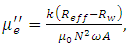 | (2) |
where k: average magnetic path length of toroidal core,Leff: inductance of toroidal core, vacuum permeability,N: turnsA: cross section area of toroidal coreReff: equivalent resistance of magnetic core loss including wire resistance,Rw: resistance of wire only.
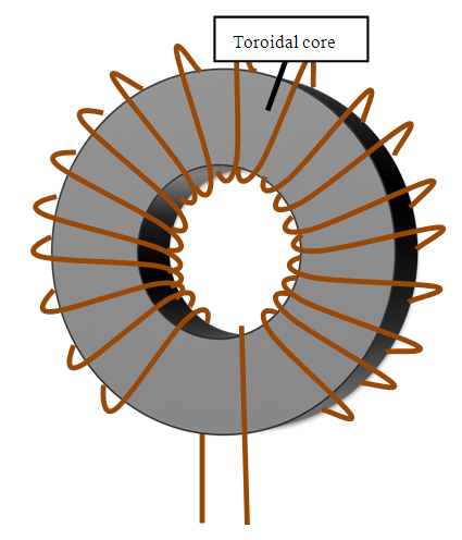 | Figure 1. Configuration of wire coil inductance method |
The two values  and A are derived using the inner radius r1 of the toroidal core, outer radius r2, thickness h, and constants C1 and C2, as follows;
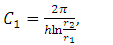 | (3) |
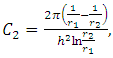 | (4) |
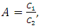 | (5) |
 | (6) |
2.2. Shunt Coaxial Line Impedance Method [10, 11]
This method loads the ferrite toroidal core to a shunt coaxial cable, and measures the impedance. By describing the impedance with the toroidal core as Zm, and that without the toroidal core as Zsm, the relative permeability  is given as follows;
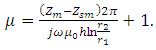 | (7) |
The problems of this method are the high cost of the measuring instrument and the size limits imposed on the toroidal core to allow coaxial cable loading.
3. Problem of Conventional Measurement Method of Ferrite Sheet
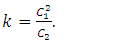
If wireless power transfer is based on electromagnetic induction, electric conductors near the transmitter and the receiver coils decrease the electric coupling coefficient, which degrades the power transfer efficiency. To avoid this influence, the conductors are covered by ferrite sheets. Ferrite sheets are also used to shield mobile phones. Such ferrite sheets are usually covered by polyethylene tape (PET) to prevent them from rupturing; a cross-section view is shown in Figure 2. To apply the conventional measurement method described in Section 2, several ferrite sheets must be processed to yield the toroidal core needed. The process consists of cutting the ferrite sheets into multiple toroids, and pasting the toroids together, as shown in Figure 3. Unfortunately, problems arise when trying to cut and stack a large number of toroids with the same size and shape. In addition, the toroidal core produced as above includes many PET layers, which influences the measured permeability values. Determining the precise permeability of the ferrite sheet requires modification of the measured results.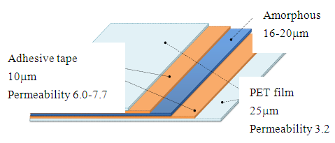 | Figure 2. Cross-section of ferrite sheet |
 | Figure 3. Fabrication of toroidal core from a ferrite sheet (cut the sheet in the form of toroids, stack and paste them) |
4. Proposed Method of Permeability Measurement
The objectives of the proposed method are;(1) simple measurement of single thin magnetic sheets,(2) determination of the real part and the imaginary part of the relative permeability, and(3) high accuracy.This paper uses the phenomenon that the inductance of a coil is raised by the permeability of the magnetic sheet. As shown in Figure 4, reactance C is measured when the coil is placed on the ferrite sheet under test on a metallic ground. This study uses two types of coils; a square spiral and a square solenoidal coil, which will be described in detail later. As the second step, reactance  is calculated by electro-magnetic simulations that assume the same configuration with hypothetical permeability
  is varied and the calculation is repeated until
  agrees with
  , as shown in the flowchart of Figure 5. The method assumes the use of a highly accurate electro-magnetic simulator.
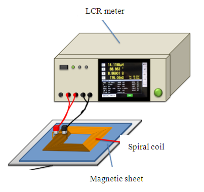 | Figure 4. Setup of measuring system using spiral coil |
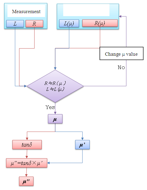 | Figure 5. Flow chart of ferrite permeability evaluation |
The square spiral coil consists of 19 turns of 0.8mm (OD) copper wire; inner side dimension is 50mm and outer side dimension is 74mm, see Figure 6. A pair of ports is placed in the middle of one side of the coil. In the experiment, an aluminum plate is used as the ground; its conductivity is assumed to be 3.8×10⁷S/m. To increase the magnetic field near the magnetic sheet and measure its permeability precisely, wrapping a solenoidal coil around the sheet is another approach, as shown in Figures 7(a) and 7(b). As the flexibility of the magnetic sheet makes it difficult to stabilize the setup of the solenoidal coil around the sheet, the sheet is sandwiched between two phenol circuit boards carrying the parallel copper wires that form the solenoidal coil. The size of the coil is 55mm x 47.5mm x 4.2mm and uses 20 turns of 2.5mm (OD) copper wire. The electro-magnetic simulator FEKO [13] is used as it offers multiple numerical methods to solve Maxwell’s equations in a wide range of electro-magnetic problems encountered in various applications.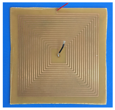 | Figure 6. Square spiral coil |
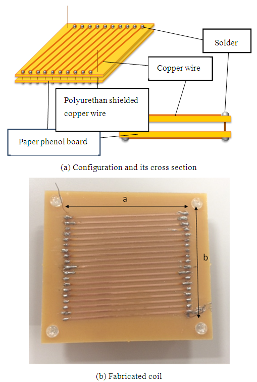 | Figure 7. Solenoidal coil |
5. Measuring the Permeability of Ferrite Sheets
The ferrite sheets used in the experiment are amorphous magnetic sheets manufactured by Toshiba Materials (SS and DS series). They consist of amorphous, adhesive and polyethylene layers, and are 30 to 100mm long, 40mm wide, and  thick, as shown in Figure 8 [14]. The manufacturer has published the relative permeability of SS and DS series from 10kHz to 200kHz, as shown in Figures 9 to 11. The SS series magnetic sheet offers high relative permeability; 60,000 at 10kHz. On the other hand, the DS series offers low permeability and low loss characteristics; the real part of its relative permeability is 2000 from 10kHz to 200kHz. This paper addresses two aspects of permeability measurement; the comparison of the two coil types in terms of accuracy, and a determination of the effect of sheet thickness.
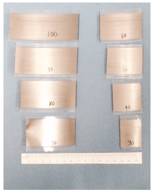 | Figure 8. Ferrite sheets |
Section 4 detailed the configuration of the spiral and the solenoidal coils used to impose a magnetic field on the ferrite sheet. By comparing the inductance measured in the experiment with that from the electro-magnetic simulator, the permeability of the ferrite sheet can be derived, as discussed in Section 4. This paper discusses the accuracy of the above measurement by comparing the derived values of the spiral and the solenoidal coils with the data provided by the manufacturer. The ferrite sheets examined had thickness of 

6. Measurement Results and Discussion
This section shows the measurement results of the permeability using the spiral and the solenoidal coils, and discusses the accuracy of the proposed methods. It also shows dependence of the permeability measurement on ferrite sheet thickness and length.
6.1. Accuracy of the Measurement Using the Spiral and the Solenoidal Coils
The measurement results of the real part of the permeability of the ferrite sheet are shown in Figure 9 for the SS series sheet with  thickness. The figure plots the results yielded by the solenoidal coil as circular markers, and those by the spiral coil as square markers. The data published by the manufacturer are shown by the dashed line and the triangular marker. The results show that the solenoidal coil results were closer to manufacturer’s data than the spiral coil results. The spiral coil results were smaller than the manufacturer’s data. However, the solenoidal coil permeability results exhibited almost the same frequency dependence as the manufacturer’s data, where the maximum error is 18%. These results indicate the possibility of accurate measurements. The measurements described in the next section were carried out using the solenoidal coil method.
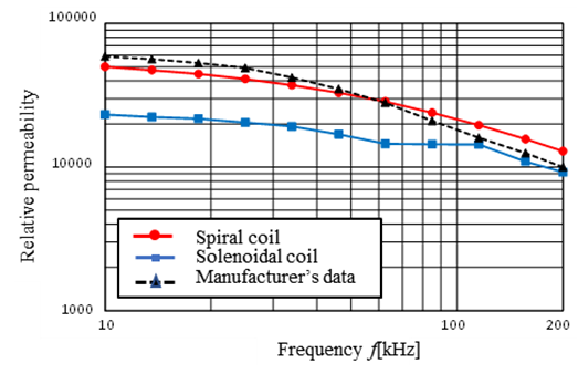 | Figure 9. Real part of the permeability measured by spiral and solenoidal coil |
6.2. Dependence of Permeability on Ferrite Sheet Thickness
The relative permeability results of SS series samples with three thicknesses are shown in Figure 10(a) with the data provided by the manufacturer as a reference; those of the DS series are shown in Figure 10(b). In both figures, regarding the real part of the relative permeability, the measurement results show almost identical frequency dependence to the manufacturer’s data. Figure 10(a) shows the real part of SS series relative permeability decreases as frequency rises, while that of the DS series is almost constant as shown in Figure 10(b). In Figure 10(a), the imaginary part reaches a maximum value at around 50kHz, which common to the experimental and the manufacturer’s data. The difference between them is large in the 10 to 30kHz range, and small in the remaining frequency ranges. Regarding the evaluated ferrite sheet thickness of  the difference is small at
  and large at
  The maximum error of the real part is 38%, and that of the imaginary part is 87%. These results show that the ferrite sheet thickness influences the difference between the experimental and the manufacturer’s data. In Figure 10(b), the experimental values of the real part of DS series samples basically agrees with the manufacturer’s data. The maximum error of the real part is 9% in the DS series samples. Note that the manufacturer has published imaginary part data only for 200 kHz.
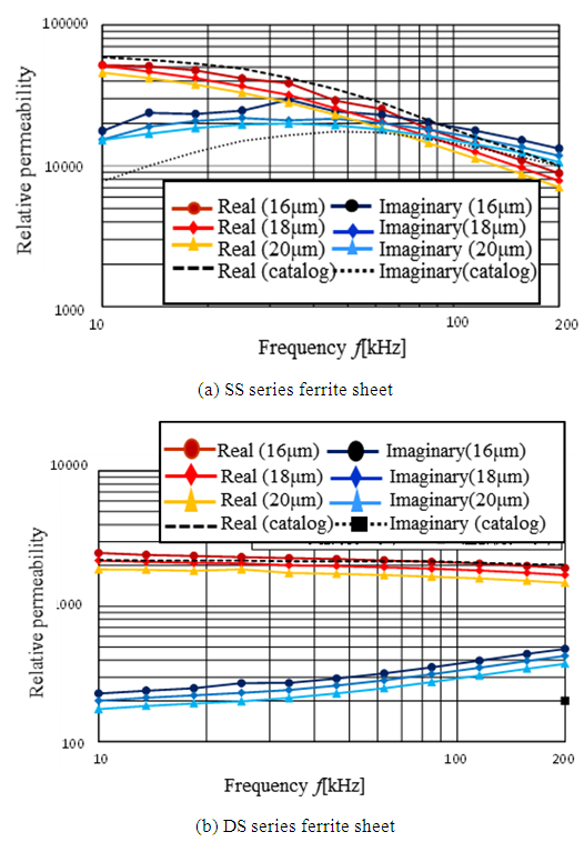 | Figure 10. Thickness dependence of the permeability |
Regarding both SS and DS series, the frequency dependence of the relative permeability is almost the same in both experimental values and the manufacturer’s data. The experimental values agree with the manufacturer’s data except for the DS series imaginary part at 200 kHz.
6.3. Dependence of Permeability on Ferrite Sheet Length
To reveal the most accurate measurement setup, this section discusses the impact of ferrite sheet length dependence on measurement preciseness. The SS series ferrite sheet samples were all 40mm wide, and the lengths examined, 30mm~100mm, in 10mm steps The measurement results of the real part of the relative permeability and that of the imaginary part are shown in Figure 11(a) and 11(b), respectively. The real part increases with sheet length, as shown in Figure 11(a). The same characteristics can be seen in the imaginary part results, except for the 30mm long sheet. The 30mm and 40mm long ferrite sheets exhibit different frequency dependence characteristics from the remaining 50mm to 100mm long sheets. Comparing the error between the measurement results and the manufacturer’s data, the error is smallest with the 100mm long sheet. The maximum error of several hundred percent occurs with 30mm long sheet in 10kHz.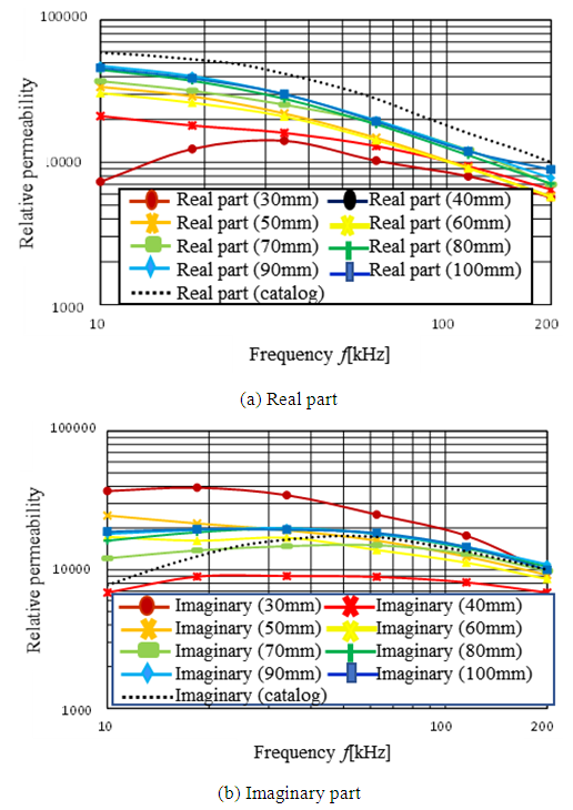 | Figure 11. Length dependence of the permeability |
7. Conclusions
To measure permeability accurately and efficiently, this paper proposes to put metallic coil in the neighborhood of the magnetic blocking sheet, evaluate the coil’s inductance and the resistance under the influence of the magnetic blocking sheet. It also proposes the use of an electromagnetic field simulator to evaluate the inductance and resistance values (for the same coil configuration) while varying the parameter of relative permeability. From the results, the permeability is determined to be the value that yields the best match between the inductance and resistance for the measured and simulated values. This paper evaluated the proposed method and showed that the solenoidal coil test method yielded almost the same frequency dependence of the permeability to the manufacturer’s data, which confirms that the offers accurate measurements. Regarding ferrite sheet thickness dependence of permeability, the difference between the experimental and the manufacturer’s data was small at  thickness, but large at
  For both SS and DS series samples, the frequency dependence characteristics of the relative permeability were almost same for the experimental values and the manufacturer’s data at all thickness. This paper also assessed the ferrite sheet length that yielded the most accurate measurements. An experiment showed the 100mm long sheet yielded the smallest error between the experimental and the manufacturer’s data for sample thicknesses in the range of 30mm to 100mm. The proposed solenoidal coil method yielded measured values that well agreed with the actual values.
ACKNOWLEDGEMENTS
This work was supported by the Nanzan University Pache Research subsidy I-A-1 and I-A-2 for the 2018 academic year.
References
| [1] | K. Fujii, M. Takahashi, and K. Ito, “Electric field distributions of wearable devices using the human body as a transmission channel,” IEEE Trans. Antennas and Propagation, vol. 55, no. 7, pp. 2080-2087, 2007. |
| [2] | A. Kurs, A. Karalis, R. Moffatt, J. D. Joannopoulos, P. Fisher, and M. Soljacic, “Wireless power transfer via strongly coupled magnetic resonances,” Science, vol.317, no.5834, pp.83-86, 2007. |
| [3] | A. Karalis, J. D. Joannopoulos, and M. Soljacic, “Efficient wireless non-radiative mid-range energy transfer,” Annals of Physics, 323, pp.34-48, 2008. |
| [4] | T. Ishizaki, T. Komori, T. Ishida, and I. Awai, “Comparative study of coil resonators for wireless power transfer system in terms of transfer loss,” IEICE Electronics Express, vol.7, no.11, pp.785-790, 2010. |
| [5] | K. Uesaka and M. Takahashi, “Antennas for Contact-Less IC Card/RFID Tag Systems,” IEICE Trans. Communications, vol. J89-B, no. 9, pp. 1548-1557, 2006. |
| [6] | N. Inagaki, “Theory of image impedance matching for inductively coupled power transfer systems,” IEEE Trans. MTT, Vol. 62, No. 4, pp.901-908, April 2014. |
| [7] | N. Inagaki, S. Hori, “Fundamentals of wireless connections with near field coupled antennas,” IEICE Trans. Communications, vol. J94-B, no. 3, pp. 436-443, 2011. |
| [8] | N. Inagaki, S. Hori, “Characterization of wireless connection systems of resonant method based on even and odd mode reactance functions and the image impedance,” IEICE Trans. Communications, vol. J94-B, no. 9, pp. 1076-1085, 2011. |
| [9] | Baker-James, et. al., “Measuring the permittivity and permeability of lossy materials: solids, liquids, metals, building materials, and negative-index materials,” NIST Technical Note, 1536, Feb. 2005. [Online] Available: https://archive.org/details/measuringpermitt1536bake. |
| [10] | Keysight Technologies, “Solutions for measuring permittivity and permeability with LCR meters and impedance analyzers,” Application Note, June 2016. |
| [11] | V. Radonic, N. Bla, and Lj Ivanov, “Measurement of complex permeability using short coaxial line Reflection method,” ACTA PHYSICA POLONICA A, Vol. 117, No. 5, 2010. |
| [12] | The International Magnetics Association Publication, “Soft Ferrites, A User’s Guide,” [Online] Available: http://www.intl-magnetics.org/publications.php. |
| [13] | Altair, “FEKO Overview,” [Online] Available: http://www.feko.info/. |
| [14] | Toshiba Materials, “Magnetic shielding sheet parts,” [Online] Available: https://www.toshiba-tmat.co.jp/en/res/theme4.htm. |

 Abstract
 Reference
 Full-Text PDF
 Full-text HTML